Manual
Page 1
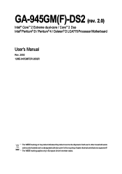
GA-945GM(F)-DS2 (rev. 2.0) Intel® CoreTM 2 Extreme dual-core / CoreTM 2 Duo Intel® Pentium® D / Pentium® 4 / Celeron® D LGA775 Processor Motherboard User's Manual Rev. 2002 12ME-945GMFDR-2002R * The WEEE marking on the product indicates this product must not be disposed of with user's other household waste and must be handed over to a designated collection point for the recycling of waste electrical and electronic equipment!! * The WEEE marking applies only in European Union's member states.
GA-945GM(F)-DS2 (rev. 2.0) Intel® CoreTM 2 Extreme dual-core / CoreTM 2 Duo Intel® Pentium® D / Pentium® 4 / Celeron® D LGA775 Processor Motherboard User's Manual Rev. 2002 12ME-945GMFDR-2002R * The WEEE marking on the product indicates this product must not be disposed of with user's other household waste and must be handed over to a designated collection point for the recycling of waste electrical and electronic equipment!! * The WEEE marking applies only in European Union's member states.

Manual
Page 2
Motherboard GA-945GM-DS2/GA-945GMF-DS2 (rev. 2.0) Nov. 10, 2006 Motherboard GA-945GM-DS2/ GA-945GMF-DS2 (rev. 2.0) Nov. 10, 2006
Motherboard GA-945GM-DS2/GA-945GMF-DS2 (rev. 2.0) Nov. 10, 2006 Motherboard GA-945GM-DS2/ GA-945GMF-DS2 (rev. 2.0) Nov. 10, 2006

Manual
Page 4
Table of Contents ItemChecklist ...6 OptionalAccessories ...6 GA-945GM(F)-DS2 (rev. 2.0) Motherboard Layout 7 Block Diagram ...8 Chapter 1 Hardware Installation 9 1-1 Considerations Prior to Installation 9 1-2 Feature Summary 10 1-3 Installation of ... 1-5 Installation of Expansion Cards 16 1-6 I/O Back Panel Introduction 17 1-7 Connectors Introduction 18 Chapter 2 BIOS Setup 29 The Main Menu (For example: GA-945GMF-DS2 BIOS Ver. : F1a 30 2-1 Standard CMOS Features 32 2-2 Advanced BIOS Features 34 2-3 IntegratedPeripherals 36 2-4 Power Management Setup 40 2-5 PnP/PCI Configurations...
Table of Contents ItemChecklist ...6 OptionalAccessories ...6 GA-945GM(F)-DS2 (rev. 2.0) Motherboard Layout 7 Block Diagram ...8 Chapter 1 Hardware Installation 9 1-1 Considerations Prior to Installation 9 1-2 Feature Summary 10 1-3 Installation of ... 1-5 Installation of Expansion Cards 16 1-6 I/O Back Panel Introduction 17 1-7 Connectors Introduction 18 Chapter 2 BIOS Setup 29 The Main Menu (For example: GA-945GMF-DS2 BIOS Ver. : F1a 30 2-1 Standard CMOS Features 32 2-2 Advanced BIOS Features 34 2-3 IntegratedPeripherals 36 2-4 Power Management Setup 40 2-5 PnP/PCI Configurations...
Manual
Page 6
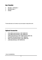
...; SPDIF In and Out Cable (Part Number: 12CR1-1SPINO-11/R) Š e-SATA Cable (Part Number: 12CF1-3SATPW-11R) Only for reference only, and are for GA-945GMF-DS2. - 6 - Item Checklist IDE Cable x 1, FDD Cable x 1 SATA 3Gb/s Cable x 1 I/O Shield * The items listed above are subject to change without notice...
...; SPDIF In and Out Cable (Part Number: 12CR1-1SPINO-11/R) Š e-SATA Cable (Part Number: 12CF1-3SATPW-11R) Only for reference only, and are for GA-945GMF-DS2. - 6 - Item Checklist IDE Cable x 1, FDD Cable x 1 SATA 3Gb/s Cable x 1 I/O Shield * The items listed above are subject to change without notice...

Manual
Page 7
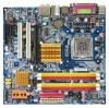
GA-945GM(F)-DS2 (rev. 2.0) Motherboard Layout KB_MS ATX_12V LGA775 CPU_FAN GA-945GM-DS2/GA-945GMF-DS2 IT8718 VGA COMA LPT USB 1394 USB LAN F_AUDIO BATTERY CLR_CMOS AUDIO SYS_FAN PCIE_16 RTL8111B PCI1 PCI2 CD_IN PCIE_1 CODEC SPDIF_IO FDD Intel® 945G DDRII1 DDRII2 BIOS TSB43AB23 Intel® ICH7 COMB F1_1394 F2_1394 DDRII3 DDRII4 SATAII0 SATAII2 IDE ATX CI F_PANEL SATAII1 SATAII3 REV: 2.0 F_USB1 F_USB2 PWR_LED Only for GA-945GMF-DS2. - 7 -
GA-945GM(F)-DS2 (rev. 2.0) Motherboard Layout KB_MS ATX_12V LGA775 CPU_FAN GA-945GM-DS2/GA-945GMF-DS2 IT8718 VGA COMA LPT USB 1394 USB LAN F_AUDIO BATTERY CLR_CMOS AUDIO SYS_FAN PCIE_16 RTL8111B PCI1 PCI2 CD_IN PCIE_1 CODEC SPDIF_IO FDD Intel® 945G DDRII1 DDRII2 BIOS TSB43AB23 Intel® ICH7 COMB F1_1394 F2_1394 DDRII3 DDRII4 SATAII0 SATAII2 IDE ATX CI F_PANEL SATAII1 SATAII3 REV: 2.0 F_USB1 F_USB2 PWR_LED Only for GA-945GMF-DS2. - 7 -
Manual
Page 8
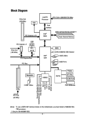
Only for GA-945GMF-DS2. - 8 - Block Diagram PCIe CLK (100 MHz) VGA PCI Express x16 PCI Express x1 PCIe CLK (100 MHz) x1 LAN RJ45 RTL 8111B x1 PCI Express ...
Only for GA-945GMF-DS2. - 8 - Block Diagram PCIe CLK (100 MHz) VGA PCI Express x16 PCI Express x1 PCIe CLK (100 MHz) x1 LAN RJ45 RTL 8111B x1 PCI Express ...

Manual
Page 10
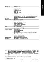
GA-945GM(F)-DS2 (rev. 2.0) Motherboard - 10 - English 1-2 Feature Summary CPU Š LGA775 for Intel® CoreTM 2 Extreme dual-core / CoreTM 2 Duo / Pentium® D / Pentium® 4 / Celeron® D Š ... 4 ports by cables Š 2 IEEE 1394a connectors for additional 2 ports by cables Š 1 COMB connector Š 1 Chassis Intrusion connector Š 1 power LED connector Only for GA-945GMF-DS2. TSB43AB23 chip Storage Š 3 IEEE 1394a ports Š Intel® ICH7 Southbrigde - 1 FDD connector, allowing connection of 1 FDD device - 1 IDE connector with CPU Front...
GA-945GM(F)-DS2 (rev. 2.0) Motherboard - 10 - English 1-2 Feature Summary CPU Š LGA775 for Intel® CoreTM 2 Extreme dual-core / CoreTM 2 Duo / Pentium® D / Pentium® 4 / Celeron® D Š ... 4 ports by cables Š 2 IEEE 1394a connectors for additional 2 ports by cables Š 1 COMB connector Š 1 Chassis Intrusion connector Š 1 power LED connector Only for GA-945GMF-DS2. TSB43AB23 chip Storage Š 3 IEEE 1394a ports Š Intel® ICH7 Southbrigde - 1 FDD connector, allowing connection of 1 FDD device - 1 IDE connector with CPU Front...
Manual
Page 11
... install a 1066/800 MHz FSB processor. (Note 3) EasyTune functions may vary depending on different motherboards. Hardware Installation For example, 4 GB of memory is reserved for GA-945GMF-DS2. - 11 - Only for system usage and therefore the actual memory size is less than the stated amount.
... install a 1066/800 MHz FSB processor. (Note 3) EasyTune functions may vary depending on different motherboards. Hardware Installation For example, 4 GB of memory is reserved for GA-945GMF-DS2. - 11 - Only for system usage and therefore the actual memory size is less than the stated amount.

Manual
Page 12
... socket. Avoid twisting or bending motions that supports HT Technology - Please set beyond the proper specifications, please do so according to the CPU during installation.) GA-945GM(F)-DS2 (rev. 2.0) Motherboard - 12 - It is properly inserted, please replace the load plate and push the metal lever back into position. (Grasping the CPU firmly between...
... socket. Avoid twisting or bending motions that supports HT Technology - Please set beyond the proper specifications, please do so according to the CPU during installation.) GA-945GM(F)-DS2 (rev. 2.0) Motherboard - 12 - It is properly inserted, please replace the load plate and push the metal lever back into position. (Grasping the CPU firmly between...
Manual
Page 14
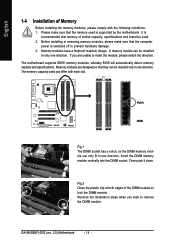
..., please switch the direction. Memory modules are unable to prevent hardware damage. 3. The memory capacity used can be used is recommended that the memory used . 2. GA-945GM(F)-DS2 (rev. 2.0) Motherboard - 14 - It is supported by the motherboard. Memory modules have a foolproof insertion design. A memory module can differ with the following conditions: 1. Fig.2 Close...
..., please switch the direction. Memory modules are unable to prevent hardware damage. 3. The memory capacity used can be used is recommended that the memory used . 2. GA-945GM(F)-DS2 (rev. 2.0) Motherboard - 14 - It is supported by the motherboard. Memory modules have a foolproof insertion design. A memory module can differ with the following conditions: 1. Fig.2 Close...

Manual
Page 15
... double. DS/SS DS/SS DDR II3 DS/SS - DS/SS DDR II2 - English Dual Channel Memory Configuration The GA-945GM-DS2/GA-945GMF-DS2 (rev. 2.0) supports the Dual Channel Technology. DS/SS DDR II4 - The GA-945GM-DS2/GA-945GMF-DS2 (rev. 2.0) includes 4 DIMM sockets, and each Channel has two DIMM sockets as following: Channel 0 : DDRII1, DDRII2 Channel 1 : DDRII3...
... double. DS/SS DS/SS DDR II3 DS/SS - DS/SS DDR II2 - English Dual Channel Memory Configuration The GA-945GM-DS2/GA-945GMF-DS2 (rev. 2.0) supports the Dual Channel Technology. DS/SS DDR II4 - The GA-945GM-DS2/GA-945GMF-DS2 (rev. 2.0) includes 4 DIMM sockets, and each Channel has two DIMM sockets as following: Channel 0 : DDRII1, DDRII2 Channel 1 : DDRII3...
Manual
Page 16
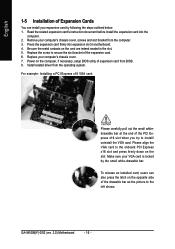
... you try to the left shows. English 1-5 Installation of Expansion Cards You can also press the latch on the card are indeed seated in motherboard. 4. GA-945GM(F)-DS2 (rev. 2.0) Motherboard - 16 - Replace your computer's chassis cover, screws and slot bracket from the operating system. Be sure the metal contacts on the opposite side...
... you try to the left shows. English 1-5 Installation of Expansion Cards You can also press the latch on the card are indeed seated in motherboard. 4. GA-945GM(F)-DS2 (rev. 2.0) Motherboard - 16 - Replace your computer's chassis cover, screws and slot bracket from the operating system. Be sure the metal contacts on the opposite side...
Manual
Page 17
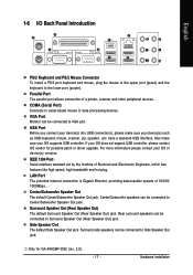
... USB Port Before you connect your device(s) into USB connector(s), please make sure your OS does not support USB controller, please contact OS vendor for GA-945GMF-DS2 (rev. 2.0). - 17 - IEEE 1394 Port Serial interface standard set by the Institute of Electrical and Electronics Engineers, which has features like high speed, high...
... USB Port Before you connect your device(s) into USB connector(s), please make sure your OS does not support USB controller, please contact OS vendor for GA-945GMF-DS2 (rev. 2.0). - 17 - IEEE 1394 Port Serial interface standard set by the Institute of Electrical and Electronics Engineers, which has features like high speed, high...

Manual
Page 18
MIC In The default MIC In jack. GA-945GM(F)-DS2 (rev. 2.0) Motherboard 10) F_PANEL 11) F_AUDIO 12) CD_IN 13) SPDIF_IO 14) F_USB1 / F_USB2 15) F1_1394 / F2_1394 16) COMB 17) CLR_CMOS 18) CI - 18 - Line Out (... information. 1-7 Connectors Introduction 1 3 17 6 9 2 11 4 7 12 18 13 5 16 15 14 8 10 1) ATX_12V 2) ATX (Power Connector) 3) CPU_FAN 4) SYS_FAN 5) FDD 6) IDE 7) SATAII0 / 1 / 2 / 3 8) PWR_LED 9) BATTERY Only for GA-945GMF-DS2. Microphone must be connected to the 2-/4-/6-/8- Please refer to MIC In jack.
MIC In The default MIC In jack. GA-945GM(F)-DS2 (rev. 2.0) Motherboard 10) F_PANEL 11) F_AUDIO 12) CD_IN 13) SPDIF_IO 14) F_USB1 / F_USB2 15) F1_1394 / F2_1394 16) COMB 17) CLR_CMOS 18) CI - 18 - Line Out (... information. 1-7 Connectors Introduction 1 3 17 6 9 2 11 4 7 12 18 13 5 16 15 14 8 10 1) ATX_12V 2) ATX (Power Connector) 3) CPU_FAN 4) SYS_FAN 5) FDD 6) IDE 7) SATAII0 / 1 / 2 / 3 8) PWR_LED 9) BATTERY Only for GA-945GMF-DS2. Microphone must be connected to the 2-/4-/6-/8- Please refer to MIC In jack.
Manual
Page 20
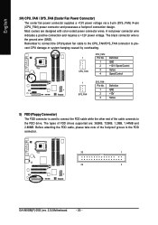
... the ground wire (GND). Most coolers are : 360KB, 720KB, 1.2MB, 1.44MB and 2.88MB. The types of the foolproof groove in the FDD connector. 33 1 34 2 GA-945GM(F)-DS2 (rev. 2.0) Motherboard - 20 - A red power connector wire indicates a positive connection and requires a +12V power voltage. English 3/4) CPU_FAN / SYS_FAN (Cooler Fan Power Connector) The cooler fan...
... the ground wire (GND). Most coolers are : 360KB, 720KB, 1.2MB, 1.44MB and 2.88MB. The types of the foolproof groove in the FDD connector. 33 1 34 2 GA-945GM(F)-DS2 (rev. 2.0) Motherboard - 20 - A red power connector wire indicates a positive connection and requires a +12V power voltage. English 3/4) CPU_FAN / SYS_FAN (Cooler Fan Power Connector) The cooler fan...
Manual
Page 22
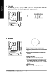
GA-945GM(F)-DS2 (rev. 2.0) Motherboard - 22 - English 8) PWR_LED The PWR_LED connector is connected with the same or equivalent type recommended by the manufacturer. Definition 1 MPD+ 2 MPD- 1 3 MPD- 9) BATTERY ...
GA-945GM(F)-DS2 (rev. 2.0) Motherboard - 22 - English 8) PWR_LED The PWR_LED connector is connected with the same or equivalent type recommended by the manufacturer. Definition 1 MPD+ 2 MPD- 1 3 MPD- 9) BATTERY ...
Manual
Page 24
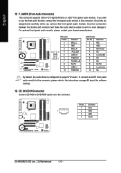
... audio function, connect the front panel audio module to the connector. Pin No. HD Audio: AC'97 Audio: Pin No. Definition 1 CD-L 1 2 GND 3 GND 4 CD-R GA-945GM(F)-DS2 (rev. 2.0) Motherboard - 24 - If you connect the front panel audio module.
... audio function, connect the front panel audio module to the connector. Pin No. HD Audio: AC'97 Audio: Pin No. Definition 1 CD-L 1 2 GND 3 GND 4 CD-R GA-945GM(F)-DS2 (rev. 2.0) Motherboard - 24 - If you connect the front panel audio module.
Manual
Page 26
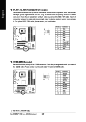
...1 10 2 Pin No. 1 2 3 4 5 6 7 8 9 10 Definition NDCDBNSINB NSOUTB NDTRBGND NDSRBNRTSBNCTSBNRIBNo Pin Only for GA-945GMF-DS2. Check the pin assignments while you connect the IEEE 1394 cable, incorrect connection between the cable and connector will make the device unable...to work or even damage it. English 15) F1_1394 / F2_1394 (Front IEEE 1394a Connector) Serial interface standard set by Institute of the COMB connector. GA-945GM(F)-DS2 (rev. 2.0) Motherboard - 26 - Check the pin assignment carefully while you connect the COMB cable. Please contact your local dealer. 9 1 10 ...
...1 10 2 Pin No. 1 2 3 4 5 6 7 8 9 10 Definition NDCDBNSINB NSOUTB NDTRBGND NDSRBNRTSBNCTSBNRIBNo Pin Only for GA-945GMF-DS2. Check the pin assignments while you connect the IEEE 1394 cable, incorrect connection between the cable and connector will make the device unable...to work or even damage it. English 15) F1_1394 / F2_1394 (Front IEEE 1394a Connector) Serial interface standard set by Institute of the COMB connector. GA-945GM(F)-DS2 (rev. 2.0) Motherboard - 26 - Check the pin assignment carefully while you connect the COMB cable. Please contact your local dealer. 9 1 10 ...

Manual
Page 28
English GA-945GM(F)-DS2 (rev. 2.0) Motherboard - 28 -
English GA-945GM(F)-DS2 (rev. 2.0) Motherboard - 28 -

Manual
Page 30
... Supervisor Password Set User Password Save & Exit Setup Exit Without Saving KLJI: Select Item F10: Save & Exit Setup Time, Date, Hard Disk Type... 1. GA-945GM(F)-DS2 (rev. 2.0) Motherboard - 30 - The BIOS Setup menus described in the BIOS Setup when somehow the system is not stable as figure below) will appear ... LS120 Hard Disk CDROM ZIP USB-FDD USB-ZIP USB-CDROM USB-HDD LAN KL:Move Enter :Accept ESC:Exit The Main Menu (For example: GA-945GMF-DS2 BIOS Ver. : F1a) Once you want, press "Ctrl+F1" to accept . Award Modular BIOS v6.00PG, An Energy Star Ally Copyright (C) 1984...
... Supervisor Password Set User Password Save & Exit Setup Exit Without Saving KLJI: Select Item F10: Save & Exit Setup Time, Date, Hard Disk Type... 1. GA-945GM(F)-DS2 (rev. 2.0) Motherboard - 30 - The BIOS Setup menus described in the BIOS Setup when somehow the system is not stable as figure below) will appear ... LS120 Hard Disk CDROM ZIP USB-FDD USB-ZIP USB-CDROM USB-HDD LAN KL:Move Enter :Accept ESC:Exit The Main Menu (For example: GA-945GMF-DS2 BIOS Ver. : F1a) Once you want, press "Ctrl+F1" to accept . Award Modular BIOS v6.00PG, An Energy Star Ally Copyright (C) 1984...


