
Manual
Page 4
Table of Contents ItemChecklist ...6 OptionalAccessories ...6 GA-945GM(F)-DS2 (rev. 2.0) Motherboard Layout 7 Block Diagram ...8 Chapter 1 Hardware Installation 9 1-1 Considerations Prior to Installation 9 1-2 Feature Summary 10 1-3 ... Installation of Expansion Cards 16 1-6 I/O Back Panel Introduction 17 1-7 Connectors Introduction 18 Chapter 2 BIOS Setup 29 The Main Menu (For example: GA-945GMF-DS2 BIOS Ver. : F1a 30 2-1 Standard CMOS Features 32 2-2 Advanced BIOS Features 34 2-3 IntegratedPeripherals 36 2-4 Power Management Setup 40 2-5 PnP/PCI Configurations 42 2-6 PC...
Table of Contents ItemChecklist ...6 OptionalAccessories ...6 GA-945GM(F)-DS2 (rev. 2.0) Motherboard Layout 7 Block Diagram ...8 Chapter 1 Hardware Installation 9 1-1 Considerations Prior to Installation 9 1-2 Feature Summary 10 1-3 ... Installation of Expansion Cards 16 1-6 I/O Back Panel Introduction 17 1-7 Connectors Introduction 18 Chapter 2 BIOS Setup 29 The Main Menu (For example: GA-945GMF-DS2 BIOS Ver. : F1a 30 2-1 Standard CMOS Features 32 2-2 Advanced BIOS Features 34 2-3 IntegratedPeripherals 36 2-4 Power Management Setup 40 2-5 PnP/PCI Configurations 42 2-6 PC...
Manual
Page 5
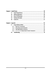
Channel Audio Function Introduction 65 4-2 Troubleshooting 70 - 5 - Chapter 3 Install Drivers 49 3-1 Install Chipset Drivers 49 3-2 SoftwareApplications 50 3-3 Driver CD Information 50 3-4 Hardware Information 51 3-5 Contact Us ...51 Chapter 4 Appendix 53 4-1 Unique Software Utilities 53 4-1-1 EasyTune 5 Introduction 53 4-1-2 Xpress Recovery2 Introduction 54 4-1-3 Flash BIOS Method Introduction 56 4-1-4 2- / 4- / 6- / 8-
Channel Audio Function Introduction 65 4-2 Troubleshooting 70 - 5 - Chapter 3 Install Drivers 49 3-1 Install Chipset Drivers 49 3-2 SoftwareApplications 50 3-3 Driver CD Information 50 3-4 Hardware Information 51 3-5 Contact Us ...51 Chapter 4 Appendix 53 4-1 Unique Software Utilities 53 4-1-1 EasyTune 5 Introduction 53 4-1-2 Xpress Recovery2 Introduction 54 4-1-3 Flash BIOS Method Introduction 56 4-1-4 2- / 4- / 6- / 8-

Manual
Page 7
GA-945GM(F)-DS2 (rev. 2.0) Motherboard Layout KB_MS ATX_12V LGA775 CPU_FAN GA-945GM-DS2/GA-945GMF-DS2 IT8718 VGA COMA LPT USB 1394 USB LAN F_AUDIO BATTERY CLR_CMOS AUDIO SYS_FAN PCIE_16 RTL8111B PCI1 PCI2 CD_IN PCIE_1 CODEC SPDIF_IO FDD Intel® 945G DDRII1 DDRII2 BIOS TSB43AB23 Intel® ICH7 COMB F1_1394 F2_1394 DDRII3 DDRII4 SATAII0 SATAII2 IDE ATX CI F_PANEL SATAII1 SATAII3 REV: 2.0 F_USB1 F_USB2 PWR_LED Only for GA-945GMF-DS2. - 7 -
GA-945GM(F)-DS2 (rev. 2.0) Motherboard Layout KB_MS ATX_12V LGA775 CPU_FAN GA-945GM-DS2/GA-945GMF-DS2 IT8718 VGA COMA LPT USB 1394 USB LAN F_AUDIO BATTERY CLR_CMOS AUDIO SYS_FAN PCIE_16 RTL8111B PCI1 PCI2 CD_IN PCIE_1 CODEC SPDIF_IO FDD Intel® 945G DDRII1 DDRII2 BIOS TSB43AB23 Intel® ICH7 COMB F1_1394 F2_1394 DDRII3 DDRII4 SATAII0 SATAII2 IDE ATX CI F_PANEL SATAII1 SATAII3 REV: 2.0 F_USB1 F_USB2 PWR_LED Only for GA-945GMF-DS2. - 7 -
Manual
Page 8
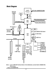
Only for GA-945GMF-DS2. - 8 - Block Diagram PCIe CLK (100 MHz) VGA PCI Express x16 PCI Express x1 PCIe CLK (100 MHz) x1 LAN RJ45 RTL 8111B x1 PCI Express ... Processor CPU CLK+/-(266/200/133 MHz) Host Interface Intel® 945G DDRII 667/533/400 MHz DIMM(Note) Dual Channel Memory Intel® ICH7 BIOS ATA 33/66/100 IDE Channel 4 SATA 3Gb/s 8 USB Ports TSB43AB23 2 PCI 3 IEEE 1394a PCI CLK (33 MHz) CODEC IT8718 Floppy LPT Port COM Ports...
Only for GA-945GMF-DS2. - 8 - Block Diagram PCIe CLK (100 MHz) VGA PCI Express x16 PCI Express x1 PCIe CLK (100 MHz) x1 LAN RJ45 RTL 8111B x1 PCI Express ... Processor CPU CLK+/-(266/200/133 MHz) Host Interface Intel® 945G DDRII 667/533/400 MHz DIMM(Note) Dual Channel Memory Intel® ICH7 BIOS ATA 33/66/100 IDE Channel 4 SATA 3Gb/s 8 USB Ports TSB43AB23 2 PCI 3 IEEE 1394a PCI CLK (33 MHz) CODEC IT8718 Floppy LPT Port COM Ports...
Manual
Page 11
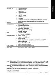
For example, 4 GB of memory is reserved for GA-945GMF-DS2. - 11 - English Rear Panel I/O Š 1 PS/2 keyboard port Š 1 PS/2 mouse port Š 1 parallel port Š 1 serial port (COMA) Š 1 VGA port Š 4 USB 2.0/1.1... Š Supports Q-Flash Š Supports EasyTune (only supports Hardware Monitor function)(Note 3) Š Supports Xpress Install Š Supports Xpress Recovery2 Š Supports Xpress BIOS Rescue Bundle Software Š Norton Internet Security (OEM revision) Form Factor Š Micro ATX form factor; 24.4cm x 23.3cm (Note 1) Due to standard ...
For example, 4 GB of memory is reserved for GA-945GMF-DS2. - 11 - English Rear Panel I/O Š 1 PS/2 keyboard port Š 1 PS/2 mouse port Š 1 parallel port Š 1 serial port (COMA) Š 1 VGA port Š 4 USB 2.0/1.1... Š Supports Q-Flash Š Supports EasyTune (only supports Hardware Monitor function)(Note 3) Š Supports Xpress Install Š Supports Xpress Recovery2 Š Supports Xpress BIOS Rescue Bundle Software Š Norton Internet Security (OEM revision) Form Factor Š Micro ATX form factor; 24.4cm x 23.3cm (Note 1) Due to standard ...

Manual
Page 12
... functionality of Hyper-Threading Technology for HT Technology 1-3-1 Installation of the CPU Metal Lever Fig. 1 Gently lift the metal lever located on the CPU socket. BIOS: A BIOS that the motherboard supports the CPU. 2. Please add an even layer of the CPU. Fig. 3 Notice the small gold colored triangle located on the CPU... be set the CPU host frequency in a straight and downwards motion. Fig. 2 Remove the plastic covering on the CPU socket to the CPU during installation.) GA-945GM(F)-DS2 (rev. 2.0) Motherboard - 12 -
... functionality of Hyper-Threading Technology for HT Technology 1-3-1 Installation of the CPU Metal Lever Fig. 1 Gently lift the metal lever located on the CPU socket. BIOS: A BIOS that the motherboard supports the CPU. 2. Please add an even layer of the CPU. Fig. 3 Notice the small gold colored triangle located on the CPU... be set the CPU host frequency in a straight and downwards motion. Fig. 2 Remove the plastic covering on the CPU socket to the CPU during installation.) GA-945GM(F)-DS2 (rev. 2.0) Motherboard - 12 -
Manual
Page 14
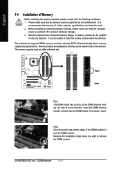
... they can differ with the following conditions: 1. The motherboard supports DDRII memory modules, whereby BIOS will automatically detect memory capacity and specifications. The memory capacity used . 2. A memory module can only fit in one direction. Then push it down. GA-945GM(F)-DS2 (rev. 2.0) Motherboard - 14 - English 1-4 Installation of Memory Before installing the memory modules, please...
... they can differ with the following conditions: 1. The motherboard supports DDRII memory modules, whereby BIOS will automatically detect memory capacity and specifications. The memory capacity used . 2. A memory module can only fit in one direction. Then push it down. GA-945GM(F)-DS2 (rev. 2.0) Motherboard - 14 - English 1-4 Installation of Memory Before installing the memory modules, please...
Manual
Page 16
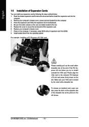
... from the computer. 3. Power on the opposite side of Expansion Cards You can also press the latch on the computer, if necessary, setup BIOS utility of the expansion card. 6. GA-945GM(F)-DS2 (rev. 2.0) Motherboard - 16 - Read the related expansion card's instruction document before install the expansion card into expansion slot in the slot. 5. Please...
... from the computer. 3. Power on the opposite side of Expansion Cards You can also press the latch on the computer, if necessary, setup BIOS utility of the expansion card. 6. GA-945GM(F)-DS2 (rev. 2.0) Motherboard - 16 - Read the related expansion card's instruction document before install the expansion card into expansion slot in the slot. 5. Please...
Manual
Page 21
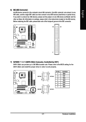
... groove in order to work properly. 1 SATAII2 7 1 SATAII0 7 SATAII3 1 7 SATAII1 Pin No. 1 2 3 4 5 6 7 Definition GND TXP TXN GND RXN RXP GND 7 1 - 21 - Please refer to the BIOS setting for information on the IDE device). English 6) IDE (IDE Connector) An IDE device connects to two IDE devices (hard drive or optical drive). If...
... groove in order to work properly. 1 SATAII2 7 1 SATAII0 7 SATAII3 1 7 SATAII1 Pin No. 1 2 3 4 5 6 7 Definition GND TXP TXN GND RXN RXP GND 7 1 - 21 - Please refer to the BIOS setting for information on the IDE device). English 6) IDE (IDE Connector) An IDE device connects to two IDE devices (hard drive or optical drive). If...

Manual
Page 27
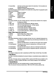
English 17) CLR_CMOS (Clear CMOS) You may clear the CMOS data to its default values by this header. Definition 1 Signal 1 2 GND - 27 - To clear CMOS, temporarily short the two pins. You can check the "Case Opened" status in BIOS Setup. Pin No. Default doesn't include the jumper to detect if the chassis cover is removed. Open: Normal Short: Clear CMOS 18) CI (Chassis Intrusion, Case Open) This 2-pin connector allows your system to avoid improper use of this header. Hardware Installation
English 17) CLR_CMOS (Clear CMOS) You may clear the CMOS data to its default values by this header. Definition 1 Signal 1 2 GND - 27 - To clear CMOS, temporarily short the two pins. You can check the "Case Opened" status in BIOS Setup. Pin No. Default doesn't include the jumper to detect if the chassis cover is removed. Open: Normal Short: Clear CMOS 18) CI (Chassis Intrusion, Case Open) This 2-pin connector allows your system to avoid improper use of this header. Hardware Installation

Manual
Page 29
... Setup Menu Load the Fail-safe default CMOS value from the Internet. If you to activate certain system features. CONTROL KEYS Enter> Move to a new BIOS, either GIGABYTE's Q-Flash or @BIOS utility can enter the BIOS setup screen by pressing "Ctrl + F1". To exit the Help Window press .
... Setup Menu Load the Fail-safe default CMOS value from the Internet. If you to activate certain system features. CONTROL KEYS Enter> Move to a new BIOS, either GIGABYTE's Q-Flash or @BIOS utility can enter the BIOS setup screen by pressing "Ctrl + F1". To exit the Help Window press .

Manual
Page 30
...Hard Disk CDROM ZIP USB-FDD USB-ZIP USB-CDROM USB-HDD LAN KL:Move Enter :Accept ESC:Exit The Main Menu (For example: GA-945GMF-DS2 BIOS Ver. : F1a) Once you want, press "Ctrl+F1" to exit this chapter are for reference only and may differ from the ... appear on cards) device. English : Boot Menu Select boot sequence for onboard (or add-on the screen. Award Modular BIOS v6.00PG, An Energy Star Ally Copyright (C) 1984-2006, Award Software, Inc. Intel I945 BIOS for stability. 3. GA-945GM(F)-DS2 (rev. 2.0) Motherboard - 30 - Select the Load Optimized Defaults item in this menu.
...Hard Disk CDROM ZIP USB-FDD USB-ZIP USB-CDROM USB-HDD LAN KL:Move Enter :Accept ESC:Exit The Main Menu (For example: GA-945GMF-DS2 BIOS Ver. : F1a) Once you want, press "Ctrl+F1" to exit this chapter are for reference only and may differ from the ... appear on cards) device. English : Boot Menu Select boot sequence for onboard (or add-on the screen. Award Modular BIOS v6.00PG, An Energy Star Ally Copyright (C) 1984-2006, Award Software, Inc. Intel I945 BIOS for stability. 3. GA-945GM(F)-DS2 (rev. 2.0) Motherboard - 30 - Select the Load Optimized Defaults item in this menu.

Manual
Page 31
...configuration. „ Load Optimized Defaults Optimized Defaults indicates the value of the system parameters which the system would be in standard compatible BIOS. „ Advanced BIOS Features This setup page includes all the items of Award special enhanced features. „ Integrated Peripherals This setup page includes all ...the items of Green function features. „ PnP/PCI Configuration This setup page includes all CMOS value changes and exit setup. - 31 - BIOS Setup It allows you to limit access to the system. „ Save & Exit Setup Save CMOS value settings to Setup. „ Set...
...configuration. „ Load Optimized Defaults Optimized Defaults indicates the value of the system parameters which the system would be in standard compatible BIOS. „ Advanced BIOS Features This setup page includes all the items of Award special enhanced features. „ Integrated Peripherals This setup page includes all ...the items of Green function features. „ PnP/PCI Configuration This setup page includes all CMOS value changes and exit setup. - 31 - BIOS Setup It allows you to limit access to the system. „ Save & Exit Setup Save CMOS value settings to Setup. „ Set...

Manual
Page 32
...Slave IDE devices setup. IDE Channel 2, 3 Master/Slave IDE HDD Auto-Detection Press "Enter" to select this option for automatic device detection. GA-945GM(F)-DS2 (rev. 2.0) Motherboard - 32 - is calculated base on the 24-hour military- IDE Channel 0 Master/Slave IDE HDD Auto-Detection Press...device detection. The four options are: CHS/LBA/Large/Auto(default:Auto) Capacity Capacity of three methods: • Auto Allows BIOS to automatically detect IDE/SATA devices during POST. (Default value) • None Select this to automatically detect IDE/SATA devices ...
...Slave IDE devices setup. IDE Channel 2, 3 Master/Slave IDE HDD Auto-Detection Press "Enter" to select this option for automatic device detection. GA-945GM(F)-DS2 (rev. 2.0) Motherboard - 32 - is calculated base on the 24-hour military- IDE Channel 0 Master/Slave IDE HDD Auto-Detection Press...device detection. The four options are: CHS/LBA/Large/Auto(default:Auto) Capacity Capacity of three methods: • Auto Allows BIOS to automatically detect IDE/SATA devices during POST. (Default value) • None Select this to automatically detect IDE/SATA devices ...
Manual
Page 33
...-type high-density drive; 1.2M byte capacity (3.5 inch when 3 Mode is the amount of the BIOS. All, But Disk/Key The system boot will stop for all other errors. BIOS Setup Hard drive information should be detected and you All Errors will stop for all other errors. Halt... base (or conventional) memory installed in the system. English Access Mode Use this information. Whenever the BIOS detects a non-fatal error the system will determine the amount of the BIOS will be prompted. Memory The category is display-only which is detected during the POST. No Errors...
...-type high-density drive; 1.2M byte capacity (3.5 inch when 3 Mode is the amount of the BIOS. All, But Disk/Key The system boot will stop for all other errors. BIOS Setup Hard drive information should be detected and you All Errors will stop for all other errors. Halt... base (or conventional) memory installed in the system. English Access Mode Use this information. Whenever the BIOS detects a non-fatal error the system will determine the amount of the BIOS will be prompted. Memory The category is display-only which is detected during the POST. No Errors...

Manual
Page 34
... your boot device priority by USB-HDD. ZIP Select your boot device priority by ZIP. LAN Select your boot device priority by LAN. GA-945GM(F)-DS2 (rev. 2.0) Motherboard - 34 - Select your boot device priority by Hard Disk. USB-CDROM Select your boot device priority by USB-CDROM...by Floppy. USB-FDD USB-ZIP Select your boot device priority by USB-FDD. English 2-2 Advanced BIOS Features CMOS Setup Utility-Copyright (C) 1984-2006 Award Software Advanced BIOS Features ` Hard Disk Boot Priority First Boot Device Second Boot Device Third Boot Device Password Check HDD...
... your boot device priority by USB-HDD. ZIP Select your boot device priority by ZIP. LAN Select your boot device priority by LAN. GA-945GM(F)-DS2 (rev. 2.0) Motherboard - 34 - Select your boot device priority by Hard Disk. USB-CDROM Select your boot device priority by USB-CDROM...by Floppy. USB-FDD USB-ZIP Select your boot device priority by USB-FDD. English 2-2 Advanced BIOS Features CMOS Setup Utility-Copyright (C) 1984-2006 Award Software Advanced BIOS Features ` Hard Disk Boot Priority First Boot Device Second Boot Device Third Boot Device Password Check HDD...

Manual
Page 35
... Monitor 2 (TM2) function. Enabled Enable HDD S.M.A.R.T. Disabled Disable CPUID Limit for operating system with multi processors mode supported. (Default value) Disabled Disable CPU Hyper Threading. BIOS Setup to 3 (Note) Enabled Limit CPUID Maximum value to 3 when use older OS like NT4. Virtualization Technology (Note) Enabled Enable Virtualization technology function. (Default value...
... Monitor 2 (TM2) function. Enabled Enable HDD S.M.A.R.T. Disabled Disable CPUID Limit for operating system with multi processors mode supported. (Default value) Disabled Disable CPU Hyper Threading. BIOS Setup to 3 (Note) Enabled Limit CPUID Maximum value to 3 when use older OS like NT4. Virtualization Technology (Note) Enabled Enable Virtualization technology function. (Default value...
Manual
Page 36
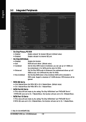
... IDE port. Auto Combined BIOS will auto make by the setting "On-Chip SATA Mode" and "PATA IDE Set to Combined, you can use ; 4 for SATA and the other for PATA. SATA Port 0/2 Set to This value will auto detect. (Default value) Set On-Chip SATA mode to ". GA-945GM(F)-DS2 (rev. 2.0) Motherboard - 36... will auto make by the setting "On-Chip SATA Mode" and "PATA IDE Set to 4 HDDs on the motherboard; 2 for SATA and the other for GA-945GMF-DS2. If PATA IDE were set to Ch. 0 Master/Slave. SATA Port 1/3 Set to This value will auto set to Ch. 0 Master/Slave, this function...
... IDE port. Auto Combined BIOS will auto make by the setting "On-Chip SATA Mode" and "PATA IDE Set to Combined, you can use ; 4 for SATA and the other for PATA. SATA Port 0/2 Set to This value will auto detect. (Default value) Set On-Chip SATA mode to ". GA-945GM(F)-DS2 (rev. 2.0) Motherboard - 36... will auto make by the setting "On-Chip SATA Mode" and "PATA IDE Set to 4 HDDs on the motherboard; 2 for SATA and the other for GA-945GMF-DS2. If PATA IDE were set to Ch. 0 Master/Slave. SATA Port 1/3 Set to This value will auto set to Ch. 0 Master/Slave, this function...
Manual
Page 37
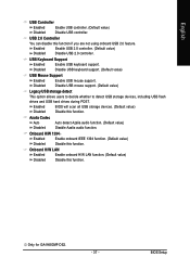
... Support Enabled Enable USB keyboard support. Azalia Codec Auto Auto detect Azalia audio function. (Default value) Disabled Disable Azalia audio function. Only for GA-945GMF-DS2. - 37 - Enabled Disabled BIOS will scan all USB storage devices. (Default value) Disable this function. Onboard H/W LAN Enabled Disabled Enable onboard H/W LAN function. (Default value) Disable this... to decide whether to detect USB storage devices, including USB flash drives and USB hard drives during POST. USB 2.0 Controller You can disable this function. BIOS Setup
... Support Enabled Enable USB keyboard support. Azalia Codec Auto Auto detect Azalia audio function. (Default value) Disabled Disable Azalia audio function. Only for GA-945GMF-DS2. - 37 - Enabled Disabled BIOS will scan all USB storage devices. (Default value) Disable this function. Onboard H/W LAN Enabled Disabled Enable onboard H/W LAN function. (Default value) Disable this... to decide whether to detect USB storage devices, including USB flash drives and USB hard drives during POST. USB 2.0 Controller You can disable this function. BIOS Setup

Manual
Page 39
...2E8/IRQ3. ECP Using LPT port as ECP & EPP mode. ECP+EPP Using LPT port as Extended Capabilities Port. Onboard Serial Port 2 Auto BIOS will automatically setup the port 1 address. 3F8/IRQ4 Enable onboard Serial port 1 and address is 3F8/IRQ4. (Default value) 2F8/IRQ3 Enable .../IRQ4. 2E8/IRQ3 Enable onboard Serial port 1 and address is 3BC/IRQ7. Enabled Enable this function. (Default value) Onboard Serial Port 1 Auto BIOS will automatically setup the port 2 address. 3F8/IRQ4 Enable onboard Serial port 2 and address is 3F8/IRQ4. 2F8/IRQ3 Enable onboard Serial port 2...
...2E8/IRQ3. ECP Using LPT port as ECP & EPP mode. ECP+EPP Using LPT port as Extended Capabilities Port. Onboard Serial Port 2 Auto BIOS will automatically setup the port 1 address. 3F8/IRQ4 Enable onboard Serial port 1 and address is 3F8/IRQ4. (Default value) 2F8/IRQ3 Enable .../IRQ4. 2E8/IRQ3 Enable onboard Serial port 1 and address is 3BC/IRQ7. Enabled Enable this function. (Default value) Onboard Serial Port 1 Auto BIOS will automatically setup the port 2 address. 3F8/IRQ4 Enable onboard Serial port 2 and address is 3F8/IRQ4. 2F8/IRQ3 Enable onboard Serial port 2...


