Manual
Page 1
GA-945GCM-S2L/ GA-945GCM-S2C LGA775 socket motherboard for Intel® CoreTM processor family/ Intel® Pentium® processor family/Intel® Celeron® processor family User's Manual Rev. 1007 12ME-945GCMS2-1007R
GA-945GCM-S2L/ GA-945GCM-S2C LGA775 socket motherboard for Intel® CoreTM processor family/ Intel® Pentium® processor family/Intel® Celeron® processor family User's Manual Rev. 1007 12ME-945GCMS2-1007R
Manual
Page 2
Motherboard GA-945GCM-S2L/GA-945GCM-S2C Aug. 27, 2007 Motherboard GA-945GCM-S2L/ GA-945GCM-S2C Aug. 27, 2007
Motherboard GA-945GCM-S2L/GA-945GCM-S2C Aug. 27, 2007 Motherboard GA-945GCM-S2L/ GA-945GCM-S2C Aug. 27, 2007
Manual
Page 3
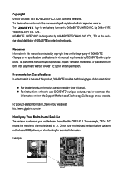
...this manual may be made by any form or by GIGABYTE without GIGABYTE's prior written permission. For product-related information, check on our website at: http://www.gigabyte.com.tw Identifying Your Motherboard Revision The revision number on how to their respective ...or download the information on/from the Support\Motherboard\Technology Guide page on our website. Check your motherboard looks like this product, GIGABYTE provides the following types of the motherboard is designated by GIGA-BYTE TECHNOLOGY CO., LTD. GIGABYTE UNITED INC. is 1.0. All rights reserved....
...this manual may be made by any form or by GIGABYTE without GIGABYTE's prior written permission. For product-related information, check on our website at: http://www.gigabyte.com.tw Identifying Your Motherboard Revision The revision number on how to their respective ...or download the information on/from the Support\Motherboard\Technology Guide page on our website. Check your motherboard looks like this product, GIGABYTE provides the following types of the motherboard is designated by GIGA-BYTE TECHNOLOGY CO., LTD. GIGABYTE UNITED INC. is 1.0. All rights reserved....
Manual
Page 4
Table of Contents Box Contents ...6 OptionalItems...6 GA-945GCM-S2L/GA-945GCM-S2C Motherboard Layout 7 Block Diagram...8 Chapter 1 Hardware Installation 9 1-1 Installation Precautions 9 1-2 Product Specifications 10 1-3 Installing the CPU and CPU Cooler 13 1-3-1 Installing the CPU 13 1-3-2 Installing the CPU ...
Table of Contents Box Contents ...6 OptionalItems...6 GA-945GCM-S2L/GA-945GCM-S2C Motherboard Layout 7 Block Diagram...8 Chapter 1 Hardware Installation 9 1-1 Installation Precautions 9 1-2 Product Specifications 10 1-3 Installing the CPU and CPU Cooler 13 1-3-1 Installing the CPU 13 1-3-2 Installing the CPU ...
Manual
Page 6
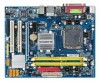
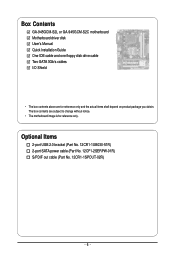
Box Contents GA-945GCM-S2L or GA-945GCM-S2C motherboard Motherboard driver disk User's Manual Quick Installation Guide One IDE cable and one floppy disk drive cable Two SATA 3Gb/s cables I/O Shield • The box contents above are subject to change without notice. • The motherboard image is for reference only and the actual items shall depend on product...
Box Contents GA-945GCM-S2L or GA-945GCM-S2C motherboard Motherboard driver disk User's Manual Quick Installation Guide One IDE cable and one floppy disk drive cable Two SATA 3Gb/s cables I/O Shield • The box contents above are subject to change without notice. • The motherboard image is for reference only and the actual items shall depend on product...
Manual
Page 7
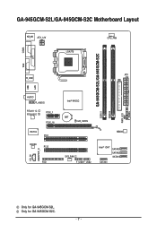
GA-945GCM-S2L/GA-945GCM-S2C Motherboard Layout KB_MS ATX_12V LGA775 CPU_FAN COMA CI GA-945GCM-S2L/GA-945GCM-S2C DDRII1 DDRII2 PWR_LED F_PANEL LPT LAN VGA R_USB ATX IDE USB AUDIO F_AUDIO RTL8111C RTL8101E PCIE_1 PCIE_16 IT8718 PCI1 CODEC PCI2 CD_IN SPDIF_O FDD Intel® 945GC BAT CLR_CMOS MBIOS SYS_FAN F_USB1F_USB2 Intel® ICH7 SATAII3 SATAII2 SATAII1 SATAII0 Only for GA-945GCM-S2C. - 7 - Only for GA-945GCM-S2L.
GA-945GCM-S2L/GA-945GCM-S2C Motherboard Layout KB_MS ATX_12V LGA775 CPU_FAN COMA CI GA-945GCM-S2L/GA-945GCM-S2C DDRII1 DDRII2 PWR_LED F_PANEL LPT LAN VGA R_USB ATX IDE USB AUDIO F_AUDIO RTL8111C RTL8101E PCIE_1 PCIE_16 IT8718 PCI1 CODEC PCI2 CD_IN SPDIF_O FDD Intel® 945GC BAT CLR_CMOS MBIOS SYS_FAN F_USB1F_USB2 Intel® ICH7 SATAII3 SATAII2 SATAII1 SATAII0 Only for GA-945GCM-S2C. - 7 - Only for GA-945GCM-S2L.
Manual
Page 9
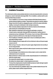
... Before using the product, please verify that all cables and power connectors of your hardware components are connected. • To prevent damage to the motherboard, do not have it on top of an antistatic pad or within the computer casing. • Do not place the computer system on an uneven... surface. • Do not place the computer system in contact with the motherboard circuit or its components. • Make sure there are required for warranty validation. • Always remove the AC power by your hands dry and...
... Before using the product, please verify that all cables and power connectors of your hardware components are connected. • To prevent damage to the motherboard, do not have it on top of an antistatic pad or within the computer casing. • Do not place the computer system on an uneven... surface. • Do not place the computer system in contact with the motherboard circuit or its components. • Make sure there are required for warranty validation. • Always remove the AC power by your hands dry and...
Manual
Page 10
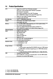
...Intel® Pentium® 4 processor/ Intel® Celeron® processor in the LGA 775 package (Go to GIGABYTE's website for the latest CPU support list.) Š Support for Intel® Hyper-Threading Technology Š L2 ...; Dual channel memory architecture Š Support for DDR2 667/533/400 MHz memory modules (Note 3) (Go to GIGABYTE's website for the latest memory support list.) Š Integrated in the North Bridge Š Realtek ALC662 codec ... brackets connected to the internal USB headers) Only for GA-945GCM-S2C. GA-945GCM-S2L/S2C Motherboard - 10 - Only for GA-945GCM-S2L.
...Intel® Pentium® 4 processor/ Intel® Celeron® processor in the LGA 775 package (Go to GIGABYTE's website for the latest CPU support list.) Š Support for Intel® Hyper-Threading Technology Š L2 ...; Dual channel memory architecture Š Support for DDR2 667/533/400 MHz memory modules (Note 3) (Go to GIGABYTE's website for the latest memory support list.) Š Integrated in the North Bridge Š Realtek ALC662 codec ... brackets connected to the internal USB headers) Only for GA-945GCM-S2C. GA-945GCM-S2L/S2C Motherboard - 10 - Only for GA-945GCM-S2L.
Manual
Page 12
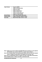
... of a 1066/800 MHz FSB CPU is required if you wish to install DDR2 667 MHz memory. (Note 4) Available functions in Easytune may differ by motherboard model. You must install the FSB 1333 MHz CoreTM 2 CPU with 1333 MHz FSB through overclocking. GA-945GCM-S2L/S2C Motherboard - 12 -
... of a 1066/800 MHz FSB CPU is required if you wish to install DDR2 667 MHz memory. (Note 4) Available functions in Easytune may differ by motherboard model. You must install the FSB 1333 MHz CoreTM 2 CPU with 1333 MHz FSB through overclocking. GA-945GCM-S2L/S2C Motherboard - 12 -
Manual
Page 13
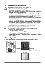
... it does not meet the standard requirements for the peripherals. It is optimized for HT Technology • A BIOS that the motherboard supports the CPU. (Go to GIGABYTE's website for the latest CPU support list.) • Always turn on enabling the HT Technology.) 1-3-1 Installing the CPU A....so according to your hardware specifications including the CPU, graphics card, memory, hard drive, etc. Locate the alignment keys on the motherboard CPU socket and the notches on the CPU Hardware Installation 1-3 Installing the CPU and CPU Cooler Read the following guidelines before installing ...
... it does not meet the standard requirements for the peripherals. It is optimized for HT Technology • A BIOS that the motherboard supports the CPU. (Go to GIGABYTE's website for the latest CPU support list.) • Always turn on enabling the HT Technology.) 1-3-1 Installing the CPU A....so according to your hardware specifications including the CPU, graphics card, memory, hard drive, etc. Locate the alignment keys on the motherboard CPU socket and the notches on the CPU Hardware Installation 1-3 Installing the CPU and CPU Cooler Read the following guidelines before installing ...
Manual
Page 14
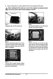
... one marking (triangle) with the pin one corner of the CPU socket (or you may align the CPU notches with your thumb and index fingers. GA-945GCM-S2L/S2C Motherboard - 14 - Step 2: Lift the metal load plate from the CPU socket. (DO NOT touch socket contacts.) Step 3: Remove the protective socket cover from the...
... one marking (triangle) with the pin one corner of the CPU socket (or you may align the CPU notches with your thumb and index fingers. GA-945GCM-S2L/S2C Motherboard - 14 - Step 2: Lift the metal load plate from the CPU socket. (DO NOT touch socket contacts.) Step 3: Remove the protective socket cover from the...
Manual
Page 15
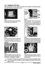
... above, the installation is to install.) Step 3: Place the cooler atop the CPU, aligning the four push pins through the pin holes on the motherboard. Step 4: You should hear a "click" when pushing down on the push pins diagonally. Check that the Male and Female push pins are joined... of the installed CPU. Inadequately removing the CPU cooler may adhere to your CPU cooler installation manual for instructions on the surface of the motherboard. Use extreme care when removing the CPU cooler because the thermal grease/tape between the CPU cooler and CPU may damage the CPU. -...
... above, the installation is to install.) Step 3: Place the cooler atop the CPU, aligning the four push pins through the pin holes on the motherboard. Step 4: You should hear a "click" when pushing down on the push pins diagonally. Check that the Male and Female push pins are joined... of the installed CPU. Inadequately removing the CPU cooler may adhere to your CPU cooler installation manual for instructions on the surface of the motherboard. Use extreme care when removing the CPU cooler because the thermal grease/tape between the CPU cooler and CPU may damage the CPU. -...
Manual
Page 16
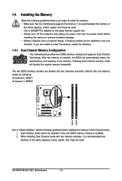
... the Memory Read the following guidelines before installing the memory in only one direction. Dual Channel mode cannot be used . (Go to GIGABYTE's website for the latest memory support list.) • Always turn off the computer and unplug the power cord from the power outlet ...channel has one DDR2 memory module is recommended that memory of the memory. It is installed, the BIOS will double the original memory bandwidth. GA-945GCM-S2L/S2C Motherboard - 16 - After the memory is recommended that memory of the same capacity, brand, speed, and chips be enabled if only one ...
... the Memory Read the following guidelines before installing the memory in only one direction. Dual Channel mode cannot be used . (Go to GIGABYTE's website for the latest memory support list.) • Always turn off the computer and unplug the power cord from the power outlet ...channel has one DDR2 memory module is recommended that memory of the memory. It is installed, the BIOS will double the original memory bandwidth. GA-945GCM-S2L/S2C Motherboard - 16 - After the memory is recommended that memory of the same capacity, brand, speed, and chips be enabled if only one ...
Manual
Page 17
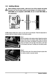
... fingers on the top edge of the memory socket. DDR2 DIMMs are not compatible to DDR DIMMs. Be sure to install DDR2 DIMMs on this motherboard.
... fingers on the top edge of the memory socket. DDR2 DIMMs are not compatible to DDR DIMMs. Be sure to install DDR2 DIMMs on this motherboard.
Manual
Page 18
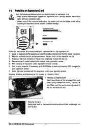
.... Align the card with a screw. 5. Turn on the slot and then lift the card straight out from the chassis back panel. 2. GA-945GCM-S2L/S2C Motherboard - 18 - Install the driver provided with your card. PCI Express x16 Slot PCI Slot PCI Express x1 Slot Follow the steps below to... install an expansion card: • Make sure the motherboard supports the expansion card. Carefully read the manual that supports your expansion card. •...
.... Align the card with a screw. 5. Turn on the slot and then lift the card straight out from the chassis back panel. 2. GA-945GCM-S2L/S2C Motherboard - 18 - Install the driver provided with your card. PCI Express x16 Slot PCI Slot PCI Express x1 Slot Follow the steps below to... install an expansion card: • Make sure the motherboard supports the expansion card. Carefully read the manual that supports your expansion card. •...
Manual
Page 19
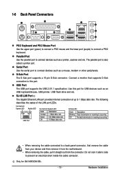
... then remove it from the motherboard. • When removing the cable, pull it side to side to connect a PS/2 keyboard. USB Port The USB port supports the USB 2.0/1.1 specification. RJ-45 LAN Port The Gigabit Ethernet LAN port provides Internet connection at up to this port for GA-945GCM-S2L. - 19 - The following...
... then remove it from the motherboard. • When removing the cable, pull it side to side to connect a PS/2 keyboard. USB Port The USB port supports the USB 2.0/1.1 specification. RJ-45 LAN Port The Gigabit Ethernet LAN port provides Internet connection at up to this port for GA-945GCM-S2L. - 19 - The following...
Manual
Page 20
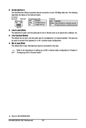
... (Pink) The default Mic in Chapter 5, "Configuring 2/4/5.1-Channel Audio." Only for a headphone or 2-channel speaker. GA-945GCM-S2L/S2C Motherboard - 20 - Use this audio jack for line in jack. Microphones must be used to this audio jack for GA-945GCM-S2C. Line Out Jack (Green) The default line out jack. Connection/ Speed LED Activity LED Connection/Speed...
... (Pink) The default Mic in Chapter 5, "Configuring 2/4/5.1-Channel Audio." Only for a headphone or 2-channel speaker. GA-945GCM-S2L/S2C Motherboard - 20 - Use this audio jack for line in jack. Microphones must be used to this audio jack for GA-945GCM-S2C. Line Out Jack (Green) The default line out jack. Connection/ Speed LED Activity LED Connection/Speed...
Manual
Page 21
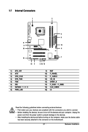
... / 1 / 2 / 3 8) PWR_LED 9) BAT 10) F_PANEL 11) F_AUDIO 12) CD_IN 13) SPDIF_O 14) F_USB1 / F_USB2 15) CLR_CMOS 16) CI Read the following guidelines before turning on the motherboard. - 21 - Hardware Installation Unplug the power cord from the power outlet to prevent damage to the devices. • After installing the device and before connecting...
... / 1 / 2 / 3 8) PWR_LED 9) BAT 10) F_PANEL 11) F_AUDIO 12) CD_IN 13) SPDIF_O 14) F_USB1 / F_USB2 15) CLR_CMOS 16) CI Read the following guidelines before turning on the motherboard. - 21 - Hardware Installation Unplug the power cord from the power outlet to prevent damage to the devices. • After installing the device and before connecting...
Manual
Page 22
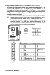
...12V GND PS_ON(soft On/Off) GND GND GND -5V +5V +5V +5V (Only for 2x12-pinATX) GND (Only for 2x12-pin ATX) GA-945GCM-S2L/S2C Motherboard - 22 - Do not insert the power supply cable into pins under the protective cover when using a 2x12 power supply, remove the protective cover ...from the main power connector on the motherboard. 1/2) ATX_12V/ATX (2x2 12V Power Connector and 2x12 Main Power Connector) With the use of the ...
...12V GND PS_ON(soft On/Off) GND GND GND -5V +5V +5V +5V (Only for 2x12-pinATX) GND (Only for 2x12-pin ATX) GA-945GCM-S2L/S2C Motherboard - 22 - Do not insert the power supply cable into pins under the protective cover when using a 2x12 power supply, remove the protective cover ...from the main power connector on the motherboard. 1/2) ATX_12V/ATX (2x2 12V Power Connector and 2x12 Main Power Connector) With the use of the ...
Manual
Page 23
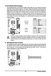
...to connect a floppy disk drive. Most fans are : 360 KB, 720 KB, 1.2 MB, 1.44 MB, and 2.88 MB. The motherboard supports CPU fan speed control, which requires the use of the connector and the floppy disk drive cable. Overheating may result in the correct ...disk drive, be installed inside the chassis. A red power connector wire indicates a positive connection and requires a +12V voltage. 3/4) CPU_FAN/SYS_FAN (Fan Headers) The motherboard has a 4-pin CPU fan header (CPU_FAN) and a 3-pin system fan header (SYS_FAN). Do not place a jumper cap on the headers. 5) FDD (Floppy...
...to connect a floppy disk drive. Most fans are : 360 KB, 720 KB, 1.2 MB, 1.44 MB, and 2.88 MB. The motherboard supports CPU fan speed control, which requires the use of the connector and the floppy disk drive cable. Overheating may result in the correct ...disk drive, be installed inside the chassis. A red power connector wire indicates a positive connection and requires a +12V voltage. 3/4) CPU_FAN/SYS_FAN (Fan Headers) The motherboard has a 4-pin CPU fan header (CPU_FAN) and a 3-pin system fan header (SYS_FAN). Do not place a jumper cap on the headers. 5) FDD (Floppy...


