Manual
Page 3
... respective owners. by GIGA-BYTE TECHNOLOGY CO., LTD as the exclu- Documentation Classifications In order to assist in this product, GIGABYTE provides the following types of this manual are legally registered to use GIGABYTE's unique features, read the User's Manual. „ For instructions on our website. is the property of this manual may...
... respective owners. by GIGA-BYTE TECHNOLOGY CO., LTD as the exclu- Documentation Classifications In order to assist in this product, GIGABYTE provides the following types of this manual are legally registered to use GIGABYTE's unique features, read the User's Manual. „ For instructions on our website. is the property of this manual may...

Manual
Page 5
... ReadyBoost 68 Chapter 5 Appendix ...69 5-1 Configuring Audio Input and Output 69 5-1-1 Configuring 2/4/5.1-Channel Audio 69 5-1-2 Installing the S/PDIFOut Cable (Optional 72 5-1-3 Configuring Microphone Recording 74 5-1-4 Using the Sound Recorder 76 5-2 Troubleshooting 77 5-2-1 Frequently Asked Questions 77 5-2-2 Troubleshooting Procedure 78 Regulatory Statements 80 - 5 -
... ReadyBoost 68 Chapter 5 Appendix ...69 5-1 Configuring Audio Input and Output 69 5-1-1 Configuring 2/4/5.1-Channel Audio 69 5-1-2 Installing the S/PDIFOut Cable (Optional 72 5-1-3 Configuring Microphone Recording 74 5-1-4 Using the Sound Recorder 76 5-2 Troubleshooting 77 5-2-1 Frequently Asked Questions 77 5-2-2 Troubleshooting Procedure 78 Regulatory Statements 80 - 5 -
Manual
Page 8
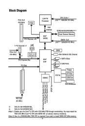
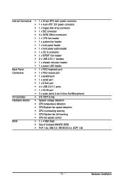
... MIC(Center/Subwoofer Speaker Out) Line-Out(Front Speaker Out) Line-In(Rear Speaker Out) SPDIF Out 2 PCI PCI CLK (33 MHz) Only for GA-945GCM-S2C. (Note 1) Enable use of a 1066/800 MHz FSB CPU is required if you wish to install DDR2 667 MHz memory. - 8 - You must install the FSB 1333 MHz...
... MIC(Center/Subwoofer Speaker Out) Line-Out(Front Speaker Out) Line-In(Rear Speaker Out) SPDIF Out 2 PCI PCI CLK (33 MHz) Only for GA-945GCM-S2C. (Note 1) Enable use of a 1066/800 MHz FSB CPU is required if you wish to install DDR2 667 MHz memory. - 8 - You must install the FSB 1333 MHz...
Manual
Page 9
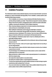
... connectors on the motherboard, make sure the power supply voltage has been set according to the local voltage standard. • Before using the product, please verify that all cables and power connectors of your hardware components are connected. • To prevent damage to the... the AC power by your dealer. Prior to installation, carefully read the user's manual and follow these procedures: • Prior to the use of electrostatic discharge (ESD). These stickers are connected tightly and securely. • When handling the motherboard, avoid touching any installation steps or have...
... connectors on the motherboard, make sure the power supply voltage has been set according to the local voltage standard. • Before using the product, please verify that all cables and power connectors of your hardware components are connected. • To prevent damage to the... the AC power by your dealer. Prior to installation, carefully read the user's manual and follow these procedures: • Prior to the use of electrostatic discharge (ESD). These stickers are connected tightly and securely. • When handling the motherboard, avoid touching any installation steps or have...
Manual
Page 11
...; CPU/System fan speed detection Š CPU overheating warning Š CPU/System fan fail warning Š CPU fan speed control BIOS Š 1 x 4 Mbit flash Š Use of licensed AWARD BIOS Š PnP 1.0a, DMI 2.0, SM BIOS 2.4, ACPI 1.0b - 11 -
...; CPU/System fan speed detection Š CPU overheating warning Š CPU/System fan fail warning Š CPU fan speed control BIOS Š 1 x 4 Mbit flash Š Use of licensed AWARD BIOS Š PnP 1.0a, DMI 2.0, SM BIOS 2.4, ACPI 1.0b - 11 -
Manual
Page 12
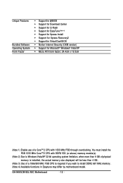
GA-945GCM-S2L/S2C Motherboard - 12 - Unique Features Bundled Software Operating System Form Factor Š Support for @BIOS Š...138; Support for Microsoft® Windows® Vista/XP Š Micro ATX form factor; 24.4cm x 19.3cm (Note 1) Enable use of a CoreTM 2 CPU with DDR2 533 (or above) memory module(s). (Note 2) Due to Windows Vista/XP 32-bit operating system limitation...than 4 GB of physical memory is installed, the actual memory size displayed will be less than 4 GB. (Note 3) Use of a 1066/800 MHz FSB CPU is required if you wish to install DDR2 667 MHz memory. (Note 4) Available ...
GA-945GCM-S2L/S2C Motherboard - 12 - Unique Features Bundled Software Operating System Form Factor Š Support for @BIOS Š...138; Support for Microsoft® Windows® Vista/XP Š Micro ATX form factor; 24.4cm x 19.3cm (Note 1) Enable use of a CoreTM 2 CPU with DDR2 533 (or above) memory module(s). (Note 2) Due to Windows Vista/XP 32-bit operating system limitation...than 4 GB of physical memory is installed, the actual memory size displayed will be less than 4 GB. (Note 3) Use of a 1066/800 MHz FSB CPU is required if you wish to install DDR2 667 MHz memory. (Note 4) Available ...
Manual
Page 15
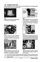
...) on installing the cooler.) Step 5: After the installation, check the back of arrow is to remove the cooler, on the push pins diagonally. Use extreme care when removing the CPU cooler because the thermal grease/tape between the CPU cooler and CPU may damage the CPU. - 15 - Hardware ...the contrary, is complete. 1-3-2 Installing the CPU Cooler Follow the steps below to correctly install the CPU cooler on the motherboard. (The following procedure uses Intel® boxed cooler as the picture above, the installation is to install.) Step 3: Place the cooler atop the CPU, aligning the four ...
...) on installing the cooler.) Step 5: After the installation, check the back of arrow is to remove the cooler, on the push pins diagonally. Use extreme care when removing the CPU cooler because the thermal grease/tape between the CPU cooler and CPU may damage the CPU. - 15 - Hardware ...the contrary, is complete. 1-3-2 Installing the CPU Cooler Follow the steps below to correctly install the CPU cooler on the motherboard. (The following procedure uses Intel® boxed cooler as the picture above, the installation is to install.) Step 3: Place the cooler atop the CPU, aligning the four ...
Manual
Page 16
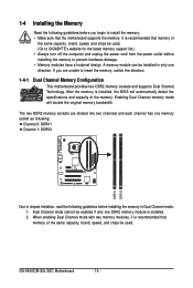
... that memory of the same capacity, brand, speed, and chips be used . (Go to GIGABYTE's website for the latest memory support list.) • Always turn off...mode will automatically detect the specifications and capacity of the same capacity, brand, speed, and chips be used . The two DDR2 memory sockets are unable to insert the memory, switch the direction. 1-4-1 Dual...installed. 2. If you begin to install the memory: • Make sure that memory of the memory. GA-945GCM-S2L/S2C Motherboard - 16 - Dual Channel mode cannot be installed in Dual Channel mode. 1. A memory module can ...
... that memory of the same capacity, brand, speed, and chips be used . (Go to GIGABYTE's website for the latest memory support list.) • Always turn off...mode will automatically detect the specifications and capacity of the same capacity, brand, speed, and chips be used . The two DDR2 memory sockets are unable to insert the memory, switch the direction. 1-4-1 Dual...installed. 2. If you begin to install the memory: • Make sure that memory of the memory. GA-945GCM-S2L/S2C Motherboard - 16 - Dual Channel mode cannot be installed in Dual Channel mode. 1. A memory module can ...
Manual
Page 19
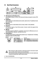
... Hardware Installation The parallel port is occurring • When removing the cable connected to prevent an electrical short inside the cable connector. Use this port. Only for USB devices such as a printer, scanner and etc. USB Port The USB port supports the USB 2.0/1.1 ... keyboard. 1-6 Back Panel Connectors PS/2 Keyboard and PS/2 Mouse Port Use the upper port (green) to connect a PS/2 mouse and the lower port (purple) to 1 Gbps data rate. Serial Port Use the serial port to this port for GA-945GCM-S2L. - 19 - D-Sub Port The D-Sub port supports a...
... Hardware Installation The parallel port is occurring • When removing the cable connected to prevent an electrical short inside the cable connector. Use this port. Only for USB devices such as a printer, scanner and etc. USB Port The USB port supports the USB 2.0/1.1 ... keyboard. 1-6 Back Panel Connectors PS/2 Keyboard and PS/2 Mouse Port Use the upper port (green) to connect a PS/2 mouse and the lower port (purple) to 1 Gbps data rate. Serial Port Use the serial port to this port for GA-945GCM-S2L. - 19 - D-Sub Port The D-Sub port supports a...
Manual
Page 20
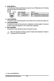
Mic In Jack (Pink) The default Mic in jack. Use this jack. Refer to the instructions on setting up to 100 Mbps data rate. Line Out Jack ...Only for a headphone or 2-channel speaker. Microphones must be used to this audio jack for line in devices such as an optical drive, walkman, etc. The following describes the states of the LAN port LEDs. GA-945GCM-S2L/S2C Motherboard - 20 - Connection/ Speed LED Activity LED Connection/Speed... transmission or receiving is occurring LAN Port Line In Jack (Blue) The default line in jack. Use this audio jack for GA-945GCM-S2C.
Mic In Jack (Pink) The default Mic in jack. Use this jack. Refer to the instructions on setting up to 100 Mbps data rate. Line Out Jack ...Only for a headphone or 2-channel speaker. Microphones must be used to this audio jack for line in devices such as an optical drive, walkman, etc. The following describes the states of the LAN port LEDs. GA-945GCM-S2L/S2C Motherboard - 20 - Connection/ Speed LED Activity LED Connection/Speed... transmission or receiving is occurring LAN Port Line In Jack (Blue) The default line in jack. Use this audio jack for GA-945GCM-S2C.
Manual
Page 22
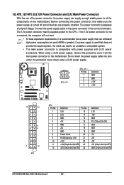
... to the CPU. The power connector possesses a foolproof design. The 12V power connector mainly supplies power to the power connector in the correct orientation. When using a 2x10 power supply. 3 4 1 2 ATX_12V ATX_12V : Pin No. 1 2 3 4 Definition GND GND +12V +12V 12 24 1 13 ATX ATX : Pin No. 1 2 3 4 5 6 7 8 9 10 ...12V GND PS_ON(soft On/Off) GND GND GND -5V +5V +5V +5V (Only for 2x12-pinATX) GND (Only for 2x12-pin ATX) GA-945GCM-S2L/S2C Motherboard - 22 - If a power supply is turned off and all the components on the motherboard. Do not insert the power supply cable into ...
... to the CPU. The power connector possesses a foolproof design. The 12V power connector mainly supplies power to the power connector in the correct orientation. When using a 2x10 power supply. 3 4 1 2 ATX_12V ATX_12V : Pin No. 1 2 3 4 Definition GND GND +12V +12V 12 24 1 13 ATX ATX : Pin No. 1 2 3 4 5 6 7 8 9 10 ...12V GND PS_ON(soft On/Off) GND GND GND -5V +5V +5V +5V (Only for 2x12-pinATX) GND (Only for 2x12-pin ATX) GA-945GCM-S2L/S2C Motherboard - 22 - If a power supply is turned off and all the components on the motherboard. Do not insert the power supply cable into ...
Manual
Page 23
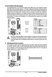
...design. A red power connector wire indicates a positive connection and requires a +12V voltage. The motherboard supports CPU fan speed control, which requires the use of a CPU fan with color-coded power connector wires. Before connecting a floppy disk drive, be sure to the CPU or the system may ... jumper cap on the headers. 5) FDD (Floppy Disk Drive Connector) This connector is recommended that a system fan be sure to connect it is used to prevent your CPU and system from overheating. The pin 1 of the connector and the floppy disk drive cable. Each fan header supplies a ...
...design. A red power connector wire indicates a positive connection and requires a +12V voltage. The motherboard supports CPU fan speed control, which requires the use of a CPU fan with color-coded power connector wires. Before connecting a floppy disk drive, be sure to the CPU or the system may ... jumper cap on the headers. 5) FDD (Floppy Disk Drive Connector) This connector is recommended that a system fan be sure to connect it is used to prevent your CPU and system from overheating. The pin 1 of the connector and the floppy disk drive cable. Each fan header supplies a ...
Manual
Page 25
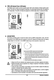
... drops to replace the battery by removing the battery: 1. Danger of explosion if the battery is replaced with an equivalent one minute. (Or use a metal object like a screwdriver to touch the positive and negative terminals of the battery (the positive side should face up). •...; Used batteries must be lost. Replace the battery. 4. 8) PWR_LED (System Power LED Header) This header can be used to connect a system power LED on when the system is turned off when the system is ...
... drops to replace the battery by removing the battery: 1. Danger of explosion if the battery is replaced with an equivalent one minute. (Or use a metal object like a screwdriver to touch the positive and negative terminals of the battery (the positive side should face up). •...; Used batteries must be lost. Replace the battery. 4. 8) PWR_LED (System Power LED Header) This header can be used to connect a system power LED on when the system is turned off when the system is ...
Manual
Page 26
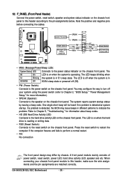
... Message LED/ Power/ Sleep LED SPEAK- 20 19 SPEAK+ PWPW+ MSGMSG+ 21 NCRES+ RES- The S0 On LED is in S1 sleep state. GA-945GCM-S2L/S2C Motherboard - 26 - HDHD+ Reset Switch IDE Hard Disk Active LED • MSG (Message/Power/Sleep LED): System Status LED Connects to turn off... is on the chassis front panel. You may configure the way to the power status indicator on the chassis front panel. When connecting your system using the power switch (refer to Chapter 2, "BIOS Setup," "Power Management Setup," for information about beep codes. • HD (IDE Hard Drive Activity ...
... Message LED/ Power/ Sleep LED SPEAK- 20 19 SPEAK+ PWPW+ MSGMSG+ 21 NCRES+ RES- The S0 On LED is in S1 sleep state. GA-945GCM-S2L/S2C Motherboard - 26 - HDHD+ Reset Switch IDE Hard Disk Active LED • MSG (Message/Power/Sleep LED): System Status LED Connects to turn off... is on the chassis front panel. You may configure the way to the power status indicator on the chassis front panel. When connecting your system using the power switch (refer to Chapter 2, "BIOS Setup," "Power Management Setup," for information about beep codes. • HD (IDE Hard Drive Activity ...
Manual
Page 27
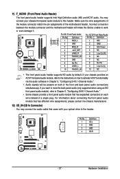
... motherboard header will be present on each wire instead of the motherboard header. If you want to mute the back panel audio (only supported when using an HD front panel audio module), refer to Chapter 5, "Configuring 2/4/5.1-Channel Audio." • Some chassis provide a front panel audio module that came with your chassis...
... motherboard header will be present on each wire instead of the motherboard header. If you want to mute the back panel audio (only supported when using an HD front panel audio module), refer to Chapter 5, "Configuring 2/4/5.1-Channel Audio." • Some chassis provide a front panel audio module that came with your chassis...
Manual
Page 29
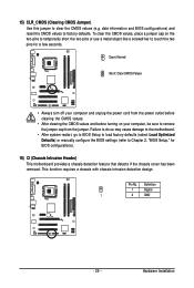
15) CLR_CMOS (Clearing CMOS Jumper) Use this jumper to factory defaults. date information and BIOS configurations) and reset the CMOS values to clear the CMOS values (e.g. Open: Normal Short: Clear CMOS ... before clearing the CMOS values. • After clearing the CMOS values and before turning on the two pins to temporarily short the two pins or use a metal object like a screwdriver to touch the two pins for BIOS configurations). 16) CI (Chassis Intrusion Header) This motherboard provides a chassis detection feature that detects...
15) CLR_CMOS (Clearing CMOS Jumper) Use this jumper to factory defaults. date information and BIOS configurations) and reset the CMOS values to clear the CMOS values (e.g. Open: Normal Short: Clear CMOS ... before clearing the CMOS values. • After clearing the CMOS values and before turning on the two pins to temporarily short the two pins or use a metal object like a screwdriver to touch the two pins for BIOS configurations). 16) CI (Chassis Intrusion Header) This motherboard provides a chassis detection feature that detects...
Manual
Page 31
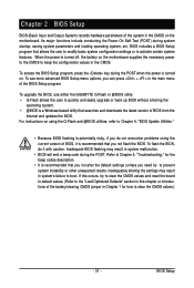
...; @BIOS is recommended that searches and downloads the latest version of the battery/clearing CMOS jumper in the CMOS. To upgrade the BIOS, use either the GIGABYTE Q-Flash or @BIOS utility. • Q-Flash allows the user to the "Load Optimized Defaults" section in this chapter or introductions of... advanced BIOS Setup menu options, you need to) to clear the CMOS values.) - 31 - To flash the BIOS, do not encounter problems using the Q-Flash and @BIOS utilities, refer to activate certain system features. Its major functions include conducting the Power-On Self-Test (POST) during ...
...; @BIOS is recommended that searches and downloads the latest version of the battery/clearing CMOS jumper in the CMOS. To upgrade the BIOS, use either the GIGABYTE Q-Flash or @BIOS utility. • Q-Flash allows the user to the "Load Optimized Defaults" section in this chapter or introductions of... advanced BIOS Setup menu options, you need to) to clear the CMOS values.) - 31 - To flash the BIOS, do not encounter problems using the Q-Flash and @BIOS utilities, refer to activate certain system features. Its major functions include conducting the Power-On Self-Test (POST) during ...
Manual
Page 32
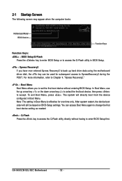
...BIOS Setup. : Xpress Recovery2 If you to set the first boot device without having to access the Q-Flash utility directly without entering BIOS Setup. GA-945GCM-S2L/S2C Motherboard - 32 - Motherboard Model BIOS Version Award Modular BIOS v6.00PG, An Energy Star Ally Copyright (C) 1984-2007, Award Software, Inc....to change the first boot device setting as needed. : Q-Flash Press the key to enter BIOS Setup first. The system will still be used for one time only. You can be based on BIOS Setup settings. Note: The setting in Boot Menu. After system restart, the device...
...BIOS Setup. : Xpress Recovery2 If you to set the first boot device without having to access the Q-Flash utility directly without entering BIOS Setup. GA-945GCM-S2L/S2C Motherboard - 32 - Motherboard Model BIOS Version Award Modular BIOS v6.00PG, An Energy Star Ally Copyright (C) 1984-2007, Award Software, Inc....to change the first boot device setting as needed. : Q-Flash Press the key to enter BIOS Setup first. The system will still be used for one time only. You can be based on BIOS Setup settings. Note: The setting in Boot Menu. After system restart, the device...

Manual
Page 33
... + to access more advanced options. • When the system is displayed on the screen. Press to accept or enter a sub-menu. (Sample BIOS Version: GA-945GCM-S2L E10) CMOS Setup Utility-Copyright (C) 1984-2007 Award Software ` Standard CMOS Features ` Advanced BIOS Features ` Integrated Peripherals ` Power Management Setup ` PnP/PCI ... make changes Decrease the numeric value or make changes Show descriptions of the function keys Move cursor to display a help screen. Use arrow keys to move among the items and press to exit the help screen (General Help) of the Main Menu.
... + to access more advanced options. • When the system is displayed on the screen. Press to accept or enter a sub-menu. (Sample BIOS Version: GA-945GCM-S2L E10) CMOS Setup Utility-Copyright (C) 1984-2007 Award Software ` Standard CMOS Features ` Advanced BIOS Features ` Integrated Peripherals ` Power Management Setup ` PnP/PCI ... make changes Decrease the numeric value or make changes Show descriptions of the function keys Move cursor to display a help screen. Use arrow keys to move among the items and press to exit the help screen (General Help) of the Main Menu.
Manual
Page 34
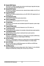
... Save all the changes made in the BIOS Setup program to the CMOS and exit BIOS Setup. (Pressing can also carry out this task.) GA-945GCM-S2L/S2C Motherboard - 34 - Pressing to the confirmation message will exit BIOS Setup. (Pressing can also carry out this task.) „ Exit Without ...defaults are factory settings for optimal-performance system operations. „ Set Supervisor Password Change, set , or disable password. „ Standard CMOS Features Use this menu to configure the system time and date, hard drive types, floppy disk drive types, and the type of errors that stop the system...
... Save all the changes made in the BIOS Setup program to the CMOS and exit BIOS Setup. (Pressing can also carry out this task.) GA-945GCM-S2L/S2C Motherboard - 34 - Pressing to the confirmation message will exit BIOS Setup. (Pressing can also carry out this task.) „ Exit Without ...defaults are factory settings for optimal-performance system operations. „ Set Supervisor Password Change, set , or disable password. „ Standard CMOS Features Use this menu to configure the system time and date, hard drive types, floppy disk drive types, and the type of errors that stop the system...

