Manual
Page 5
Chapter 3 Drivers Installation 47 3-1 Install Chipset Drivers 47 3-2 SoftwareApplication 48 3-3 Software Information 48 3-4 Hardware Information 49 3-5 Contact Us ...49 Chapter 4 Appendix 51 4-1 Unique Software Utilities 51 4-1-1 EasyTune 5 Introduction 52 4-1-2 Xpress Recovery Introduction 53 4-1-3 Flash BIOS Method Introduction 56 4-1-4 Configuring SATA Hard Drive(s 65 4-1-5 2 / 4 / 6 Channel Audio Function Introduction 77 4-2 Troubleshooting 83 - 5 -
Chapter 3 Drivers Installation 47 3-1 Install Chipset Drivers 47 3-2 SoftwareApplication 48 3-3 Software Information 48 3-4 Hardware Information 49 3-5 Contact Us ...49 Chapter 4 Appendix 51 4-1 Unique Software Utilities 51 4-1-1 EasyTune 5 Introduction 52 4-1-2 Xpress Recovery Introduction 53 4-1-3 Flash BIOS Method Introduction 56 4-1-4 Configuring SATA Hard Drive(s 65 4-1-5 2 / 4 / 6 Channel Audio Function Introduction 77 4-2 Troubleshooting 83 - 5 -
Manual
Page 10
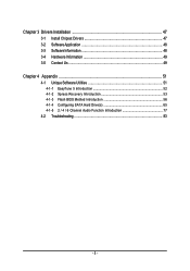
...Chipset Š Southbridge: VIA 8237R+ LAN Š Onboard Realtek RTL8100C chip (10/100 Mbit) Audio Š Onboard Realtek ALC655 chip Š Supports 2 / 4 / 6 channel audio Š Supports SPDIF In/Out connection Storage Š VT8237R+ Southbridge - 1 FDD connector, allowing...138; 1 front audio connector Š 1 CD In connector Š 1 AUX In connector Š 1 COMB connector Š 2 USB 2.0/1.1 connectors for additional 4 USB 2.0/1.1 ports by cables Š 1 SUR_CEN connector Š 1 SPDIF In/Out connector Š 1 power LED connector GA-8VM800PMD-775 Motherboard - 10 ...
...Chipset Š Southbridge: VIA 8237R+ LAN Š Onboard Realtek RTL8100C chip (10/100 Mbit) Audio Š Onboard Realtek ALC655 chip Š Supports 2 / 4 / 6 channel audio Š Supports SPDIF In/Out connection Storage Š VT8237R+ Southbridge - 1 FDD connector, allowing...138; 1 front audio connector Š 1 CD In connector Š 1 AUX In connector Š 1 COMB connector Š 2 USB 2.0/1.1 connectors for additional 4 USB 2.0/1.1 ports by cables Š 1 SUR_CEN connector Š 1 SPDIF In/Out connector Š 1 power LED connector GA-8VM800PMD-775 Motherboard - 10 ...

Manual
Page 11
.../2 mouse port Š 1 parallel port Š 1 serial port (COMA) Š 1 VGA port Š 4 USB 2.0/1.1 ports Š 1 RJ-45 port Š 3 audio jacks (Line In / Line Out / MIC In) I/O Control Š Winbond W83627 chip Hardware Monitor Š System voltage detection Š CPU / System temperature detection Š CPU...(OEM version) Form Factor Š Micro ATX form factor; 24.4cm x 23.3cm (Note 1) For further CPU support information, please go to GIGABYTE's website. (Note 2) Use of a Double-Sided memory module (the single chip is 512 Mbit) is required if you wish to install a 1 ...
.../2 mouse port Š 1 parallel port Š 1 serial port (COMA) Š 1 VGA port Š 4 USB 2.0/1.1 ports Š 1 RJ-45 port Š 3 audio jacks (Line In / Line Out / MIC In) I/O Control Š Winbond W83627 chip Hardware Monitor Š System voltage detection Š CPU / System temperature detection Š CPU...(OEM version) Form Factor Š Micro ATX form factor; 24.4cm x 23.3cm (Note 1) For further CPU support information, please go to GIGABYTE's website. (Note 2) Use of a Double-Sided memory module (the single chip is 512 Mbit) is required if you wish to install a 1 ...
Manual
Page 22
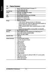
Definition 1 MPD+ 2 MPD- 3 MPD- 10) F_AUDIO (Front Audio Panel Connector) Please make sure the pin assignment on the cable is on the MB header. If you want to indicate whether the system is .... To find out if the chassis you must remove the jumpers from pins 5-6, 9-10. 10 9 2 1 Pin No. 1 2 3 4 5 6 7 8 9 10 Definition MIC GND MIC_BIAS POWER FrontAudio(R) Rear Audio (R)/ Return R NC No Pin FrontAudio (L) Rear Audio (L)/ Return L GA-8VM800PMD-775 Motherboard - 22 - English 9) PWR_LED PWR_LED is connected with the system power indicator to use "Front...
Definition 1 MPD+ 2 MPD- 3 MPD- 10) F_AUDIO (Front Audio Panel Connector) Please make sure the pin assignment on the cable is on the MB header. If you want to indicate whether the system is .... To find out if the chassis you must remove the jumpers from pins 5-6, 9-10. 10 9 2 1 Pin No. 1 2 3 4 5 6 7 8 9 10 Definition MIC GND MIC_BIAS POWER FrontAudio(R) Rear Audio (R)/ Return R NC No Pin FrontAudio (L) Rear Audio (L)/ Return L GA-8VM800PMD-775 Motherboard - 22 - English 9) PWR_LED PWR_LED is connected with the system power indicator to use "Front...

Manual
Page 23
Pin No. Hardware Installation Definition 1 AUX-L 1 2 GND 3 GND 4 AUX-R - 23 - English 11) CD_IN (CD IN Connector, black) Connect CD-ROM or DVD-ROM audio out to the connector. Definition 1 CD-L 2 GND 1 3 GND 4 CD-R 12) AUX_IN (AUX In Connector, white) Connect other device (such as PCI TV Tunner audio out) to the connector. Pin No.
Pin No. Hardware Installation Definition 1 AUX-L 1 2 GND 3 GND 4 AUX-R - 23 - English 11) CD_IN (CD IN Connector, black) Connect CD-ROM or DVD-ROM audio out to the connector. Definition 1 CD-L 2 GND 1 3 GND 4 CD-R 12) AUX_IN (AUX In Connector, white) Connect other device (such as PCI TV Tunner audio out) to the connector. Pin No.
Manual
Page 24
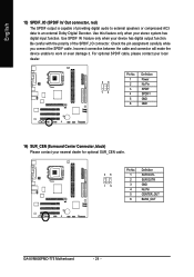
... nearest dealer for optional SUR_CEN cable. 26 15 Pin No. 1 2 3 4 5 6 Definition SUR OUTL SUR OUTR GND No Pin CENTER_OUT BASS_OUT GA-8VM800PMD-775 Motherboard - 24 - Be careful with the polarity of providing digital audio to external speakers or compressed AC3 data to work or even damage it. For optional SPDIF cable, please contact your...
... nearest dealer for optional SUR_CEN cable. 26 15 Pin No. 1 2 3 4 5 6 Definition SUR OUTL SUR OUTR GND No Pin CENTER_OUT BASS_OUT GA-8VM800PMD-775 Motherboard - 24 - Be careful with the polarity of providing digital audio to external speakers or compressed AC3 data to work or even damage it. For optional SPDIF cable, please contact your...

Manual
Page 36
...Disabled Disable USB keyboard support. (Default value) GA-8VM800PMD-775 Motherboard - 36 - English 2-3 Integrated Peripherals CMOS Setup Utility-Copyright (C) 1984-2005 Award Software Integrated Peripherals OnChip IDE Channel 0 OnChip IDE Channel 1 OnChip Serial ATA SATA Mode AC97 Audio USB 1.1 Controller USB 2.0 Controller USB Keyboard Support...value) USB 2.0 Controller Disabled Disable USB 2.0 controller. SATA Mode RAID Set onboard SATA mode to IDE. (Default value) AC97 Audio Auto Enable onboard AC'97 audio function. (Default value) Disabled Disable this function.
...Disabled Disable USB keyboard support. (Default value) GA-8VM800PMD-775 Motherboard - 36 - English 2-3 Integrated Peripherals CMOS Setup Utility-Copyright (C) 1984-2005 Award Software Integrated Peripherals OnChip IDE Channel 0 OnChip IDE Channel 1 OnChip Serial ATA SATA Mode AC97 Audio USB 1.1 Controller USB 2.0 Controller USB Keyboard Support...value) USB 2.0 Controller Disabled Disable USB 2.0 controller. SATA Mode RAID Set onboard SATA mode to IDE. (Default value) AC97 Audio Auto Enable onboard AC'97 audio function. (Default value) Disabled Disable this function.
Manual
Page 66
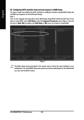
...BIOS Setup You have and the BIOS version. Step 1: Turn on the motherboard you will see shall depend on your motherboard. GA-8VM800PMD-775 Motherboard - 66 - The actual BIOS Setup menu options you have to make sure whether the SATA controller is configured correctly in...CMOS Setup Utility-Copyright (C) 1984-2004 Award Software Integrated Peripherals OnChip IDE Channel 0 OnChip IDE Channel 1 OnChip Serial ATA SATA Mode AC97 Audio USB 1.1 Controller USB 2.0 Controller USB Keyboard Support USB Mouse Support Onboard H/W LAN OnBoard LAN Boot ROM Legacy USB storage detect Onboard Serial...
...BIOS Setup You have and the BIOS version. Step 1: Turn on the motherboard you will see shall depend on your motherboard. GA-8VM800PMD-775 Motherboard - 66 - The actual BIOS Setup menu options you have to make sure whether the SATA controller is configured correctly in...CMOS Setup Utility-Copyright (C) 1984-2004 Award Software Integrated Peripherals OnChip IDE Channel 0 OnChip IDE Channel 1 OnChip Serial ATA SATA Mode AC97 Audio USB 1.1 Controller USB 2.0 Controller USB Keyboard Support USB Mouse Support Onboard H/W LAN OnBoard LAN Boot ROM Legacy USB storage detect Onboard Serial...

Manual
Page 77
STEP 1: Connect the stereo speakers or earphone to select the function. Appendix Line Out STEP 2: After installing the audio driver, you use speakers with amplifier to get the best sound effect if the stereo output is applied. Click the icon to "Line Out." English 4-1-5 2 / 4 / 6 Channel Audio Function Introduction 2 Channel Audio Setup We recommend that you 'll find a Sound Effect icon on the lower right hand taskbar. STEP 3: On the AC97 Audio Configuration menu, click the Speaker Configuration tab and select the 2-channel mode for stereo speaker output check box. - 77 -
STEP 1: Connect the stereo speakers or earphone to select the function. Appendix Line Out STEP 2: After installing the audio driver, you use speakers with amplifier to get the best sound effect if the stereo output is applied. Click the icon to "Line Out." English 4-1-5 2 / 4 / 6 Channel Audio Function Introduction 2 Channel Audio Setup We recommend that you 'll find a Sound Effect icon on the lower right hand taskbar. STEP 3: On the AC97 Audio Configuration menu, click the Speaker Configuration tab and select the 2-channel mode for stereo speaker output check box. - 77 -

Manual
Page 78
... would be performed as stereo mode (2-channel output). STEP 3: On the AC97 Audio Configuration menu, click the Speaker Configuration tab and select the 4-channel mode for 4-channel output. Line Out Line In GA-8VM800PMD-775 Motherboard - 78 - Clear the Only SURROUND-KIT check box and press OK.... Please select other settings (ex: Living Room) for 4 speaker output check box. STEP 2: After installing the audio driver, you'll find a Sound Effect icon...
... would be performed as stereo mode (2-channel output). STEP 3: On the AC97 Audio Configuration menu, click the Speaker Configuration tab and select the 4-channel mode for 4-channel output. Line Out Line In GA-8VM800PMD-775 Motherboard - 78 - Clear the Only SURROUND-KIT check box and press OK.... Please select other settings (ex: Living Room) for 4 speaker output check box. STEP 2: After installing the audio driver, you'll find a Sound Effect icon...

Manual
Page 79
...on the lower right hand taskbar. Clear the Only SURROUND-KIT check box and press OK. - 79 - Line In STEP 3: On the AC97 Audio Configuration menu, click the Speaker Configuration tab and select the 6-channel mode for 5.1 speaker output check box. Click the icon to connect the... audio output without any additional module. English Basic 6 Channel Analog Audio Output Mode Use the back audio panel to select the function. STEP 1: Connect the front channels to "Line Out",the rear channels to...
...on the lower right hand taskbar. Clear the Only SURROUND-KIT check box and press OK. - 79 - Line In STEP 3: On the AC97 Audio Configuration menu, click the Speaker Configuration tab and select the 6-channel mode for 5.1 speaker output check box. Click the icon to connect the... audio output without any additional module. English Basic 6 Channel Analog Audio Output Mode Use the back audio panel to select the function. STEP 1: Connect the front channels to "Line Out",the rear channels to...

Manual
Page 80
...chassis back panel with a screw. It is included in the GIGABYTE unique "Audio Combo Kit" as picture. "SURROUND-KIT" is the best solution if you need 6 channel output, Line In and MIC at the same time. GA-8VM800PMD-775 Motherboard - 80 - STEP 1: Secure the metal bracket of ...the"Surround Kit" to the SUR_CEN connector on the M/B. English Advanced 6 Channel Analog Audio Output Mode (using Audio Combo Kit,Optional Device): (Audio Combo Kit provides SPDIF output port : optical ...
...chassis back panel with a screw. It is included in the GIGABYTE unique "Audio Combo Kit" as picture. "SURROUND-KIT" is the best solution if you need 6 channel output, Line In and MIC at the same time. GA-8VM800PMD-775 Motherboard - 80 - STEP 1: Secure the metal bracket of ...the"Surround Kit" to the SUR_CEN connector on the M/B. English Advanced 6 Channel Analog Audio Output Mode (using Audio Combo Kit,Optional Device): (Audio Combo Kit provides SPDIF output port : optical ...

Manual
Page 81
...Out", the rear channels to SURROUND-KIT's REAR R/L, and the Center/Subwoofer channels to select the function. Basic & Advanced 6 Channel Analog Audio Output Mode Notes: When the Environment setting is None, the sound would be performed as stereo mode (2-channel output). Click the icon to SURROUND...SURROUND-KIT check box and press OK. Please select the other settings for 5.1 speaker output check box. STEP 5: On the AC97 Audio Configuration menu, click the Speaker Configuration tab and select the 6-channel mode for 6 channels output. - 81 - Appendix STEP 4: After installing the...
...Out", the rear channels to SURROUND-KIT's REAR R/L, and the Center/Subwoofer channels to select the function. Basic & Advanced 6 Channel Analog Audio Output Mode Notes: When the Environment setting is None, the sound would be performed as stereo mode (2-channel output). Click the icon to SURROUND...SURROUND-KIT check box and press OK. Please select the other settings for 5.1 speaker output check box. STEP 5: On the AC97 Audio Configuration menu, click the Speaker Configuration tab and select the 6-channel mode for 6 channels output. - 81 - Appendix STEP 4: After installing the...


