Manual
Page 4
...Heatsink 12 1-3-1 Installation of the CPU 12 1-3-2 Installation of the Heatsink 13 1-4 Installation of Memory 14 1-5 Installation of Expansion Cards 15 1-6 I/O Back Panel Introduction 16 1-7 Connectors Introduction 17 Chapter 2 BIOS Setup 29 The Main Menu (For example: BIOS Ver. : D1 30 2-1 Standard CMOS Features 32 2-2 Advanced BIOS Features 34 2-3 IntegratedPeripherals 36 2-4 Power Management Setup 38 2-5 PnP/PCI Configurations 40 2-6 PC Health Status 41 2-7 Frequency / Voltage Control 42 2-8 Load Fail-Safe Defaults 44 2-9 Load Optimized Defaults 44 2-10 Set Supervisor/User...
...Heatsink 12 1-3-1 Installation of the CPU 12 1-3-2 Installation of the Heatsink 13 1-4 Installation of Memory 14 1-5 Installation of Expansion Cards 15 1-6 I/O Back Panel Introduction 16 1-7 Connectors Introduction 17 Chapter 2 BIOS Setup 29 The Main Menu (For example: BIOS Ver. : D1 30 2-1 Standard CMOS Features 32 2-2 Advanced BIOS Features 34 2-3 IntegratedPeripherals 36 2-4 Power Management Setup 38 2-5 PnP/PCI Configurations 40 2-6 PC Health Status 41 2-7 Frequency / Voltage Control 42 2-8 Load Fail-Safe Defaults 44 2-9 Load Optimized Defaults 44 2-10 Set Supervisor/User...
Manual
Page 10
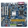
... slot Š 3 PCI slots Internal Connectors Š 1 20-pin ATX power connector Š 1 4-pin ATX 12V power connector Š 1 floppy connector Š 2 IDE connectors Š 2 SATA connectors Š 1 CPU fan connector Š 1 system fan connector Š 1 front panel connector Š 1 front audio connector Š 1 CD In connector Š 1 AUX In connector Š 1 COMB connector Š 2 USB 2.0/1.1 connectors for additional 4 USB 2.0/1.1 ports by cables Š 1 SUR_CEN connector Š 1 SPDIF In/Out connector Š 1 power LED connector GA-8VM800PMD-775 Motherboard...
... slot Š 3 PCI slots Internal Connectors Š 1 20-pin ATX power connector Š 1 4-pin ATX 12V power connector Š 1 floppy connector Š 2 IDE connectors Š 2 SATA connectors Š 1 CPU fan connector Š 1 system fan connector Š 1 front panel connector Š 1 front audio connector Š 1 CD In connector Š 1 AUX In connector Š 1 COMB connector Š 2 USB 2.0/1.1 connectors for additional 4 USB 2.0/1.1 ports by cables Š 1 SUR_CEN connector Š 1 SPDIF In/Out connector Š 1 power LED connector GA-8VM800PMD-775 Motherboard...
Manual
Page 20
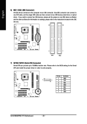
... on settings, please refer to the instructions located on one IDE cable, and the single IDE cable can provide up to the computer via an IDE connector. Definition 1 GND 1 7 2 TXP 3 TXN 4 GND 5 RXN 6 RXP 7 GND GA-8VM800PMD-775 Motherboard - 20 - One IDE connector can connect to one IDE device as Master and the other as Slave (for the Serial ATA and install the proper driver in order to two IDE devices (hard drive or optical drive). Pin...
... on settings, please refer to the instructions located on one IDE cable, and the single IDE cable can provide up to the computer via an IDE connector. Definition 1 GND 1 7 2 TXP 3 TXN 4 GND 5 RXN 6 RXP 7 GND GA-8VM800PMD-775 Motherboard - 20 - One IDE connector can connect to one IDE device as Master and the other as Slave (for the Serial ATA and install the proper driver in order to two IDE devices (hard drive or optical drive). Pin...

Manual
Page 21
...Data(-) Open: Normal Close: Reset Hardware System Open: Normal Close: Power On/Off Pin 1: LED anode(+) Pin 2: LED cathode(-) NC - 21 - Hardware Installation RESRES+ NC HD (IDE Hard Disk Active LED) SPEAK (Speaker Connector) RES (Reset Switch) PW (Power Switch) MSG (Message LED/Power/Sleep LED) NC Reset Switch IDE Hard Disk Active LED Pin 1: LED anode(+) Pin 2: LED cathode(-) Pin 1: Power Pin 2- Message LED/ Power/ Sleep LED Speaker Connector Power Switch MSG+ MSG- English 8) F_PANEL (Front Panel Connector) Please connect the power LED, PC speaker, reset switch and power switch etc.
...Data(-) Open: Normal Close: Reset Hardware System Open: Normal Close: Power On/Off Pin 1: LED anode(+) Pin 2: LED cathode(-) NC - 21 - Hardware Installation RESRES+ NC HD (IDE Hard Disk Active LED) SPEAK (Speaker Connector) RES (Reset Switch) PW (Power Switch) MSG (Message LED/Power/Sleep LED) NC Reset Switch IDE Hard Disk Active LED Pin 1: LED anode(+) Pin 2: LED cathode(-) Pin 1: Power Pin 2- Message LED/ Power/ Sleep LED Speaker Connector Power Switch MSG+ MSG- English 8) F_PANEL (Front Panel Connector) Please connect the power LED, PC speaker, reset switch and power switch etc.
Manual
Page 24
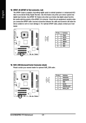
.... Use this feature only when your device has digital output function. For optional SPDIF cable, please contact your local dealer. 26 15 Pin No. 1 2 3 4 5 6 Definition Power No Pin SPDIF SPDIFI GND GND 14) SUR_CEN (Surround Center Connector, black) Please contact your nearest dealer for optional SUR_CEN cable. 26 15 Pin No. 1 2 3 4 5 6 Definition SUR OUTL SUR OUTR GND No Pin CENTER_OUT BASS_OUT GA-8VM800PMD-775 Motherboard - 24 - Incorrect connection between...
.... Use this feature only when your device has digital output function. For optional SPDIF cable, please contact your local dealer. 26 15 Pin No. 1 2 3 4 5 6 Definition Power No Pin SPDIF SPDIFI GND GND 14) SUR_CEN (Surround Center Connector, black) Please contact your nearest dealer for optional SUR_CEN cable. 26 15 Pin No. 1 2 3 4 5 6 Definition SUR OUTL SUR OUTR GND No Pin CENTER_OUT BASS_OUT GA-8VM800PMD-775 Motherboard - 24 - Incorrect connection between...
Manual
Page 30
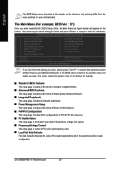
... ` Power Management Setup ` PnP/PCI Configurations ` PC Health Status ` Frequency/Voltage Control Esc: Quit F8: Q-Flash Load Fail-Safe Defaults Load Optimized Defaults Set Supervisor Password Set User Password Save & Exit Setup Exit Without Saving KLJI: Select Item F10: Save & Exit Setup Time, Date, Hard Disk Type... The Main Menu (For example: BIOS Ver. : D1) Once you want, please press "Ctrl+F1" to accept or enter the sub-menu. If you can't find the setting you enter Award BIOS CMOS Setup Utility, the Main Menu (as usual. Use...
... ` Power Management Setup ` PnP/PCI Configurations ` PC Health Status ` Frequency/Voltage Control Esc: Quit F8: Q-Flash Load Fail-Safe Defaults Load Optimized Defaults Set Supervisor Password Set User Password Save & Exit Setup Exit Without Saving KLJI: Select Item F10: Save & Exit Setup Time, Date, Hard Disk Type... The Main Menu (For example: BIOS Ver. : D1) Once you want, please press "Ctrl+F1" to accept or enter the sub-menu. If you can't find the setting you enter Award BIOS CMOS Setup Utility, the Main Menu (as usual. Use...
Manual
Page 32
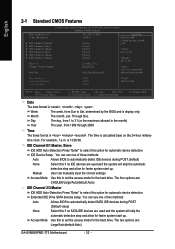
...- Manual User can use one of three methods: Auto Allows BIOS to set the access mode for automatic device detection. English 2-1 Standard CMOS Features CMOS Setup Utility-Copyright (C) 1984-2005 Award Software Standard CMOS Features Date (mm:dd:yy) Time (hh:mm:ss) ` IDE Channel 0 Master ` IDE Channel 0 Slave ` IDE Channel 1 Master ` IDE Channel 1 Slave ` IDE Channel 2 Master ` IDE Channel 3 Master Drive A Floppy 3 Mode Support Halt On Wed, Nov 2 2005 10:40:9 [None] [None] [None] [None] [None] [None] [1.44M, 3.5"] [Disabled] [All, But Keyboard] Item...
...- Manual User can use one of three methods: Auto Allows BIOS to set the access mode for automatic device detection. English 2-1 Standard CMOS Features CMOS Setup Utility-Copyright (C) 1984-2005 Award Software Standard CMOS Features Date (mm:dd:yy) Time (hh:mm:ss) ` IDE Channel 0 Master ` IDE Channel 0 Slave ` IDE Channel 1 Master ` IDE Channel 1 Slave ` IDE Channel 2 Master ` IDE Channel 3 Master Drive A Floppy 3 Mode Support Halt On Wed, Nov 2 2005 10:40:9 [None] [None] [None] [None] [None] [None] [1.44M, 3.5"] [Disabled] [All, But Keyboard] Item...

Manual
Page 37
....9 Set EPP Mode to EPP1.7. (Default value) Set EPP Mode to invoke the boot ROM of the onboard LAN chip. Onboard Serial Port 1 Auto BIOS will automatically set up the Serial port 2 address. Onboard Parallel Port Disabled Disable onboard LPT port. 378/IRQ7 278/IRQ5 Enable onboard LPT port and address is 378/IRQ7. (Default value) Enable onboard LPT port and address is 278/IRQ5. 3BC/IRQ7 Enable onboard LPT port and address is 3F8/IRQ4. English USB Mouse Support Enabled Enable USB mouse support. ECP Using Parallel port as Enhanced Parallel Port. OnBoard LAN Boot ROM...
....9 Set EPP Mode to EPP1.7. (Default value) Set EPP Mode to invoke the boot ROM of the onboard LAN chip. Onboard Serial Port 1 Auto BIOS will automatically set up the Serial port 2 address. Onboard Parallel Port Disabled Disable onboard LPT port. 378/IRQ7 278/IRQ5 Enable onboard LPT port and address is 378/IRQ7. (Default value) Enable onboard LPT port and address is 278/IRQ5. 3BC/IRQ7 Enable onboard LPT port and address is 3F8/IRQ4. English USB Mouse Support Enabled Enable USB mouse support. ECP Using Parallel port as Enhanced Parallel Port. OnBoard LAN Boot ROM...
Manual
Page 42
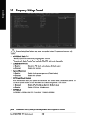
... Spectrum CPU Host Clock Control x CPU Clock DRAM Clock AGP OverVoltage Control DIMM OverVoltage Control [22X] [Enabled] [Enabled] [Disabled] 133 [By SPD] [Audo] [Auto] Item Help Menu Level` KLJI: Move Enter: Select F5: Previous Values +/-/PU/PD: Value F10: Save ESC: Exit F6: Fail-Safe Defaults F7: Optimized Defaults F1: General Help Incorrect using these features may cause your system is not changeable. GA-8VM800PMD-775 Motherboard - 42 - CPU Clock Ratio (Note) This setup option will display "Locked...
... Spectrum CPU Host Clock Control x CPU Clock DRAM Clock AGP OverVoltage Control DIMM OverVoltage Control [22X] [Enabled] [Enabled] [Disabled] 133 [By SPD] [Audo] [Auto] Item Help Menu Level` KLJI: Move Enter: Select F5: Previous Values +/-/PU/PD: Value F10: Save ESC: Exit F6: Fail-Safe Defaults F7: Optimized Defaults F1: General Help Incorrect using these features may cause your system is not changeable. GA-8VM800PMD-775 Motherboard - 42 - CPU Clock Ratio (Note) This setup option will display "Locked...
Manual
Page 45
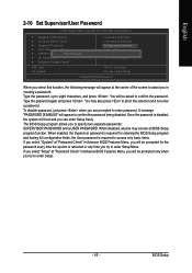
... the center of the screen to assist you in creating a password. English 2-10 Set Supervisor/User Password CMOS Setup Utility-Copyright (C) 1984-2005 Award Software ` Standard CMOS Features ` Advanced BIOS Features ` Integrated Peripherals ` Power Management Setup ` PnP/PCI ConfigurationEsnter Password: ` PC Health Status ` Frequency/Voltage Control Load Fail-Safe Defaults Load Optimized Defaults Set Supervisor Password Set User Password Save & Exit Setup Exit Without Saving ESC: Quit F8: Q-Flash KLJI: Select Item F10: Save & Exit Setup Change/Set/Disable Password When you select...
... the center of the screen to assist you in creating a password. English 2-10 Set Supervisor/User Password CMOS Setup Utility-Copyright (C) 1984-2005 Award Software ` Standard CMOS Features ` Advanced BIOS Features ` Integrated Peripherals ` Power Management Setup ` PnP/PCI ConfigurationEsnter Password: ` PC Health Status ` Frequency/Voltage Control Load Fail-Safe Defaults Load Optimized Defaults Set Supervisor Password Set User Password Save & Exit Setup Exit Without Saving ESC: Quit F8: Q-Flash KLJI: Select Item F10: Save & Exit Setup Change/Set/Disable Password When you select...

Manual
Page 51
... of system loading. C.O.M. (Corporate Online Management) A web-based system management tool that eliminates system boot-up errors resulting from a recommended memory module list. Designed to access and change system settings such as the CPU system bus, memory timings or to enabled Gigabyte's unique C.I.A. 2 and M.I.B. 2 features. for download. feature the user is no longer need to open up the PC chassis and short-circuit the "Clear CMOS" pins or the battery on...
... of system loading. C.O.M. (Corporate Online Management) A web-based system management tool that eliminates system boot-up errors resulting from a recommended memory module list. Designed to access and change system settings such as the CPU system bus, memory timings or to enabled Gigabyte's unique C.I.A. 2 and M.I.B. 2 features. for download. feature the user is no longer need to open up the PC chassis and short-circuit the "Clear CMOS" pins or the battery on...

Manual
Page 52
... fan speed control of CPU frequency Shows the current functions status Log on to use tools such as 1) Overclocking for monitoring system status.(Note) User Interface Overview Button / Display 1. PC Health 5. C.I.A./C.I.A.2 and M.I.B./M.I .B./2 setting page Enters the Smart-Fan setting page Enters the PC Health setting page Confirmation and Execution button Toggles between Easy and Advance Mode Display panel of both CPU cooling fan and North-Bridge Chipset cooling fan, 4) PC health for enhancing system performance, 2) C.I .B. GA-8VM800PMD-775 Motherboard - 52 - GIGABYTE...
... fan speed control of CPU frequency Shows the current functions status Log on to use tools such as 1) Overclocking for monitoring system status.(Note) User Interface Overview Button / Display 1. PC Health 5. C.I.A./C.I.A.2 and M.I.B./M.I .B./2 setting page Enters the Smart-Fan setting page Enters the PC Health setting page Confirmation and Execution button Toggles between Easy and Advance Mode Display panel of both CPU cooling fan and North-Bridge Chipset cooling fan, 4) PC health for enhancing system performance, 2) C.I .B. GA-8VM800PMD-775 Motherboard - 52 - GIGABYTE...
Manual
Page 57
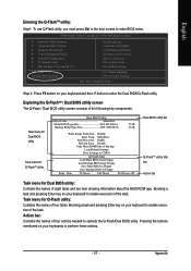
... F8: Dual BIOS/Q-Flash Select Language Load Fail-Safe Defaults Load Optimized Defaults Set Supervisor Password Set User Password Save & Exit Setup Exit Without Saving F3: Change Language F10: Save & Exit Setup Time, Date, Hard Disk Type... Blocking a task and pressing Enter key on your keyboard to enable execution of eight tasks and two item showing information about the BIOS ROM type. Pressing the buttons mentioned on your keyboards to enter the Dual BIOS/Q-Flash utility. Appendix Exploring the Q-FlashTM / Dual BIOS utility screen The Q-Flash / Dual BIOS utility screen consists of...
... F8: Dual BIOS/Q-Flash Select Language Load Fail-Safe Defaults Load Optimized Defaults Set Supervisor Password Set User Password Save & Exit Setup Exit Without Saving F3: Change Language F10: Save & Exit Setup Time, Date, Hard Disk Type... Blocking a task and pressing Enter key on your keyboard to enable execution of eight tasks and two item showing information about the BIOS ROM type. Pressing the buttons mentioned on your keyboards to enter the Dual BIOS/Q-Flash utility. Appendix Exploring the Q-FlashTM / Dual BIOS utility screen The Q-Flash / Dual BIOS utility screen consists of...
Manual
Page 60
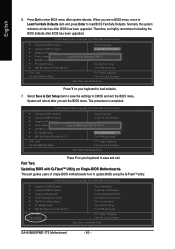
... BIOS Features Integrated Peripherals Power Management Setup PnP/PCI Configurations PC Health Status MB Intelligent Tweaker(M.I.T.) ESC: Quit F8: Q-Flash Top Performance Load Fail-Safe Defaults Load Optimized Defaults Set Supervisor Password Set User Password Save & Exit Setup Exit Without Saving F3: Change Language F10: Save & Exit Setup Time, Date, Hard Disk Type... GA-8VM800PMD-775 Motherboard - 60 - Normally the system redetects all devices after you are in BIOS menu, move to Load Fail-Safe Defaults item and press Enter to update BIOS using the Q-FlashTM utility...
... BIOS Features Integrated Peripherals Power Management Setup PnP/PCI Configurations PC Health Status MB Intelligent Tweaker(M.I.T.) ESC: Quit F8: Q-Flash Top Performance Load Fail-Safe Defaults Load Optimized Defaults Set Supervisor Password Set User Password Save & Exit Setup Exit Without Saving F3: Change Language F10: Save & Exit Setup Time, Date, Hard Disk Type... GA-8VM800PMD-775 Motherboard - 60 - Normally the system redetects all devices after you are in BIOS menu, move to Load Fail-Safe Defaults item and press Enter to update BIOS using the Q-FlashTM utility...
Manual
Page 66
...will see shall depend on your motherboard. CMOS Setup Utility-Copyright (C) 1984-2004 Award Software Integrated Peripherals OnChip IDE Channel 0 OnChip IDE Channel 1 OnChip Serial ATA SATA Mode AC97 Audio USB 1.1 Controller USB 2.0 Controller USB Keyboard Support USB Mouse Support Onboard H/W LAN OnBoard LAN Boot ROM Legacy USB storage detect Onboard Serial Port 1 Onboard Serial Port 2 Onboard Parallel Port Parallel Port Mode x EPP Mode Select [Enabled] [Enabled] [Enabled] [IDE] [Auto] [Enabled] [Enabled] [Disabled] [Disabled] [Enabled] [Disabled] [Enabled] [3F8/IRQ4] [2F8/IRQ3] [378/IRQ7...
...will see shall depend on your motherboard. CMOS Setup Utility-Copyright (C) 1984-2004 Award Software Integrated Peripherals OnChip IDE Channel 0 OnChip IDE Channel 1 OnChip Serial ATA SATA Mode AC97 Audio USB 1.1 Controller USB 2.0 Controller USB Keyboard Support USB Mouse Support Onboard H/W LAN OnBoard LAN Boot ROM Legacy USB storage detect Onboard Serial Port 1 Onboard Serial Port 2 Onboard Parallel Port Parallel Port Mode x EPP Mode Select [Enabled] [Enabled] [Enabled] [IDE] [Auto] [Enabled] [Enabled] [Disabled] [Disabled] [Enabled] [Disabled] [Enabled] [3F8/IRQ4] [2F8/IRQ3] [378/IRQ7...
Manual
Page 67
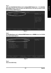
... Set First Boot Device under the Advanced BIOS Features menu. SCSI-0 : ST3120026AS 2. SCSI-1 : ST3120026AS 3. to install Microsoft Windows 2000/XP (Figure 2). CMOS Setup Utility-Copyright (C) 1984-2004 Award Software Hard Disk Boot Priority 1. CMOS Setup Utility-Copyright (C) 1984-2004 Award Software Advanced BIOS Features Hard Disk Boot Priority First Boot Device Second Boot Device Third Boot Device Password Check # CPU Hyper-Threading Limit CPUID Max. In the Hard Disk Boot Priority submenu, select the model of the SATA hard drive onto which you intent to 3 No-Execute Memory...
... Set First Boot Device under the Advanced BIOS Features menu. SCSI-0 : ST3120026AS 2. SCSI-1 : ST3120026AS 3. to install Microsoft Windows 2000/XP (Figure 2). CMOS Setup Utility-Copyright (C) 1984-2004 Award Software Hard Disk Boot Priority 1. CMOS Setup Utility-Copyright (C) 1984-2004 Award Software Advanced BIOS Features Hard Disk Boot Priority First Boot Device Second Boot Device Third Boot Device Password Check # CPU Hyper-Threading Limit CPUID Max. In the Hard Disk Boot Priority submenu, select the model of the SATA hard drive onto which you intent to 3 No-Execute Memory...
Manual
Page 73
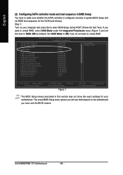
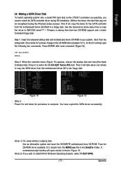
... installation. Appendix English (4) Making a SATA Driver Disk To install operating system onto a serial ATA hard disk on the VT8237 controllers successfully, you wish to install 64-bit Windows Operating System, select F) 8237-XP64. - 73 - Once at the A:\> prompt, change to exit when the procedure is complete. From the CD-ROM drive (example: D:\) double click the MENU.exe file in your system. Prepare a startup disk that in MS-DOS mode...
... installation. Appendix English (4) Making a SATA Driver Disk To install operating system onto a serial ATA hard disk on the VT8237 controllers successfully, you wish to install 64-bit Windows Operating System, select F) 8237-XP64. - 73 - Once at the A:\> prompt, change to exit when the procedure is complete. From the CD-ROM drive (example: D:\) double click the MENU.exe file in your system. Prepare a startup disk that in MS-DOS mode...

Manual
Page 74
... configured BIOS settings, you are ready to manually specify an adapter. Currently, Setup will be a few moments of Windows XP installation. Windows Setup Setup could not determine the type of one or more mass storage devices installed in your SATA hard drive with Windows, press ENTER. S=Specify Additional Device ENTER=Continue F3=Exit Figure 17 GA-8VM800PMD-775 Motherboard - 74 - The following mass storage devices(s) * To specify additional SCSI adapters, CD-ROM drives, or special disk controllers for which you have a device support disk...
... configured BIOS settings, you are ready to manually specify an adapter. Currently, Setup will be a few moments of Windows XP installation. Windows Setup Setup could not determine the type of one or more mass storage devices installed in your SATA hard drive with Windows, press ENTER. S=Specify Additional Device ENTER=Continue F3=Exit Figure 17 GA-8VM800PMD-775 Motherboard - 74 - The following mass storage devices(s) * To specify additional SCSI adapters, CD-ROM drives, or special disk controllers for which you have a device support disk...

Manual
Page 77
Click the icon to "Line Out." STEP 1: Connect the stereo speakers or earphone to select the function. Appendix STEP 3: On the AC97 Audio Configuration menu, click the Speaker Configuration tab and select the 2-channel mode for stereo speaker output check box. - 77 - English 4-1-5 2 / 4 / 6 Channel Audio Function Introduction 2 Channel Audio Setup We recommend that you 'll find a Sound Effect icon on the lower right hand taskbar. Line Out STEP 2: After installing the audio driver, you use speakers with amplifier to get the best sound effect if the stereo output is applied.
Click the icon to "Line Out." STEP 1: Connect the stereo speakers or earphone to select the function. Appendix STEP 3: On the AC97 Audio Configuration menu, click the Speaker Configuration tab and select the 2-channel mode for stereo speaker output check box. - 77 - English 4-1-5 2 / 4 / 6 Channel Audio Function Introduction 2 Channel Audio Setup We recommend that you 'll find a Sound Effect icon on the lower right hand taskbar. Line Out STEP 2: After installing the audio driver, you use speakers with amplifier to get the best sound effect if the stereo output is applied.
Manual
Page 83
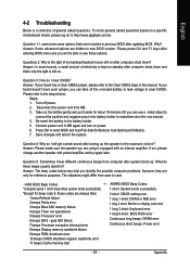
...read/write error 11 beeps Cache memory bad AWARD BIOS Beep Codes 1 short: System boots successfully 2 short: CMOS setting error 1 long 1 short: DRAM or M/B error 1 long 2 short: Monitor or display card error 1 long 3 short: Keyboard error 1 long 9 short: BIOS ROM error Continuous long beeps: DRAM error Continuous short beeps: Power error - 83 - Answer: Some advanced options are using is still on. Take out the battery gently and put it aside for ? Questions 2: Why is a collection of general asked questions based on a specific motherboard model, please log on to connect the...
...read/write error 11 beeps Cache memory bad AWARD BIOS Beep Codes 1 short: System boots successfully 2 short: CMOS setting error 1 long 1 short: DRAM or M/B error 1 long 2 short: Monitor or display card error 1 long 3 short: Keyboard error 1 long 9 short: BIOS ROM error Continuous long beeps: DRAM error Continuous short beeps: Power error - 83 - Answer: Some advanced options are using is still on. Take out the battery gently and put it aside for ? Questions 2: Why is a collection of general asked questions based on a specific motherboard model, please log on to connect the...


