
Manual
Page 4
...GA-8N775 Motherboard Layout 6 Block Diagram ...7 Chapter 1 Hardware Installation 9 1-1 Considerations Prior to Installation 9 1-2 Feature Summary 10 1-3 Installation of the CPU and Heatsink 12 1-3-1 Installation of the CPU 12 1-3-2 Installation of the Heatsink 13 1-4 Installation of Memory 14 1-5 Installation of Expansion Cards 16 1-6 I/O Back Panel Introduction 17 1-7 Connectors Introduction 18 Chapter 2 BIOS... Setup 29 The Main Menu (For example: BIOS Ver. : E5 30 2-1 Standard CMOS Features 32 2-2 Advanced BIOS Features 34 2-3 IntegratedPeripherals...
...GA-8N775 Motherboard Layout 6 Block Diagram ...7 Chapter 1 Hardware Installation 9 1-1 Considerations Prior to Installation 9 1-2 Feature Summary 10 1-3 Installation of the CPU and Heatsink 12 1-3-1 Installation of the CPU 12 1-3-2 Installation of the Heatsink 13 1-4 Installation of Memory 14 1-5 Installation of Expansion Cards 16 1-6 I/O Back Panel Introduction 17 1-7 Connectors Introduction 18 Chapter 2 BIOS... Setup 29 The Main Menu (For example: BIOS Ver. : E5 30 2-1 Standard CMOS Features 32 2-2 Advanced BIOS Features 34 2-3 IntegratedPeripherals...

Manual
Page 5
Chapter 3 Drivers Installation 49 3-1 Install Chipset Drivers 49 3-2 SoftwareApplication 50 3-3 Software Information 50 3-4 Hardware Information 51 3-5 Contact Us ...51 Chapter 4 Appendix 53 4-1 Unique Software Utilities 53 4-1-1 EasyTune 5 Introduction 54 4-1-2 Xpress Recovery2 Introduction 55 4-1-3 Flash BIOS Method Introduction 57 4-1-4 Configuring SATA Hard Drive(s 66 4-1-5 2- / 4- / 6- / 8- Channel Audio Function Introduction 80 4-2 Troubleshooting 84 - 5 -
Chapter 3 Drivers Installation 49 3-1 Install Chipset Drivers 49 3-2 SoftwareApplication 50 3-3 Software Information 50 3-4 Hardware Information 51 3-5 Contact Us ...51 Chapter 4 Appendix 53 4-1 Unique Software Utilities 53 4-1-1 EasyTune 5 Introduction 54 4-1-2 Xpress Recovery2 Introduction 55 4-1-3 Flash BIOS Method Introduction 57 4-1-4 Configuring SATA Hard Drive(s 66 4-1-5 2- / 4- / 6- / 8- Channel Audio Function Introduction 80 4-2 Troubleshooting 84 - 5 -

Manual
Page 6
GA-8N775 Motherboard Layout KB_MS COAXIAL SPDIF_O LGA775 ATX FDD COMA LPT LAN USB USB CD_IN SPDIF_IN AUDIO1 AUDIO2 CPU_FAN Marvell 88E1111/ 88E1115 ATX_12V F_AUDIO PCIE_1 CODEC PCIE_16 BIOS PCIE_2 PCIE_3 RF_ID nVIDIA® Crush 19 PCI1 PCI2 IT8712F CI F_USB1 F_USB2 F_USB3 GA-8N775 DDRII1 DDRII2 DDRII3 DDRII4 IDE2 IDE1 nVIDIA® MCP-04 SYS_FAN CLR_CMOS BATTERY SATAII2_3 SATAII0_1 PWR_LED F_PANEL - 6 -
GA-8N775 Motherboard Layout KB_MS COAXIAL SPDIF_O LGA775 ATX FDD COMA LPT LAN USB USB CD_IN SPDIF_IN AUDIO1 AUDIO2 CPU_FAN Marvell 88E1111/ 88E1115 ATX_12V F_AUDIO PCIE_1 CODEC PCIE_16 BIOS PCIE_2 PCIE_3 RF_ID nVIDIA® Crush 19 PCI1 PCI2 IT8712F CI F_USB1 F_USB2 F_USB3 GA-8N775 DDRII1 DDRII2 DDRII3 DDRII4 IDE2 IDE1 nVIDIA® MCP-04 SYS_FAN CLR_CMOS BATTERY SATAII2_3 SATAII0_1 PWR_LED F_PANEL - 6 -

Manual
Page 7
... (25MHz) HCLK+/- (133/200/266MHz) PCI-ECLK (100MHz) 3 PCI Express x 1 LAN RJ45 Marvell 88E1111/ 88E1115 PCI Bus nVIDIA® MCP-04 CODEC 33MHz 25MHz 48MHz BIOS ROMCLK33MHz 4 SATA 3Gb/s ATA33/66/100/133 IDE Channels Floppy LPC BUS IT8712F 24 MHz LPT Port COM Port 2 PCI PCICLK (33MHz) 10 USB Ports...
... (25MHz) HCLK+/- (133/200/266MHz) PCI-ECLK (100MHz) 3 PCI Express x 1 LAN RJ45 Marvell 88E1111/ 88E1115 PCI Bus nVIDIA® MCP-04 CODEC 33MHz 25MHz 48MHz BIOS ROMCLK33MHz 4 SATA 3Gb/s ATA33/66/100/133 IDE Channels Floppy LPC BUS IT8712F 24 MHz LPT Port COM Port 2 PCI PCICLK (33MHz) 10 USB Ports...
Manual
Page 11
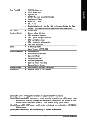
... fan failure warning Š CPU smart fan control BIOS Š 1 4Mbit flash ROM Š Use of licensed AWARD BIOS Additional Features Š Supports @BIOS Š Supports Download Center Š Supports Q-Flash... Š Supports EasyTune (Note 4) Š Supports Xpress Install Š Supports Xpress Recovery2 Š Supports Xpress Rescue Bundle Software Š Norton Internet Security (OEM version) Form Factor Š ATX form factor; 30.5cm x 24.4cm (Note 1) For further CPU support information, please go to GIGABYTE...
... fan failure warning Š CPU smart fan control BIOS Š 1 4Mbit flash ROM Š Use of licensed AWARD BIOS Additional Features Š Supports @BIOS Š Supports Download Center Š Supports Q-Flash... Š Supports EasyTune (Note 4) Š Supports Xpress Install Š Supports Xpress Recovery2 Š Supports Xpress Rescue Bundle Software Š Norton Internet Security (OEM version) Form Factor Š ATX form factor; 30.5cm x 24.4cm (Note 1) For further CPU support information, please go to GIGABYTE...
Manual
Page 12
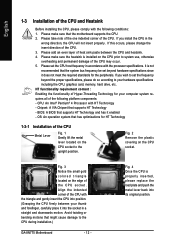
...system requires all of the CPU Metal Lever Fig. 1 Gently lift the metal lever located on the CPU prior to the CPU during installation.) GA-8N775 Motherboard - 12 - CPU: An Intel® Pentium® 4 Processor with the processor specifications. Fig. 2 Remove the plastic covering on the... required standards for HT Technology 1-3-1 Installation of the following conditions: 1. If you install the CPU in a straight and downwards motion. BIOS: A BIOS that the system bus frequency be set the CPU host frequency in accordance with HT Technology - If you wish to your thumb and ...
...system requires all of the CPU Metal Lever Fig. 1 Gently lift the metal lever located on the CPU prior to the CPU during installation.) GA-8N775 Motherboard - 12 - CPU: An Intel® Pentium® 4 Processor with the processor specifications. Fig. 2 Remove the plastic covering on the... required standards for HT Technology 1-3-1 Installation of the following conditions: 1. If you install the CPU in a straight and downwards motion. BIOS: A BIOS that the system bus frequency be set the CPU host frequency in accordance with HT Technology - If you wish to your thumb and ...

Manual
Page 14
... DDR II memory modules, whereby BIOS will automatically detect memory capacity and specifications. Reverse the installation steps when you are designed so that memory of Memory Before installing the memory modules, please comply with each slot. Insert the DIMM memory module vertically into the DIMM socket. GA-8N775 Motherboard - 14 - It is supported...
... DDR II memory modules, whereby BIOS will automatically detect memory capacity and specifications. Reverse the installation steps when you are designed so that memory of Memory Before installing the memory modules, please comply with each slot. Insert the DIMM memory module vertically into the DIMM socket. GA-8N775 Motherboard - 14 - It is supported...

Manual
Page 16
... you try to the onboard PCI Express x 16 slot and press firmly down on the computer, if necessary, setup BIOS utility of expansion card from the operating system. Install related driver from BIOS. 8. GA-8N775 Motherboard - 16 - Replace the screw to secure the slot bracket of the expansion card. 6. Make sure your VGA card...
... you try to the onboard PCI Express x 16 slot and press firmly down on the computer, if necessary, setup BIOS utility of expansion card from the operating system. Install related driver from BIOS. 8. GA-8N775 Motherboard - 16 - Replace the screw to secure the slot bracket of the expansion card. 6. Make sure your VGA card...

Manual
Page 21
Please refer to the BIOS setting for information on settings, please refer to the instructions located on one IDE cable, and the single IDE cable can provide up to two ...
Please refer to the BIOS setting for information on settings, please refer to the instructions located on one IDE cable, and the single IDE cable can provide up to two ...

Manual
Page 26
You can check the "Case Opened" status in BIOS Setup. Definition 1 Signal 1 2 GND GA-8N775 Motherboard - 26 - Pin No. To clear CMOS, temporarily short 1-2 pin. Default doesn't include the jumper to prevent from improper use of this header. 1 Open: Normal 1 Short: Clear CMOS 16) CI (Chassis Intrusion, Case Open) This 2-pin connector allows your system to its default values by this header. English 15) CLR_CMOS (Clear CMOS) You may clear the CMOS data to detect if the chassis cover is removed.
You can check the "Case Opened" status in BIOS Setup. Definition 1 Signal 1 2 GND GA-8N775 Motherboard - 26 - Pin No. To clear CMOS, temporarily short 1-2 pin. Default doesn't include the jumper to prevent from improper use of this header. 1 Open: Normal 1 Short: Clear CMOS 16) CI (Chassis Intrusion, Case Open) This 2-pin connector allows your system to its default values by this header. English 15) CLR_CMOS (Clear CMOS) You may clear the CMOS data to detect if the chassis cover is removed.

Manual
Page 29
... that describes the appropriate keys to the CMOS SRAM. Exit current page and return to a new BIOS, either Gigabyte's Q-Flash or @BIOS utility can enter the BIOS setup screen by pressing "Ctrl + F1". Quit and not save the current BIOS to a disk in the CMOS SRAM of the motherboard. Q-Flash allows the user to quickly...
... that describes the appropriate keys to the CMOS SRAM. Exit current page and return to a new BIOS, either Gigabyte's Q-Flash or @BIOS utility can enter the BIOS setup screen by pressing "Ctrl + F1". Quit and not save the current BIOS to a disk in the CMOS SRAM of the motherboard. Q-Flash allows the user to quickly...

Manual
Page 30
... arrow keys to select among the items and press to accept . Press to search the advanced option hidden. Please Load Optimized Defaults in this menu. GA-8N775 E5 . . . . :BIOS Setup/Q-Flash, : Xpress Recovery2, For Boot Menu 11/16/2005-C19-MCP04-6A61EG0FC-00 For Boot Menu Use < > or < > to select ... Save & Exit Setup Exit Without Saving ESC: Quit F8: Q-Flash KLJI: Select Item F10: Save & Exit Setup Time, Date, Hard Disk Type... GA-8N775 Motherboard - 30 - Boot Menu == Select a Boot First device == Floppy LS120 Hard Disk CDROM ZIP USB-FDD USB-ZIP USB-CDROM USB-HDD LAN ...
... arrow keys to select among the items and press to accept . Press to search the advanced option hidden. Please Load Optimized Defaults in this menu. GA-8N775 E5 . . . . :BIOS Setup/Q-Flash, : Xpress Recovery2, For Boot Menu 11/16/2005-C19-MCP04-6A61EG0FC-00 For Boot Menu Use < > or < > to select ... Save & Exit Setup Exit Without Saving ESC: Quit F8: Q-Flash KLJI: Select Item F10: Save & Exit Setup Time, Date, Hard Disk Type... GA-8N775 Motherboard - 30 - Boot Menu == Select a Boot First device == Floppy LS120 Hard Disk CDROM ZIP USB-FDD USB-ZIP USB-CDROM USB-HDD LAN ...

Manual
Page 31
BIOS Setup English „ Standard CMOS Features This setup page includes all the items in best performance configuration. „ Set Supervisor Password Change, set , or disable ... in safe configuration. „ Load Optimized Defaults Optimized Defaults indicates the value of the system parameters which the system would be in standard compatible BIOS. „ Advanced BIOS Features This setup page includes all the items of Award special enhanced features. „ Integrated Peripherals This setup page includes all onboard peripherals. „...
BIOS Setup English „ Standard CMOS Features This setup page includes all the items in best performance configuration. „ Set Supervisor Password Change, set , or disable ... in safe configuration. „ Load Optimized Defaults Optimized Defaults indicates the value of the system parameters which the system would be in standard compatible BIOS. „ Advanced BIOS Features This setup page includes all the items of Award special enhanced features. „ Integrated Peripherals This setup page includes all onboard peripherals. „...
Manual
Page 32
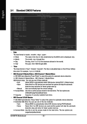
.../Slave IDE HDD Auto-Detection Press "Enter" to select this option for automatic device detection. You can use one of three methods: • Auto Allows BIOS to automatically detect IDE devices during POST(default) • None Select this to 31 (or maximum allowed in . Day The day, from 1 to 31 (or... step and allow for the hard drive. Jan. IDE Channel 0 Master/Slave ; Access Mode Use this if no IDE devices are : Large/Auto(default:Auto) GA-8N775 Motherboard - 32 - Time The times format in the month) 1999 to Sat.
.../Slave IDE HDD Auto-Detection Press "Enter" to select this option for automatic device detection. You can use one of three methods: • Auto Allows BIOS to automatically detect IDE devices during POST(default) • None Select this to 31 (or maximum allowed in . Day The day, from 1 to 31 (or... step and allow for the hard drive. Jan. IDE Channel 0 Master/Slave ; Access Mode Use this if no IDE devices are : Large/Auto(default:Auto) GA-8N775 Motherboard - 32 - Time The times format in the month) 1999 to Sat.
Manual
Page 33
... The category is display-only which is determined by POST (Power On Self Test) of currently installed hard drive. Extended Memory The BIOS determines how much extended memory is detected during the POST. Cylinder Number of cylinders Head Number of heads Precomp Write precomp Landing Zone Landing... Support (for a keyboard or disk error; The value of floppy disk drive A or drive B that used. - 33 - This is 3 mode Floppy Drive. BIOS Setup All, But Keyboard The system boot will stop for all other errors. it will not stop for a keyboard error; Base Memory The POST of...
... The category is display-only which is determined by POST (Power On Self Test) of currently installed hard drive. Extended Memory The BIOS determines how much extended memory is detected during the POST. Cylinder Number of cylinders Head Number of heads Precomp Write precomp Landing Zone Landing... Support (for a keyboard or disk error; The value of floppy disk drive A or drive B that used. - 33 - This is 3 mode Floppy Drive. BIOS Setup All, But Keyboard The system boot will stop for all other errors. it will not stop for a keyboard error; Base Memory The POST of...

Manual
Page 34
...CDROM Select your boot device priority by USB-CDROM. Disabled Disable this menu. Note that BIOS can not tell from 720K, 1.2M or 1.44M drive type as they are all 80 tracks. GA-8N775 Motherboard - 34 - to exit this function. First / Second / Third Boot Device... Floppy Select your boot device priority by LAN. Enabled BIOS searches for onboard(or add-on cards) SCSI, RAID, etc. Disabled BIOS will determine the floppy disk ...
...CDROM Select your boot device priority by USB-CDROM. Disabled Disable this menu. Note that BIOS can not tell from 720K, 1.2M or 1.44M drive type as they are all 80 tracks. GA-8N775 Motherboard - 34 - to exit this function. First / Second / Third Boot Device... Floppy Select your boot device priority by LAN. Enabled BIOS searches for onboard(or add-on cards) SCSI, RAID, etc. Disabled BIOS will determine the floppy disk ...
Manual
Page 35
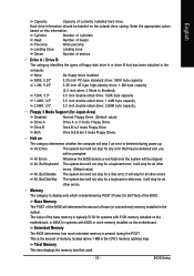
... at the prompt. CPU Hyper-Threading This option appears only when the processor you install a PCI card and a PCI Express VGA card on the motherboard. BIOS Setup Disabled Disable CPUID Limit for operating system with multi processors mode supported. (Default value) Disabled Disable CPU Hyper Threading. Set Init Display First to...
... at the prompt. CPU Hyper-Threading This option appears only when the processor you install a PCI card and a PCI Express VGA card on the motherboard. BIOS Setup Disabled Disable CPUID Limit for operating system with multi processors mode supported. (Default value) Disabled Disable CPU Hyper Threading. Set Init Display First to...

Manual
Page 37
... value) ATA66/100/133 Set IDE2 Conductor Cable to ATA33 (Please make sure your IDE device and cable are compatible with ATA33). BIOS Setup Disabled Disable this function. (Default value) SATAII 2 Secondary RAID Enabled Enable SATAII 2 2nd SATA RAID function. ATA33 Set IDE1... Disable this function. (Default value) SATAII 1 Secondary RAID Enabled Disabled Enable SATAII 1 2nd SATA RAID function. IDE1 Conductor Cable Auto BIOS autodetects IDE1 conductor cable. (Default value) ATA66/100/133 Set IDE1 Conductor Cable to ATA33 (Please make sure your IDE device and ...
... value) ATA66/100/133 Set IDE2 Conductor Cable to ATA33 (Please make sure your IDE device and cable are compatible with ATA33). BIOS Setup Disabled Disable this function. (Default value) SATAII 2 Secondary RAID Enabled Enable SATAII 2 2nd SATA RAID function. ATA33 Set IDE1... Disable this function. (Default value) SATAII 1 Secondary RAID Enabled Disabled Enable SATAII 1 2nd SATA RAID function. IDE1 Conductor Cable Auto BIOS autodetects IDE1 conductor cable. (Default value) ATA66/100/133 Set IDE1 Conductor Cable to ATA33 (Please make sure your IDE device and ...

Manual
Page 38
... Enable onboard LPT port and address is 2F8. ECP ECP+EPP Using Parallel port as ECP & EPP mode. Using Parallel port as Extended Capabilities Port. GA-8N775 Motherboard - 38 - USB Keyboard Support Enabled Disabled Enable USB keyboard support. Parallel Port Mode SPP Using Parallel port as Standard Parallel Port. (Default value) EPP... invoke the boot ROM of the onboard LAN chip. Enabled Enable this function. Disabled Disable this function. (Default value) Onboard Serial Port 1 Auto 3F8/IRQ4 BIOS will automatically setup the port 1 address.
... Enable onboard LPT port and address is 2F8. ECP ECP+EPP Using Parallel port as ECP & EPP mode. Using Parallel port as Extended Capabilities Port. GA-8N775 Motherboard - 38 - USB Keyboard Support Enabled Disabled Enable USB keyboard support. Parallel Port Mode SPP Using Parallel port as Standard Parallel Port. (Default value) EPP... invoke the boot ROM of the onboard LAN chip. Enabled Enable this function. Disabled Disable this function. (Default value) Onboard Serial Port 1 Auto 3F8/IRQ4 BIOS will automatically setup the port 1 address.

Manual
Page 39
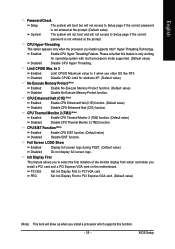
... from Suspend Disabled Enabled Disable this function. PME Event Wake Up This feature requires an ATX power supply that provides at least 1A on system. BIOS Setup
... from Suspend Disabled Enabled Disable this function. PME Event Wake Up This feature requires an ATX power supply that provides at least 1A on system. BIOS Setup


