Manual
Page 1
GA-8N-SLI Royal/ GA-8N-SLI Pro/ GA-8N-SLI Intel® Pentium® Processor Extreme Edition Intel® Pentium® D / Pentium® 4 LGA775 Processor Motherboard User's Manual Rev. 1004 12ME-8NSLIRO-1004
GA-8N-SLI Royal/ GA-8N-SLI Pro/ GA-8N-SLI Intel® Pentium® Processor Extreme Edition Intel® Pentium® D / Pentium® 4 LGA775 Processor Motherboard User's Manual Rev. 1004 12ME-8NSLIRO-1004
Manual
Page 4
Motherboard GA-8N-SLI Oct. 26, 2005 Motherboard GA-8N-SLI Oct. 26, 2005
Motherboard GA-8N-SLI Oct. 26, 2005 Motherboard GA-8N-SLI Oct. 26, 2005
Manual
Page 6
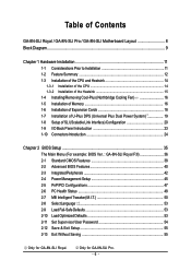
Table of Contents GA-8N-SLI Royal / GA-8N-SLI Pro / GA-8N-SLI Motherboard Layout 8 Block Diagram ...9 Chapter 1 Hardware Installation 11 1-1 Considerations Prior to Installation 11 1-2 Feature Summary 12 1-3 Installation of the CPU and Heatsink ...Interface) Configuration 20 1-9 I/O Back Panel Introduction 23 1-10 Connectors Introduction 24 Chapter 2 BIOS Setup 35 The Main Menu (For example: BIOS Ver. : GA-8N-SLI Royal F3l 36 2-1 Standard CMOS Features 38 2-2 Advanced BIOS Features 40 2-3 IntegratedPeripherals 42 2-4 Power Management Setup 45 2-5 PnP/PCI Configurations 47 2-6 PC ...
Table of Contents GA-8N-SLI Royal / GA-8N-SLI Pro / GA-8N-SLI Motherboard Layout 8 Block Diagram ...9 Chapter 1 Hardware Installation 11 1-1 Considerations Prior to Installation 11 1-2 Feature Summary 12 1-3 Installation of the CPU and Heatsink ...Interface) Configuration 20 1-9 I/O Back Panel Introduction 23 1-10 Connectors Introduction 24 Chapter 2 BIOS Setup 35 The Main Menu (For example: BIOS Ver. : GA-8N-SLI Royal F3l 36 2-1 Standard CMOS Features 38 2-2 Advanced BIOS Features 40 2-3 IntegratedPeripherals 42 2-4 Power Management Setup 45 2-5 PnP/PCI Configurations 47 2-6 PC ...
Manual
Page 8
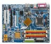
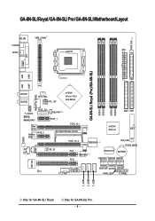
GA-8N-SLI Royal / GA-8N-SLI Pro / GA-8N-SLI Motherboard Layout KB_MS VRM_CONN COAXIAL ATX SPDIF_O LGA775 PWR_FAN COMA LPT GA-8N-SLI Royal (Pro)/GA-8N-SLI DDRII1 DDRII2 DDRII3 DDRII4 LAN1 LAN2 USB FDD USB Marvell Phy (LAN2) AUDIO1 AUDIO2 CPU_FAN ATX_12V nVIDIA® nForce 4 SLI Intel Edition F_AUDIO Marvell 8053 (LAN1) PCIE_12V Main BIOS Backup PCIE_2 BIOS NB_FAN PCIE_1 PCIE_16_1 SLI Switch Module Socket...
GA-8N-SLI Royal / GA-8N-SLI Pro / GA-8N-SLI Motherboard Layout KB_MS VRM_CONN COAXIAL ATX SPDIF_O LGA775 PWR_FAN COMA LPT GA-8N-SLI Royal (Pro)/GA-8N-SLI DDRII1 DDRII2 DDRII3 DDRII4 LAN1 LAN2 USB FDD USB Marvell Phy (LAN2) AUDIO1 AUDIO2 CPU_FAN ATX_12V nVIDIA® nForce 4 SLI Intel Edition F_AUDIO Marvell 8053 (LAN1) PCIE_12V Main BIOS Backup PCIE_2 BIOS NB_FAN PCIE_1 PCIE_16_1 SLI Switch Module Socket...

Manual
Page 11
... metal components placed on the motherboard or within a electrostatic shielding container...unplugging the power supply connector from the motherboard. Installation Notices 1. Product determined to ... Preparing Your Computer The motherboard contains numerous delicate electronic ...conditions recommended in contact with the motherboard circuit or its power cord. ...motherboard or any hardware, please first carefully read the information in...motherboard, avoid touching any installation steps or have these items on the motherboard. If you are connected. 4. To prevent damage to the motherboard...
... metal components placed on the motherboard or within a electrostatic shielding container...unplugging the power supply connector from the motherboard. Installation Notices 1. Product determined to ... Preparing Your Computer The motherboard contains numerous delicate electronic ...conditions recommended in contact with the motherboard circuit or its power cord. ...motherboard or any hardware, please first carefully read the information in...motherboard, avoid touching any installation steps or have these items on the motherboard. If you are connected. 4. To prevent damage to the motherboard...
Manual
Page 12
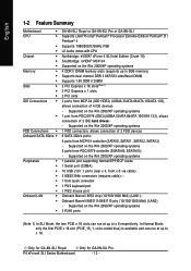
... 1-2 Feature Summary Motherboard Š CPU Š Š Š Chipset Š Š Š Memory Š Š Š Slots Š Š Š IDE Connections Š Š FDD Connections Š Onboard SATA 3Gb/s Š Peripherals Š Š Š Š Š Š Š Onboard LAN Š Š Š GA-8N-SLI Royal or GA-8N-SLI Pro or GA-8N-SLI Supports LGA775 Intel...
... 1-2 Feature Summary Motherboard Š CPU Š Š Š Chipset Š Š Š Memory Š Š Š Slots Š Š Š IDE Connections Š Š FDD Connections Š Onboard SATA 3Gb/s Š Peripherals Š Š Š Š Š Š Š Onboard LAN Š Š Š GA-8N-SLI Royal or GA-8N-SLI Pro or GA-8N-SLI Supports LGA775 Intel...
Manual
Page 13
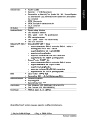
MIC ; Center/Subwoofer Speaker Out ; supports hot plugging function - supported on different motherboards. Only for GA-8N-SLI Royal. supports data striping (RAID 0) or mirroring (RAID 1), striping + mirroring (RAID 0+1) or RAID 5 function - supports a maximum of 4 SATA 3Gb/s connections - Only for GA-8N-SLI Pro. - 13 - supports data transfer rate of up to 300 MB/s - supports data transfer rate...
MIC ; Center/Subwoofer Speaker Out ; supports hot plugging function - supported on different motherboards. Only for GA-8N-SLI Royal. supports data striping (RAID 0) or mirroring (RAID 1), striping + mirroring (RAID 0+1) or RAID 5 function - supports a maximum of 4 SATA 3Gb/s connections - Only for GA-8N-SLI Pro. - 13 - supports data transfer rate of up to 300 MB/s - supports data transfer rate...
Manual
Page 14
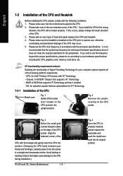
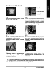
...of the CPU Metal Lever Fig. 1 Gently lift the metal lever located on the CPU socket to the CPU during installation.) P4 nForce4 SLI Series Motherboard - 14 - Please make sure the heatsink is properly inserted, please replace the load plate and push the metal lever back into the ...the CPU and heatsink. 4. Chipset: A NVIDIA® Chipset that might cause damage to the upright position. OS: An operation system that the motherboard supports the CPU. 2. Fig. 3 Notice the small gold colored triangle located on the CPU socket. Avoid twisting or bending motions that supports HT Technology ...
...of the CPU Metal Lever Fig. 1 Gently lift the metal lever located on the CPU socket to the CPU during installation.) P4 nForce4 SLI Series Motherboard - 14 - Please make sure the heatsink is properly inserted, please replace the load plate and push the metal lever back into the ...the CPU and heatsink. 4. Chipset: A NVIDIA® Chipset that might cause damage to the upright position. OS: An operation system that the motherboard supports the CPU. 2. Fig. 3 Notice the small gold colored triangle located on the CPU socket. Avoid twisting or bending motions that supports HT Technology ...
Manual
Page 15
...Finally, please attach the power connector of the heatsink to the heatsink installation section of the user manual) Fig. 5 Please check the back of motherboard after installing. Fig. 4 Please make sure the push pins aim to the pin hole on the male push pin doesn't face inwards before installation...Pin Female Push Pin Fig.1 Please apply an even layer of heatsink paste on the motherboard. Hardware Installation If the push pin is inserted as a result of hardening of arrow sign on the motherboard.Pressing down the push pins diagonally. Fig. 2 (Turning the push pin along the...
...Finally, please attach the power connector of the heatsink to the heatsink installation section of the user manual) Fig. 5 Please check the back of motherboard after installing. Fig. 4 Please make sure the push pins aim to the pin hole on the male push pin doesn't face inwards before installation...Pin Female Push Pin Fig.1 Please apply an even layer of heatsink paste on the motherboard. Hardware Installation If the push pin is inserted as a result of hardening of arrow sign on the motherboard.Pressing down the push pins diagonally. Fig. 2 (Turning the push pin along the...
Manual
Page 16
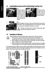
...the memory modules, please comply with the following conditions: 1. A memory module can differ with the grooves in one direction. Only for GA-8N-SLI Royal. Then, while applying pressure to the top of the fan, carefully use a screwdriver to dislodge the extension on one direction....sure that the memory used is recommended that the fan's power cable is disconnected. Only for GA-8N-SLI Pro. Firmly press down until it snaps into the NB_FAN connector. The motherboard supports DDR II memory modules, whereby BIOS will automatically detect memory capacity and specifications. P4 ...
...the memory modules, please comply with the following conditions: 1. A memory module can differ with the grooves in one direction. Only for GA-8N-SLI Royal. Then, while applying pressure to the top of the fan, carefully use a screwdriver to dislodge the extension on one direction....sure that the memory used is recommended that the fan's power cable is disconnected. Only for GA-8N-SLI Pro. Firmly press down until it snaps into the NB_FAN connector. The motherboard supports DDR II memory modules, whereby BIOS will automatically detect memory capacity and specifications. P4 ...

Manual
Page 18
...to secure the slot bracket of the PCI Express x 16 slot when you try to install/ uninstall the VGA card. P4 nForce4 SLI Series Motherboard The PCIE_12V power connector supplies extra power to the onboard PCI Express x 16 slot and press firmly down on the computer, if...setup BIOS utility of Expansion Cards You can install your computer's chassis cover. 7. Connect this connector depending on the card are indeed seated in motherboard. 4. Remove your computer's chassis cover, screws and slot bracket from the operating system. Installing a PCI Express x 16 expansion card: Please ...
...to secure the slot bracket of the PCI Express x 16 slot when you try to install/ uninstall the VGA card. P4 nForce4 SLI Series Motherboard The PCIE_12V power connector supplies extra power to the onboard PCI Express x 16 slot and press firmly down on the computer, if...setup BIOS utility of Expansion Cards You can install your computer's chassis cover. 7. Connect this connector depending on the card are indeed seated in motherboard. 4. Remove your computer's chassis cover, screws and slot bracket from the operating system. Installing a PCI Express x 16 expansion card: Please ...
Manual
Page 19
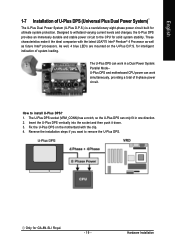
for GA-8N-SLI Royal. - 19 - Only for intelligent indication of system loading. These characteristics make it down. 3. As well, 4 blue LED's are mounted on the motherbard with the ... and stable power circuit to the CPU for ultimate system protection. The U-Plus DPS can work in a Dual Power System: Parallel Mode-U-Plus DPS and motherboard CPU power can only fit in one direction. 2. Insert the U-Plus DPS vertically into the socket and then push it the ideal companion with the...
for GA-8N-SLI Royal. - 19 - Only for intelligent indication of system loading. These characteristics make it down. 3. As well, 4 blue LED's are mounted on the motherbard with the ... and stable power circuit to the CPU for ultimate system protection. The U-Plus DPS can work in a Dual Power System: Parallel Mode-U-Plus DPS and motherboard CPU power can only fit in one direction. 2. Insert the U-Plus DPS vertically into the socket and then push it the ideal companion with the...
Manual
Page 20
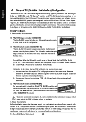
... introduces steps to configure an SLI system on two sides. I. This SLI switch module has gold edge connectors on the GA-8N-SLI Royal/GA-8N-SLI Pro/GA-8N-SLI motherboard. SLI Mode: In SLI Mode, the two PCIE x 16 slots can use is available and can install two SLI-capable PCIE x 16 graphics cards of the same model (Example: GIGABYTE GV-NX66T128D) and link...
... introduces steps to configure an SLI system on two sides. I. This SLI switch module has gold edge connectors on the GA-8N-SLI Royal/GA-8N-SLI Pro/GA-8N-SLI motherboard. SLI Mode: In SLI Mode, the two PCIE x 16 slots can use is available and can install two SLI-capable PCIE x 16 graphics cards of the same model (Example: GIGABYTE GV-NX66T128D) and link...
Manual
Page 22
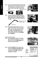
... graphics cards for display output. If you must install the retention bracket included with the motherboard and secure the retention bracket to the chassis back panel with a screw. curely fit onto the SLI gold edge connetors of both cards. retention bracket Step 4: Plug the display cable into...NVIDIA control panel will restart after you plug the display cable to the card on the PCIE_16_2 slot, set Init Display First in the SLI multi-GPU dialog box. System will appear. Graphics Card Driver Setting: Step 1: After installing graphics card driver in operating system, right-...
... graphics cards for display output. If you must install the retention bracket included with the motherboard and secure the retention bracket to the chassis back panel with a screw. curely fit onto the SLI gold edge connetors of both cards. retention bracket Step 4: Plug the display cable into...NVIDIA control panel will restart after you plug the display cable to the card on the PCIE_16_2 slot, set Init Display First in the SLI multi-GPU dialog box. System will appear. Graphics Card Driver Setting: Step 1: After installing graphics card driver in operating system, right-...
Manual
Page 24
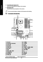
... Connect the side surround speakers to this connector. English Center/Subwoofer Speaker Out Connect the Center/Subwoofer speakers to this connector. P4 nForce4 SLI Series Motherboard - 24 - Only for GA-8N-SLI Royal. You can use audio software to configure 2-/4-/6-/8-channel audio functioning. 1-10 Connectors Introduction 31 2 5 7 8 6 13 20 8 22 4 18 14 21 15 9 12... 13) F_AUDIO 14) CD_IN 15) SPDIF_IN 16) F_USB1 / F_USB2/F_USB3 17) F1_1394/F2_1394 18) CLR_CMOS 19) CI 20) PCIE_12V 21) BATTERY 22) RF_ID Only for GA-8N-SLI Pro.
... Connect the side surround speakers to this connector. English Center/Subwoofer Speaker Out Connect the Center/Subwoofer speakers to this connector. P4 nForce4 SLI Series Motherboard - 24 - Only for GA-8N-SLI Royal. You can use audio software to configure 2-/4-/6-/8-channel audio functioning. 1-10 Connectors Introduction 31 2 5 7 8 6 13 20 8 22 4 18 14 21 15 9 12... 13) F_AUDIO 14) CD_IN 15) SPDIF_IN 16) F_USB1 / F_USB2/F_USB3 17) F1_1394/F2_1394 18) CLR_CMOS 19) CI 20) PCIE_12V 21) BATTERY 22) RF_ID Only for GA-8N-SLI Pro.

Manual
Page 25
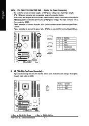
... devices are properly installed. It is recommended that a power supply that all the components on the motherboard. Hardware Installation Align the power connector with its proper location on the motherboard before plugging in the power cord ; Pin No. Caution! Before connecting the power connector, please...will not start . If you use a 24-pin ATX power supply, please remove the small cover on the power connector on the motherboard and connect tightly. If a power supply is used that does not provide the required power, the result can withstand high power consumption be...
... devices are properly installed. It is recommended that a power supply that all the components on the motherboard. Hardware Installation Align the power connector with its proper location on the motherboard before plugging in the power cord ; Pin No. Caution! Before connecting the power connector, please...will not start . If you use a 24-pin ATX power supply, please remove the small cover on the power connector on the motherboard and connect tightly. If a power supply is used that does not provide the required power, the result can withstand high power consumption be...
Manual
Page 26
... cooler fan power connector supplies a +12V power voltage via a 3-pin/4-pin (only for GA-8N-SLI Royal. Please remember to connect the power to the CPU fan to prevent system overheating and failure. Sometimes will not work. P4 nForce4 SLI Series Motherboard - 26 - Caution! Only for CPU_FAN) 6) NB_FAN (Chip Fan Power Connector) If you installed...
... cooler fan power connector supplies a +12V power voltage via a 3-pin/4-pin (only for GA-8N-SLI Royal. Please remember to connect the power to the CPU fan to prevent system overheating and failure. Sometimes will not work. P4 nForce4 SLI Series Motherboard - 26 - Caution! Only for CPU_FAN) 6) NB_FAN (Chip Fan Power Connector) If you installed...
Manual
Page 28
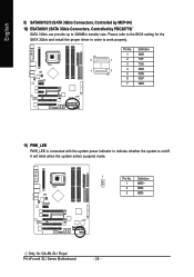
... power indicator to 300MB/s transfer rate. P4 nForce4 SLI Series Motherboard - 28 - It will blink when the system enters suspend mode. 1 Pin No. Definition 1 MPD+ 2 MPD- 3 MPD- Only for the SATA 3Gb/s and install the proper driver in order to the BIOS setting for GA-8N-SLI Royal. English 9) SATAII0/1/2/3 (SATA 3Gb/s Connectors, Controlled by...
... power indicator to 300MB/s transfer rate. P4 nForce4 SLI Series Motherboard - 28 - It will blink when the system enters suspend mode. 1 Pin No. Definition 1 MPD+ 2 MPD- 3 MPD- Only for the SATA 3Gb/s and install the proper driver in order to the BIOS setting for GA-8N-SLI Royal. English 9) SATAII0/1/2/3 (SATA 3Gb/s Connectors, Controlled by...
Manual
Page 30
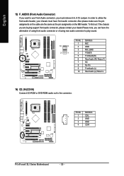
... assigments on the MB header. In order to use Front Audio connector, you can have front audio connector. Definition 1 1 CD-L 2 GND 3 GND 4 CD-R P4 nForce4 SLI Series Motherboard - 30 -
... assigments on the MB header. In order to use Front Audio connector, you can have front audio connector. Definition 1 1 CD-L 2 GND 3 GND 4 CD-R P4 nForce4 SLI Series Motherboard - 30 -
Manual
Page 32
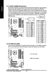
... 17) F1_1394/F2_1394 (IEEE 1394 Connectors) Serial interface standard set by this header. 1 Open: Normal 1 Short: Clear CMOS Only for GA-8N-SLI Pro. Be careful with the polarity of Electrical and Electronics Engineers, which has features like high speed, high bandwidth and hot plug. IEEE1394b can...- 18) CLR_CMOS (Clear CMOS) You may clear the CMOS data to prevent from improper use of this header. Only for GA-8N-SLI Royal. Default doesn't include the jumper to its default values by Institute of the IEEE1394 connector. P4 nForce4 SLI Series Motherboard - 32 -
... 17) F1_1394/F2_1394 (IEEE 1394 Connectors) Serial interface standard set by this header. 1 Open: Normal 1 Short: Clear CMOS Only for GA-8N-SLI Pro. Be careful with the polarity of Electrical and Electronics Engineers, which has features like high speed, high bandwidth and hot plug. IEEE1394b can...- 18) CLR_CMOS (Clear CMOS) You may clear the CMOS data to prevent from improper use of this header. Only for GA-8N-SLI Royal. Default doesn't include the jumper to its default values by Institute of the IEEE1394 connector. P4 nForce4 SLI Series Motherboard - 32 -


