Manual
Page 8
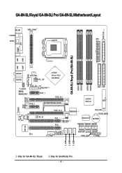
... / GA-8N-SLI Pro / GA-8N-SLI Motherboard Layout KB_MS VRM_CONN COAXIAL ATX SPDIF_O LGA775 PWR_FAN COMA LPT GA-8N-SLI Royal (Pro)/GA-8N-SLI DDRII1 DDRII2 DDRII3 DDRII4 LAN1 LAN2 USB FDD USB Marvell Phy (LAN2) AUDIO1 AUDIO2 CPU_FAN ATX_12V nVIDIA® nForce 4 SLI Intel Edition F_AUDIO Marvell 8053 (LAN1) PCIE_12V Main BIOS Backup PCIE_2 BIOS NB_FAN PCIE_1 PCIE_16_1 SLI Switch Module Socket...
... / GA-8N-SLI Pro / GA-8N-SLI Motherboard Layout KB_MS VRM_CONN COAXIAL ATX SPDIF_O LGA775 PWR_FAN COMA LPT GA-8N-SLI Royal (Pro)/GA-8N-SLI DDRII1 DDRII2 DDRII3 DDRII4 LAN1 LAN2 USB FDD USB Marvell Phy (LAN2) AUDIO1 AUDIO2 CPU_FAN ATX_12V nVIDIA® nForce 4 SLI Intel Edition F_AUDIO Marvell 8053 (LAN1) PCIE_12V Main BIOS Backup PCIE_2 BIOS NB_FAN PCIE_1 PCIE_16_1 SLI Switch Module Socket...
Manual
Page 14
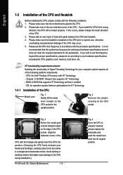
...If this occurs, please change the insert direction of the following conditions: 1. Fig. 2 Remove the plastic covering on the CPU socket to the CPU during installation.) P4 nForce4 SLI Series Motherboard - 14 - Fig. 3 Notice the small gold colored triangle located on the edge of the CPU Metal Lever ...Fig. 1 Gently lift the metal lever located on the CPU socket. If you install the CPU in a straight and downwards...
...If this occurs, please change the insert direction of the following conditions: 1. Fig. 2 Remove the plastic covering on the CPU socket to the CPU during installation.) P4 nForce4 SLI Series Motherboard - 14 - Fig. 3 Notice the small gold colored triangle located on the edge of the CPU Metal Lever ...Fig. 1 Gently lift the metal lever located on the CPU socket. If you install the CPU in a straight and downwards...
Manual
Page 17
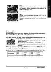
... push it is for Dual Channel Technology to use memory modules of Memory Bus will double. Dual Channel DDR II GA-8N-SLI Royal/GA-8N-SLI Pro/GA-8N-SLI supports the Dual Channel Technology. After operating the Dual Channel Technology, the bandwidth of identical brand, size, chips,... and speed. To enable Dual Channel mode with 2 or 4 memory modules, it down. Insert the DIMM memory module vertically into the DIMMs of the DIMM sockets...
... push it is for Dual Channel Technology to use memory modules of Memory Bus will double. Dual Channel DDR II GA-8N-SLI Royal/GA-8N-SLI Pro/GA-8N-SLI supports the Dual Channel Technology. After operating the Dual Channel Technology, the bandwidth of identical brand, size, chips,... and speed. To enable Dual Channel mode with 2 or 4 memory modules, it down. Insert the DIMM memory module vertically into the DIMMs of the DIMM sockets...
Manual
Page 19
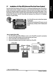
...varying current levels and changes, the U-Plus DPS provides an immensely durable and stable power circuit to install U-Plus DPS? 1. How to the CPU for GA-8N-SLI Royal. - 19 - The U-Plus DPS can work in a Dual Power System: Parallel Mode-U-Plus DPS and motherboard CPU power can only fit in ...one direction. 2. Reverse the installation steps if you want to remove the U-Plus DPS. Insert the U-Plus DPS vertically into the socket and then push it the ideal companion with the clip. 4. As well, 4 blue LED's are mounted on the motherbard with the latest LGA775 Intel...
...varying current levels and changes, the U-Plus DPS provides an immensely durable and stable power circuit to install U-Plus DPS? 1. How to the CPU for GA-8N-SLI Royal. - 19 - The U-Plus DPS can work in a Dual Power System: Parallel Mode-U-Plus DPS and motherboard CPU power can only fit in ...one direction. 2. Reverse the installation steps if you want to remove the U-Plus DPS. Insert the U-Plus DPS vertically into the socket and then push it the ideal companion with the clip. 4. As well, 4 blue LED's are mounted on the motherbard with the latest LGA775 Intel...
Manual
Page 20
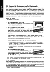
...overall system configurations. One is SLI Mode and the other components in the SLI switch module socket by factory default. P4 nForce4 SLI Series Motherboard - 20 - English 1-8 Setup of SLI (Scalable Link Interface) Configuration The nVIDIA® nForce 4 SLI Intel Edition chipset offers blistering ...available in two ways: 1. This SLI switch module has gold edge connectors on the GA-8N-SLI Royal/GA-8N-SLI Pro/GA-8N-SLI motherboard. GC-SLICON GC-SLISW-C19 Normal Mode: When the SLI switch module is set up an SLI configuration. … The SLI switch module (GC-SLISW-C19) The...
...overall system configurations. One is SLI Mode and the other components in the SLI switch module socket by factory default. P4 nForce4 SLI Series Motherboard - 20 - English 1-8 Setup of SLI (Scalable Link Interface) Configuration The nVIDIA® nForce 4 SLI Intel Edition chipset offers blistering ...available in two ways: 1. This SLI switch module has gold edge connectors on the GA-8N-SLI Royal/GA-8N-SLI Pro/GA-8N-SLI motherboard. GC-SLICON GC-SLISW-C19 Normal Mode: When the SLI switch module is set up an SLI configuration. … The SLI switch module (GC-SLISW-C19) The...
Manual
Page 21
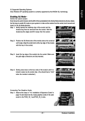
...insert it in "1-6 Installation of Expansion Cards" on page 16 and install two SLI-ready graphics cards of the same model to enable SLI mode on the two ends of the socket and the module may then be removed from the socket. Step 1: Gently spread the retaining clips of the module until it away... gold edge connectors are fully inserted. Align the small notch at a 25o angle. Hardware Installation Step 2: Position the SLI Mode side of the module above the socket at the top edge of the module into the socket. Hold the module by the edges and lift it is locked in place by the NVIDIA...
...insert it in "1-6 Installation of Expansion Cards" on page 16 and install two SLI-ready graphics cards of the same model to enable SLI mode on the two ends of the socket and the module may then be removed from the socket. Step 1: Gently spread the retaining clips of the module until it away... gold edge connectors are fully inserted. Align the small notch at a 25o angle. Hardware Installation Step 2: Position the SLI Mode side of the module above the socket at the top edge of the module into the socket. Hold the module by the edges and lift it is locked in place by the NVIDIA...

