Manual
Page 7
Channel Audio Function Introduction 87 4-2 Troubleshooting 91 - 7 - Chapter 3 Drivers Installation 57 3-1 Install Chipset Drivers 57 3-2 SoftwareApplication 58 3-3 Software Information 58 3-4 Hardware Information 59 3-5 Contact Us ...59 Chapter 4 Appendix 61 4-1 Unique Software Utilities 61 4-1-1 EasyTune 5 Introduction 62 4-1-2 Xpress Recovery2 Introduction 63 4-1-3 Flash BIOS Method Introduction 65 4-1-4 Serial ATA BIOS Setting Utility Introduction 76 4-1-5 2- / 4- / 6- / 8-
Channel Audio Function Introduction 87 4-2 Troubleshooting 91 - 7 - Chapter 3 Drivers Installation 57 3-1 Install Chipset Drivers 57 3-2 SoftwareApplication 58 3-3 Software Information 58 3-4 Hardware Information 59 3-5 Contact Us ...59 Chapter 4 Appendix 61 4-1 Unique Software Utilities 61 4-1-1 EasyTune 5 Introduction 62 4-1-2 Xpress Recovery2 Introduction 63 4-1-3 Flash BIOS Method Introduction 65 4-1-4 Serial ATA BIOS Setting Utility Introduction 76 4-1-5 2- / 4- / 6- / 8-
Manual
Page 12
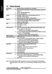
... 6 SATA 3Gb/s ports: 4 ports from MCP-04 controller (SATAII0, SATAII1, SATAII2, SATAII3) - Only for GA-8N-SLI Royal. Only for GA-8N-SLI Pro. Supported on the Win 2000/XP operating systems 1 parallel port supporting Normal/EPP/ECP mode 1 Serial port ...Chipset Š Š Š Memory Š Š Š Slots Š Š Š IDE Connections Š Š FDD Connections Š Onboard SATA 3Gb/s Š Peripherals Š Š Š Š Š Š Š Onboard LAN Š Š Š GA-8N-SLI Royal or GA-8N-SLI Pro or GA-8N-SLI...
... 6 SATA 3Gb/s ports: 4 ports from MCP-04 controller (SATAII0, SATAII1, SATAII2, SATAII3) - Only for GA-8N-SLI Royal. Only for GA-8N-SLI Pro. Supported on the Win 2000/XP operating systems 1 parallel port supporting Normal/EPP/ECP mode 1 Serial port ...Chipset Š Š Š Memory Š Š Š Slots Š Š Š IDE Connections Š Š FDD Connections Š Onboard SATA 3Gb/s Š Peripherals Š Š Š Š Š Š Š Onboard LAN Š Š Š GA-8N-SLI Royal or GA-8N-SLI Pro or GA-8N-SLI...
Manual
Page 13
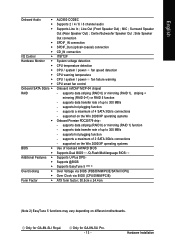
... Speaker Out) ; supports data striping (RAID 0) or mirroring (RAID 1), striping + mirroring (RAID 0+1) or RAID 5 function - supports a maximum of 2 SATA 3Gb/s connections - Only for GA-8N-SLI Royal. English Onboard Audio Š Š Š Š Š Š I/O Control Š Hardware Monitor Š Š Š Š Š Š Onboard ... detection CPU warning temperature CPU / system / power fan failure warning CPU smart fan control Onboard nVIDIA® MCP-04 chipset - Line Out (Front Speaker Out) ; supports data transfer rate of up to 300 MB/s -
... Speaker Out) ; supports data striping (RAID 0) or mirroring (RAID 1), striping + mirroring (RAID 0+1) or RAID 5 function - supports a maximum of 2 SATA 3Gb/s connections - Only for GA-8N-SLI Royal. English Onboard Audio Š Š Š Š Š Š I/O Control Š Hardware Monitor Š Š Š Š Š Š Onboard ... detection CPU warning temperature CPU / system / power fan failure warning CPU smart fan control Onboard nVIDIA® MCP-04 chipset - Line Out (Front Speaker Out) ; supports data transfer rate of up to 300 MB/s -
Manual
Page 14
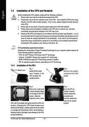
... you install the CPU in accordance with the triangle and gently insert the CPU into the socket in a straight and downwards motion. Chipset: A NVIDIA® Chipset that supports HT Technology and has it enabled - Fig. 3 Notice the small gold colored triangle located on the CPU socket to your... graphics card, memory, hard drive, etc. Fig. 2 Remove the plastic covering on the CPU prior to the CPU during installation.) P4 nForce4 SLI Series Motherboard - 14 - Please set beyond the proper specifications, please do so according to the upright position. If you wish to set the ...
... you install the CPU in accordance with the triangle and gently insert the CPU into the socket in a straight and downwards motion. Chipset: A NVIDIA® Chipset that supports HT Technology and has it enabled - Fig. 3 Notice the small gold colored triangle located on the CPU socket to your... graphics card, memory, hard drive, etc. Fig. 2 Remove the plastic covering on the CPU prior to the CPU during installation.) P4 nForce4 SLI Series Motherboard - 14 - Please set beyond the proper specifications, please do so according to the upright position. If you wish to set the ...
Manual
Page 17
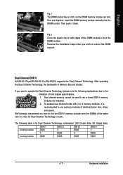
... you want to operate the Dual Channel Technology, please note the following table is recommended to work. If you wish to the limitation of Intel chipset specifications. 1. Then push it is for Dual Channel Technology to use memory modules of the same color in one or three DDR II memory modules... DS/SS DS/SS - 17 - Insert the DIMM memory module vertically into the DIMMs of identical brand, size, chips, and speed. Dual Channel DDR II GA-8N-SLI Royal/GA-8N-SLI Pro/GA-8N-SLI supports the Dual Channel Technology. Hardware Installation
... you want to operate the Dual Channel Technology, please note the following table is recommended to work. If you wish to the limitation of Intel chipset specifications. 1. Then push it is for Dual Channel Technology to use memory modules of the same color in one or three DDR II memory modules... DS/SS DS/SS - 17 - Insert the DIMM memory module vertically into the DIMMs of identical brand, size, chips, and speed. Dual Channel DDR II GA-8N-SLI Royal/GA-8N-SLI Pro/GA-8N-SLI supports the Dual Channel Technology. Hardware Installation
Manual
Page 20
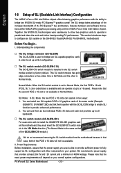
...GA-8N-SLI Royal/GA-8N-SLI Pro/GA-8N-SLI motherboard. Power Requirements: Before installation, assure that provides at up to x 16 speed. Before You Begin-- One is set up to x8 bandwidth. … The SLI switch module (GC-SLISW-3D1) For users who wish to install the GIGABYTE...and software innovations within NVIDIA GPU (graphics processing unit) and the nVIDIA nForce 4 SLI Intel Edition chipset. English 1-8 Setup of SLI (Scalable Link Interface) Configuration The nVIDIA® nForce 4 SLI Intel Edition chipset offers blistering graphics performance with the GC-SLICON bridge to enable...
...GA-8N-SLI Royal/GA-8N-SLI Pro/GA-8N-SLI motherboard. Power Requirements: Before installation, assure that provides at up to x 16 speed. Before You Begin-- One is set up to x8 bandwidth. … The SLI switch module (GC-SLISW-3D1) For users who wish to install the GIGABYTE...and software innovations within NVIDIA GPU (graphics processing unit) and the nVIDIA nForce 4 SLI Intel Edition chipset. English 1-8 Setup of SLI (Scalable Link Interface) Configuration The nVIDIA® nForce 4 SLI Intel Edition chipset offers blistering graphics performance with the GC-SLICON bridge to enable...
Manual
Page 43
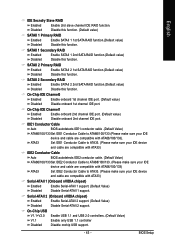
...-Chip IDE Channel0 Enabled Disabled Enable onboard 1st channel IDE port. (Default value) Disable onboard 1st channel IDE port. Serial-ATAII 2 (Onboard nVIDIA chipset) Enabled Disabled Enable Serial-ATAII 2 support. (Default Value) Disable Serial-ATAII 2 support. BIOS Setup English IDE Secndry Slave RAID Enabled Enable 2nd slave... Set IDE1 Conductor Cable to ATA33. (Please make sure your IDE device and cable are compatible with ATA33) Serial-ATAII 1 (Onboard nVIDIA chipset) Enabled Enable Serial-ATAII 1 support. (Default Value) Disabled Disable Serial-ATAII 1 support.
...-Chip IDE Channel0 Enabled Disabled Enable onboard 1st channel IDE port. (Default value) Disable onboard 1st channel IDE port. Serial-ATAII 2 (Onboard nVIDIA chipset) Enabled Disabled Enable Serial-ATAII 2 support. (Default Value) Disable Serial-ATAII 2 support. BIOS Setup English IDE Secndry Slave RAID Enabled Enable 2nd slave... Set IDE1 Conductor Cable to ATA33. (Please make sure your IDE device and cable are compatible with ATA33) Serial-ATAII 1 (Onboard nVIDIA chipset) Enabled Enable Serial-ATAII 1 support. (Default Value) Disabled Disable Serial-ATAII 1 support.
Manual
Page 53
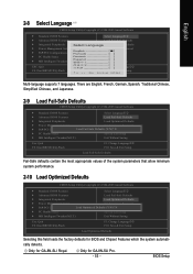
BIOS Setup Only for GA-8N-SLI Pro. - 53 - Only for GA-8N-SLI Royal. English 2-8 Select Language CMOS Setup Utility-Copyright (C) 1984-2005 Award Software ` Standard CMOS Features ` Advanced BIOS Features ` Integrated Peripherals ` Power Management... F8: Dual BIOS12/Q-Flash F3: Change Language12 F10: Save & Exit Setup Load Optimized Defaults Selecting this field loads the factory defaults for BIOS and Chipset Features which the system automatically detects. There are English, French, German, Spanish, Traditional Chinese, Simplified Chinese, and Japanese. 2-9 Load Fail-Safe Defaults...
BIOS Setup Only for GA-8N-SLI Pro. - 53 - Only for GA-8N-SLI Royal. English 2-8 Select Language CMOS Setup Utility-Copyright (C) 1984-2005 Award Software ` Standard CMOS Features ` Advanced BIOS Features ` Integrated Peripherals ` Power Management... F8: Dual BIOS12/Q-Flash F3: Change Language12 F10: Save & Exit Setup Load Optimized Defaults Selecting this field loads the factory defaults for BIOS and Chipset Features which the system automatically detects. There are English, French, German, Spanish, Traditional Chinese, Simplified Chinese, and Japanese. 2-9 Load Fail-Safe Defaults...

Manual
Page 57
...right USB2.0 driver). Only for you want then click the "GO" button. After install Windows Service Pack, it will execute the installation for GA-8N-SLI Royal. - 57 - For USB2.0 driver support under "Device Manager". Please remove the question mark and restart the system (System will reboot .... Drivers Installation If not, please double click the CD-ROM device icon in "My computer", and execute the Setup.exe. 3-1 Install Chipset Drivers After insert the driver CD, "Xpress Install" will scan automatically the system and then list all the drivers that came with your...
...right USB2.0 driver). Only for you want then click the "GO" button. After install Windows Service Pack, it will execute the installation for GA-8N-SLI Royal. - 57 - For USB2.0 driver support under "Device Manager". Please remove the question mark and restart the system (System will reboot .... Drivers Installation If not, please double click the CD-ROM device icon in "My computer", and execute the Setup.exe. 3-1 Install Chipset Drivers After insert the driver CD, "Xpress Install" will scan automatically the system and then list all the drivers that came with your...
Manual
Page 62
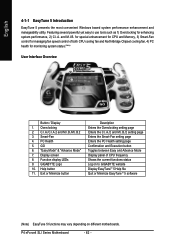
.../ Display 1. C.I.A./C.I.A.2 and M.I.B./M.I .B. Exit or Minimize button Description Enters the Overclocking setting page Enters the C.I.A./2 and M.I .A. Smart-Fan 4. GIGABYTE Logo 10. Help button 11. P4 nForce4 SLI Series Motherboard - 62 - GO 6. "Easy Mode" & "Advance Mode" 7. Display screen 8. Overclocking 2. PC Health 5. and M.I .B.2...Execution button Toggles between Easy and Advance Mode Display panel of both CPU cooling fan and North-Bridge Chipset cooling fan, 4) PC health for managing fan speed control of CPU frequency Shows the current functions status Log...
.../ Display 1. C.I.A./C.I.A.2 and M.I.B./M.I .B. Exit or Minimize button Description Enters the Overclocking setting page Enters the C.I.A./2 and M.I .A. Smart-Fan 4. GIGABYTE Logo 10. Help button 11. P4 nForce4 SLI Series Motherboard - 62 - GO 6. "Easy Mode" & "Advance Mode" 7. Display screen 8. Overclocking 2. PC Health 5. and M.I .B.2...Execution button Toggles between Easy and Advance Mode Display panel of both CPU cooling fan and North-Bridge Chipset cooling fan, 4) PC health for managing fan speed control of CPU frequency Shows the current functions status Log...
Manual
Page 64
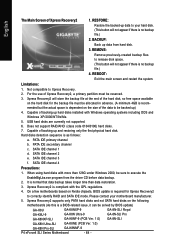
... update) GA-K8U GA-K8NXP-9 GA-8N-SLI Royal GA-K8U-9 GA-K8N Ultra-9 GA-8N-SLI Pro GA-K8NXP-SLI GA-K8NF-9 (PCB Ver. 1.0) GA-8N-SLI GA-K8N Ultra-SLI GA-K8NE (PCB Ver. 1.0) GA-K8N Pro-SLI GA-K8NMF-9 P4 nForce4 SLI Series Motherboard - 64 - Hard disks detection sequence is compliant with Windows operating systems including DOS and Windows XP/2000/NT/9x/Me. 5. It is dependent on Nvidia chipsets, BIOS...
... update) GA-K8U GA-K8NXP-9 GA-8N-SLI Royal GA-K8U-9 GA-K8N Ultra-9 GA-8N-SLI Pro GA-K8NXP-SLI GA-K8NF-9 (PCB Ver. 1.0) GA-8N-SLI GA-K8N Ultra-SLI GA-K8NE (PCB Ver. 1.0) GA-K8N Pro-SLI GA-K8NMF-9 P4 nForce4 SLI Series Motherboard - 64 - Hard disks detection sequence is compliant with Windows operating systems including DOS and Windows XP/2000/NT/9x/Me. 5. It is dependent on Nvidia chipsets, BIOS...
Manual
Page 76
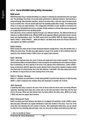
...data and parity. Different RAID levels represent different performance levels, security levels and implementation costs. the RAID levels which the nVIDIA® MCP-04 chipset supports are RAID 0 and RAID 1. If any data loss. The individual disk drives in the array. RAID 0+1 (Striping + Mirroring) ...data onto a drive until it affects the entire array. RAID 5 (Striping with Parity) RAID 5 provides good fault tolerance and allows for GA-8N-SLI Royal. After replacing the failed drive, you can be affected as long as there are other working drives in an array are recognized as ...
...data and parity. Different RAID levels represent different performance levels, security levels and implementation costs. the RAID levels which the nVIDIA® MCP-04 chipset supports are RAID 0 and RAID 1. If any data loss. The individual disk drives in the array. RAID 0+1 (Striping + Mirroring) ...data onto a drive until it affects the entire array. RAID 5 (Striping with Parity) RAID 5 provides good fault tolerance and allows for GA-8N-SLI Royal. After replacing the failed drive, you can be affected as long as there are other working drives in an array are recognized as ...


