Manual
Page 6
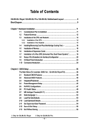
Table of Contents GA-8N-SLI Royal / GA-8N-SLI Pro / GA-8N-SLI Motherboard Layout 8 Block Diagram ...9 Chapter 1 Hardware Installation 11 1-1 Considerations Prior to Installation 11 1-2 Feature Summary 12 1-3 Installation of the CPU and Heatsink 14 1-3-1 Installation of the CPU 14 1-3-2 Installation of the Heatsink 15 1-4 Installing/Removing Cool-Plus (Northbridge Cooling Fan 16 1-5 Installation of Memory 16 1-6 Installation of Expansion...
Table of Contents GA-8N-SLI Royal / GA-8N-SLI Pro / GA-8N-SLI Motherboard Layout 8 Block Diagram ...9 Chapter 1 Hardware Installation 11 1-1 Considerations Prior to Installation 11 1-2 Feature Summary 12 1-3 Installation of the CPU and Heatsink 14 1-3-1 Installation of the CPU 14 1-3-2 Installation of the Heatsink 15 1-4 Installing/Removing Cool-Plus (Northbridge Cooling Fan 16 1-5 Installation of Memory 16 1-6 Installation of Expansion...
Manual
Page 9
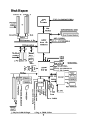
Only for GA-8N-SLI Royal. Block Diagram 1 PCIE x 16 2 PCIE x 8 PCI-ECLK (100MHz) or LGA775 Processor CPUCLK+/-(1066/800/533MHz) Host Interface DDRII 667/533MHz DIMM Normal Mode SLI Mode Switch PCI Express x 16 Bus PCI Express Bus x1 x1 x1 nVIDIA® nForce 4 SLI Intel Edition Dual Channel Memory NBCLK (25MHz) HCLK+/- (133/200/266MHz) PCI... Channel 3 IEEE1394b Surround Speaker Out Center/Subwoofer Speaker Out Side Speaker Out MIC Line-Out Line-In SPDIF In SPDIF Out PCICLK (33MHz) Only for GA-8N-SLI Pro. - 9 -
Only for GA-8N-SLI Royal. Block Diagram 1 PCIE x 16 2 PCIE x 8 PCI-ECLK (100MHz) or LGA775 Processor CPUCLK+/-(1066/800/533MHz) Host Interface DDRII 667/533MHz DIMM Normal Mode SLI Mode Switch PCI Express x 16 Bus PCI Express Bus x1 x1 x1 nVIDIA® nForce 4 SLI Intel Edition Dual Channel Memory NBCLK (25MHz) HCLK+/- (133/200/266MHz) PCI... Channel 3 IEEE1394b Surround Speaker Out Center/Subwoofer Speaker Out Side Speaker Out MIC Line-Out Line-In SPDIF In SPDIF Out PCICLK (33MHz) Only for GA-8N-SLI Pro. - 9 -
Manual
Page 12
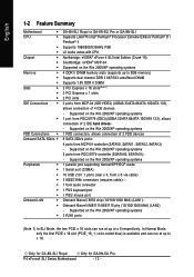
...; CPU Š Š Š Chipset Š Š Š Memory Š Š Š Slots Š Š Š IDE Connections Š Š FDD Connections Š Onboard SATA 3Gb/s Š Peripherals Š Š Š Š Š Š Š Onboard LAN Š Š Š GA-8N-SLI Royal or GA-8N-SLI Pro or GA-8N-SLI Supports LGA775 Intel® Pentium® Processor Extreme...
...; CPU Š Š Š Chipset Š Š Š Memory Š Š Š Slots Š Š Š IDE Connections Š Š FDD Connections Š Onboard SATA 3Gb/s Š Peripherals Š Š Š Š Š Š Š Onboard LAN Š Š Š GA-8N-SLI Royal or GA-8N-SLI Pro or GA-8N-SLI Supports LGA775 Intel® Pentium® Processor Extreme...
Manual
Page 14
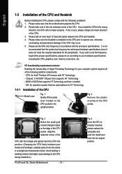
... Technology and has it does not meet the required standards for your hardware specifications including the CPU, graphics card, memory, hard drive, etc. If you wish to the CPU during installation.) P4 nForce4 SLI Series Motherboard - 14 - Chipset: A NVIDIA® Chipset that might cause damage to set the CPU host frequency in...
... Technology and has it does not meet the required standards for your hardware specifications including the CPU, graphics card, memory, hard drive, etc. If you wish to the CPU during installation.) P4 nForce4 SLI Series Motherboard - 14 - Chipset: A NVIDIA® Chipset that might cause damage to set the CPU host frequency in...
Manual
Page 16
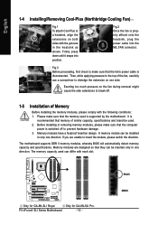
... sure that they can differ with each slot. Exerting too much pressure on one side. Only for GA-8N-SLI Royal. Memory modules have a foolproof insertion design. Memory modules are unable to insert the module, please switch the direction. The memory capacity used is properly affixed onto the heatsink, plug the power cable into position. English 1-4 Installing...
... sure that they can differ with each slot. Exerting too much pressure on one side. Only for GA-8N-SLI Royal. Memory modules have a foolproof insertion design. Memory modules are unable to insert the module, please switch the direction. The memory capacity used is properly affixed onto the heatsink, plug the power cable into position. English 1-4 Installing...
Manual
Page 17
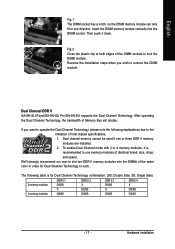
... Then push it is for Dual Channel Technology to slot two DDR II memory modules into the DIMM socket. If you wish to use memory modules of the same color in one or three DDR II memory modules are installed. 2. English Fig.1 The DIMM socket has a notch,... The following explanations due to lock the DIMM module. Hardware Installation Insert the DIMM memory module vertically into the DIMMs of identical brand, size, chips, and speed. Dual Channel DDR II GA-8N-SLI Royal/GA-8N-SLI Pro/GA-8N-SLI supports the Dual Channel Technology. Fig.2 Close the plastic clip at both edges of ...
... Then push it is for Dual Channel Technology to slot two DDR II memory modules into the DIMM socket. If you wish to use memory modules of the same color in one or three DDR II memory modules are installed. 2. English Fig.1 The DIMM socket has a notch,... The following explanations due to lock the DIMM module. Hardware Installation Insert the DIMM memory module vertically into the DIMMs of identical brand, size, chips, and speed. Dual Channel DDR II GA-8N-SLI Royal/GA-8N-SLI Pro/GA-8N-SLI supports the Dual Channel Technology. Fig.2 Close the plastic clip at both edges of ...
Manual
Page 38
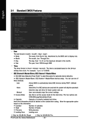
Halt On Base Memory Extended Memory Total Memory [All, But Keyboard] 640K 511M 512M 1 to 31 (or maximum allowed in the... CHS/LBA/Large/Auto(default:Auto) Capacity Capacity of heads Precomp Write precomp Landing Zone Landing zone Only for GA-8N-SLI Royal. Hard drive information should be labeled on the 24-hour military-time clock. Day The day, from 1 ...to 31 (or the maximum allowed in the month) < Ye a r > 1999 to set the access mode for GA-8N-SLI Pro. IDE Channel 0 Master/Slave; Manual User can use one of three methods: Auto Allows BIOS to automatically detect IDE ...
Halt On Base Memory Extended Memory Total Memory [All, But Keyboard] 640K 511M 512M 1 to 31 (or maximum allowed in the... CHS/LBA/Large/Auto(default:Auto) Capacity Capacity of heads Precomp Write precomp Landing Zone Landing zone Only for GA-8N-SLI Royal. Hard drive information should be labeled on the 24-hour military-time clock. Day The day, from 1 ...to 31 (or the maximum allowed in the month) < Ye a r > 1999 to set the access mode for GA-8N-SLI Pro. IDE Channel 0 Master/Slave; Manual User can use one of three methods: Auto Allows BIOS to automatically detect IDE ...
Manual
Page 39
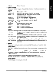
...Test) of the BIOS. BIOS Setup Floppy 3 Mode Support (for any error that may be detected and you ill be stopped. Total Memory This item displays the memory size that used. - 39 - English Sector Number of sectors Drive A / Drive B The category identifies the types of floppy disk ...it will stop for all other errors. (Default value) All, But Diskette The system boot will determine the amount of memory located above 1 MB in the CPU's memory address map. Memory The category is display-only which is 3 mode Floppy Drive. None No floppy drive installed. 360K, 5.25" 1.2M...
...Test) of the BIOS. BIOS Setup Floppy 3 Mode Support (for any error that may be detected and you ill be stopped. Total Memory This item displays the memory size that used. - 39 - English Sector Number of sectors Drive A / Drive B The category identifies the types of floppy disk ...it will stop for all other errors. (Default value) All, But Diskette The system boot will determine the amount of memory located above 1 MB in the CPU's memory address map. Memory The category is display-only which is 3 mode Floppy Drive. None No floppy drive installed. 360K, 5.25" 1.2M...
Manual
Page 40
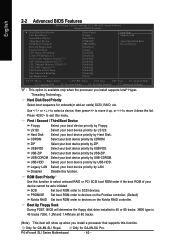
...Hard Disk Select your boot device priority by USB-HDD. USB-ZIP Select your boot device priority by LAN. P4 nForce4 SLI Series Motherboard - 40 - Hard Disk Boot Priority Select boot sequence for onboard(or add-on the Nvidia RAID controller.... by ZIP. Only for GA-8N-SLI Royal. USB-FDD Select your boot device priority by USB-FDD. ROM Boot Priority Use this function. SCSI Set boot ROM order to move it down the list. Press to 3 No-Execute Memory Protect (Note) CPU Enhanced... CPU Hyper-Threading # Limit CPUID Max. to exit this function. Only for GA-8N-SLI Pro.
...Hard Disk Select your boot device priority by USB-HDD. USB-ZIP Select your boot device priority by LAN. P4 nForce4 SLI Series Motherboard - 40 - Hard Disk Boot Priority Select boot sequence for onboard(or add-on the Nvidia RAID controller.... by ZIP. Only for GA-8N-SLI Royal. USB-FDD Select your boot device priority by USB-FDD. ROM Boot Priority Use this function. SCSI Set boot ROM order to move it down the list. Press to 3 No-Execute Memory Protect (Note) CPU Enhanced... CPU Hyper-Threading # Limit CPUID Max. to exit this function. Only for GA-8N-SLI Pro.
Manual
Page 41
... Maximum value to 3 when using older OS like NT4. Enabled Enable CPU Hyper-Threading feature. Disable CPUID Limit for Windows XP.(Default value) No-Execute Memory Protect (Note) Enabled Enable No-Execute Memory Protect function.(Default value) Disabled Disable No-Execute...
... Maximum value to 3 when using older OS like NT4. Enabled Enable CPU Hyper-Threading feature. Disable CPUID Limit for Windows XP.(Default value) No-Execute Memory Protect (Note) Enabled Enable No-Execute Memory Protect function.(Default value) Disabled Disable No-Execute...

Manual
Page 51
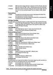
Type in New FSB Speed (QDR). SLI Broadcast Aperture Auto Set SLI Broadcast Aperture to set the FSB speed. Disabled Disable this function. (Default value) DIMM OverVoltage Control Normal Set DIMM OverVoltage Control to Normal. (Default value) +0.... FSB Speed (QDR) and New MEM Speed (DDR). BIOS Setup New FSB Speed (QDR) This item becomes active when System Clock Mode is set the memory speed. New MEM Speed (DDR) This item becomes active when System Clock Mode is set to set to +0.3V. - 51 - PCI-E OverVoltage Control Normal Set...
Type in New FSB Speed (QDR). SLI Broadcast Aperture Auto Set SLI Broadcast Aperture to set the FSB speed. Disabled Disable this function. (Default value) DIMM OverVoltage Control Normal Set DIMM OverVoltage Control to Normal. (Default value) +0.... FSB Speed (QDR) and New MEM Speed (DDR). BIOS Setup New FSB Speed (QDR) This item becomes active when System Clock Mode is set the memory speed. New MEM Speed (DDR) This item becomes active when System Clock Mode is set to set to +0.3V. - 51 - PCI-E OverVoltage Control Normal Set...
Manual
Page 61
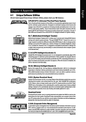
...battery on the U-Plus D.P.S. allows corporate MIS engineers to easily maintain corporate computers such as the CPU system bus, memory timings or to enabled Gigabyte's unique C.I.A. 2 and M.I .T.) allows user to maximize system performance. Designed to -date drivers and BIOS.(Do ...and ease. As well, 4 blue LED's are able to 10%. Through GIGABYTE M.I .A. 2) is designed especially to maximize memory performance and boost memory bandwidth up errors resulting from a recommended memory module list. S.O.S. (System Overclock Saver) System Overclock Saver (S.O.S.) is a revolutionary...
...battery on the U-Plus D.P.S. allows corporate MIS engineers to easily maintain corporate computers such as the CPU system bus, memory timings or to enabled Gigabyte's unique C.I.A. 2 and M.I .T.) allows user to maximize system performance. Designed to -date drivers and BIOS.(Do ...and ease. As well, 4 blue LED's are able to 10%. Through GIGABYTE M.I .A. 2) is designed especially to maximize memory performance and boost memory bandwidth up errors resulting from a recommended memory module list. S.O.S. (System Overclock Saver) System Overclock Saver (S.O.S.) is a revolutionary...
Manual
Page 62
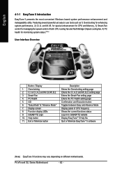
... Overclocking for monitoring system status.(Note) User Interface Overview Button / Display 1. GIGABYTE Logo 10. and M.I .B./2 setting page Enters the Smart-Fan setting page Enters...setting page Enters the C.I.A./2 and M.I .B. C.I.A./C.I.A.2 and M.I.B./M.I .A. for special enhancement for CPU and Memory, 3) Smart-Fan control for managing fan speed control of CPU frequency Shows the current functions status Log...Help button 11. "Easy Mode" & "Advance Mode" 7. P4 nForce4 SLI Series Motherboard - 62 - English 4-1-1 EasyTune 5 Introduction EasyTune 5 presents the most convenient ...
... Overclocking for monitoring system status.(Note) User Interface Overview Button / Display 1. GIGABYTE Logo 10. and M.I .B./2 setting page Enters the Smart-Fan setting page Enters...setting page Enters the C.I.A./2 and M.I .B. C.I.A./C.I.A.2 and M.I.B./M.I .A. for special enhancement for CPU and Memory, 3) Smart-Fan control for managing fan speed control of CPU frequency Shows the current functions status Log...Help button 11. "Easy Mode" & "Advance Mode" 7. P4 nForce4 SLI Series Motherboard - 62 - English 4-1-1 EasyTune 5 Introduction EasyTune 5 presents the most convenient ...
Manual
Page 63
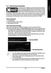
... the provided driver CD into your hard disk. Upon system restart, the message which says "Boot from CD/DVD:" will affect the data backup speed. 3. GA-8N-SLI Royal F5a . . . . :BIOS Setup/Q-Flash, : Xpress Recovery2, For Boot Menu 11/16/2005-C19-MCP04-6A61EG0FC-00 Xpress Recovery2 1. Press any key... your CD-ROM drive. System requirements: 1. Save the settings and exit the BIOS Setup. System storage capacity and the reading/writing speed of system memory 3. It is designed to back up data on hard disks on . . . Boot from CD-ROM and subsequent access by pressing the F9 key...
... the provided driver CD into your hard disk. Upon system restart, the message which says "Boot from CD/DVD:" will affect the data backup speed. 3. GA-8N-SLI Royal F5a . . . . :BIOS Setup/Q-Flash, : Xpress Recovery2, For Boot Menu 11/16/2005-C19-MCP04-6A61EG0FC-00 Xpress Recovery2 1. Press any key... your CD-ROM drive. System requirements: 1. Save the settings and exit the BIOS Setup. System storage capacity and the reading/writing speed of system memory 3. It is designed to back up data on hard disks on . . . Boot from CD-ROM and subsequent access by pressing the F9 key...
Manual
Page 67
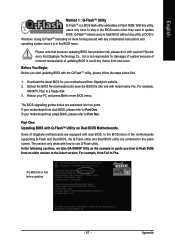
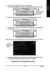
... OK Memory Frequency 266 MHz in the BIOS menu. Appendix Extract the BIOS file downloaded and save the BIOS file (the one with Q-FlashTM Utility on Dual BIOS Motherboards. In the BIOS menu of Gigabyte motherboards ...version to the latest version. Reboot your motherboard has single-BIOS, please refer to Fba. For example, from Gigabyte's website. 2. Q-FlashTM allows users to update BIOS. If your motherboard from Fa3 to Part Two. With...separated into two parts. In the following sections, we take GA-8KNXP Ultra as the example to guide you start updating BIOS with caution!!
... OK Memory Frequency 266 MHz in the BIOS menu. Appendix Extract the BIOS file downloaded and save the BIOS file (the one with Q-FlashTM Utility on Dual BIOS Motherboards. In the BIOS menu of Gigabyte motherboards ...version to the latest version. Reboot your motherboard has single-BIOS, please refer to Fba. For example, from Gigabyte's website. 2. Q-FlashTM allows users to update BIOS. If your motherboard from Fa3 to Part Two. With...separated into two parts. In the following sections, we take GA-8KNXP Ultra as the example to guide you start updating BIOS with caution!!
Manual
Page 70
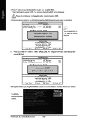
..., Award Software, Inc. Intel i875P AGPset BIOS for 8KNXP Ultra Fba Check System Health OK , VCore = 1.5250 Main Processor : Intel Pentium(R) 4 1.6GHz (133x12) Memory Testing : 131072K OK Memory Frequency 266 MHz in Single Channel Primary Master : FUJITSU MPE3170AT ED-03-08 Primary Slave : None Secondary Master : CREATIVEDVD-RM DVD1242E BC101 Secondary Slave...:Power Off You can repeat Step 1 to 4 to enter SETUP / Dual BIOS / Q-Flash / F9 For Xpress Recovery 09/23/2003-i875P-6A79BG03C-00 P4 nForce4 SLI Series Motherboard - 70 - Pass !!
..., Award Software, Inc. Intel i875P AGPset BIOS for 8KNXP Ultra Fba Check System Health OK , VCore = 1.5250 Main Processor : Intel Pentium(R) 4 1.6GHz (133x12) Memory Testing : 131072K OK Memory Frequency 266 MHz in Single Channel Primary Master : FUJITSU MPE3170AT ED-03-08 Primary Slave : None Secondary Master : CREATIVEDVD-RM DVD1242E BC101 Secondary Slave...:Power Off You can repeat Step 1 to 4 to enter SETUP / Dual BIOS / Q-Flash / F9 For Xpress Recovery 09/23/2003-i875P-6A79BG03C-00 P4 nForce4 SLI Series Motherboard - 70 - Pass !!
Manual
Page 73
... (C) 1984-2003, Award Software, Inc. Intel 845GE AGPSet BIOS for 8GE800 F4 Check System Health OK Main Processor : Intel Pentium(R) 4 1.7GHz (100x17.0) Memory Testing : 122880K OK + 8192K Shared Memory Primary Master : FUJITSU MPE3170AT ED-03-08 Primary Slave : None Secondary Master : CREATIVEDVD-RM DVD1242E BC101 Secondary Slave : None Press DEL to 7 in...
... (C) 1984-2003, Award Software, Inc. Intel 845GE AGPSet BIOS for 8GE800 F4 Check System Health OK Main Processor : Intel Pentium(R) 4 1.7GHz (100x17.0) Memory Testing : 122880K OK + 8192K Shared Memory Primary Master : FUJITSU MPE3170AT ED-03-08 Primary Slave : None Secondary Master : CREATIVEDVD-RM DVD1242E BC101 Secondary Slave : None Press DEL to 7 in...
Manual
Page 91
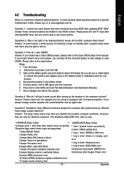
... the steps below may help you identify the possible computer problems. However, they are always fatal. 1 beep Refresh failure 2 beeps Parity error 3 beeps Base 64K memory failure 4 beeps Timer not operational 5 beeps Processor error 2 short: CMOS setting error 1 long 1 short: DRAM or M/B error 1 long 2 short: Monitor or ... later. English 4-2 Troubleshooting Below is a collection of general asked questions based on a specific motherboard model, please log on to www.gigabyte.com.tw Question 1: I cannot see these beeps usually stand for about 10 minutes (Or you can take off power. 2.
... the steps below may help you identify the possible computer problems. However, they are always fatal. 1 beep Refresh failure 2 beeps Parity error 3 beeps Base 64K memory failure 4 beeps Timer not operational 5 beeps Processor error 2 short: CMOS setting error 1 long 1 short: DRAM or M/B error 1 long 2 short: Monitor or ... later. English 4-2 Troubleshooting Below is a collection of general asked questions based on a specific motherboard model, please log on to www.gigabyte.com.tw Question 1: I cannot see these beeps usually stand for about 10 minutes (Or you can take off power. 2.

Manual
Page 5
... CPU Hyper-Threading # Limit CPUID Max. to CD-ROM (Figure 5). SATA Configurations (P4 nForce4 SLI series) Step 3: To boot from Windows installation CD-ROM, set First Boot Device under the Advanced BIOS Features menu to 3 No-Execute Memory Protect CPU Enhanced Halt (C1E) CPU Thermal Monitor 2(TM2) CPU EIST Function Full Screen...
... CPU Hyper-Threading # Limit CPUID Max. to CD-ROM (Figure 5). SATA Configurations (P4 nForce4 SLI series) Step 3: To boot from Windows installation CD-ROM, set First Boot Device under the Advanced BIOS Features menu to 3 No-Execute Memory Protect CPU Enhanced Halt (C1E) CPU Thermal Monitor 2(TM2) CPU EIST Function Full Screen...
Manual
Page 6
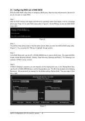
... Disk Model Name [g] Add [f ] Del [ESC] Quit [F6] Back [F7] Finish [TAB] Navigate [hi] Select [ENTER] Popup Figure 7 SATA Configurations (P4 nForce4 SLI series) - 6 - You can manually set the striping block size. The KB is from 4K to select a RAID mode. Define a New Array - Step 3: In the ...2005 - The following is the first option screen when you do not want to create RAID. ¤¤ Step 1: ¤å After the POST memory test begins and before the operating system boot begins, look for a message which says "Press F10 to configure a RAID array. Skip this step and ...
... Disk Model Name [g] Add [f ] Del [ESC] Quit [F6] Back [F7] Finish [TAB] Navigate [hi] Select [ENTER] Popup Figure 7 SATA Configurations (P4 nForce4 SLI series) - 6 - You can manually set the striping block size. The KB is from 4K to select a RAID mode. Define a New Array - Step 3: In the ...2005 - The following is the first option screen when you do not want to create RAID. ¤¤ Step 1: ¤å After the POST memory test begins and before the operating system boot begins, look for a message which says "Press F10 to configure a RAID array. Skip this step and ...


