Manual
Page 1
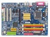
GA-8I945G Pro/ GA-8I945G Intel® Pentium® D / Pentium® 4 LGA775 Processor Motherboard User's Manual Rev. 1005 12ME-8I945GP-1005 * The WEEE marking on the product indicates this product must not be disposed of with user's other household waste and must be handed over to a designated collection point for the recycling of waste electrical and electronic equipment!! * The WEEE marking applies only in European Union's member states.
GA-8I945G Pro/ GA-8I945G Intel® Pentium® D / Pentium® 4 LGA775 Processor Motherboard User's Manual Rev. 1005 12ME-8I945GP-1005 * The WEEE marking on the product indicates this product must not be disposed of with user's other household waste and must be handed over to a designated collection point for the recycling of waste electrical and electronic equipment!! * The WEEE marking applies only in European Union's member states.

Manual
Page 4
Table of Contents GA-8I945G Pro Motherboard Layout 6 GA-8I945G Motherboard Layout 7 Block Diagram ...8 Chapter 1 Hardware Installation 9 1-1 Considerations Prior to Installation 9 1-2 Feature Summary 10 1-3 Installation of the CPU and Heatsink 12...of Expansion Cards 16 1-7 I/O Back Panel Introduction 17 1-8 Connectors Introduction 18 Chapter 2 BIOS Setup 29 The Main Menu (For example: BIOS Ver. : GA-8I945G Pro F2d 30 2-1 Standard CMOS Features 32 2-2 Advanced BIOS Features 34 2-3 IntegratedPeripherals 36 2-4 Power Management Setup 39 2-5 PnP/PCI Configurations 41 2-6 PC Health ...
Table of Contents GA-8I945G Pro Motherboard Layout 6 GA-8I945G Motherboard Layout 7 Block Diagram ...8 Chapter 1 Hardware Installation 9 1-1 Considerations Prior to Installation 9 1-2 Feature Summary 10 1-3 Installation of the CPU and Heatsink 12...of Expansion Cards 16 1-7 I/O Back Panel Introduction 17 1-8 Connectors Introduction 18 Chapter 2 BIOS Setup 29 The Main Menu (For example: BIOS Ver. : GA-8I945G Pro F2d 30 2-1 Standard CMOS Features 32 2-2 Advanced BIOS Features 34 2-3 IntegratedPeripherals 36 2-4 Power Management Setup 39 2-5 PnP/PCI Configurations 41 2-6 PC Health ...

Manual
Page 6
GA-8I945G Pro Motherboard Layout KB_MS ATX_12V CPU_FAN COAXIAL LGA775 ATX OPTICAL PWR_FAN LPT LAN VGA GA-8I945G Pro R_USB USB FDD AUDIO1 AUDIO2 F_AUDIO Intel 945G Broadcom 5789 CD_IN CODEC IT8712 NB_FAN PCIE_16 PCIE_1 PCIE_2 Main BIOS Back BIOS ICH7R PCI1 TSB82AA2 PCI2 SATAII0 IT8212 SATAII1 DDRII1 DDRII2 SATAII2 SATAII3 DDRII3 DDRII4 IDE1 IDE3 IDE2 SYS_FAN COMA CI RF_ID SPDIF_I PCI3 TSB81BA3 BAT F_USB GREEN_USB F1_1394 F2_1394 F_PANEL PWR_LED (Optional) CLR_CMOS - 6 -
GA-8I945G Pro Motherboard Layout KB_MS ATX_12V CPU_FAN COAXIAL LGA775 ATX OPTICAL PWR_FAN LPT LAN VGA GA-8I945G Pro R_USB USB FDD AUDIO1 AUDIO2 F_AUDIO Intel 945G Broadcom 5789 CD_IN CODEC IT8712 NB_FAN PCIE_16 PCIE_1 PCIE_2 Main BIOS Back BIOS ICH7R PCI1 TSB82AA2 PCI2 SATAII0 IT8212 SATAII1 DDRII1 DDRII2 SATAII2 SATAII3 DDRII3 DDRII4 IDE1 IDE3 IDE2 SYS_FAN COMA CI RF_ID SPDIF_I PCI3 TSB81BA3 BAT F_USB GREEN_USB F1_1394 F2_1394 F_PANEL PWR_LED (Optional) CLR_CMOS - 6 -
Manual
Page 8
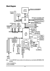
... Speaker Out Side Speaker Out MIC Line-Out Line-In SPDIF In SPDIF Out PCICLK (33MHz) (Note) To use a DDRII 667 memory module on the motherboard, you must install an 800/1066MHz FSB processor . Only for GA-8I945G Pro. Only for GA-8I945G. - 8 -
... Speaker Out Side Speaker Out MIC Line-Out Line-In SPDIF In SPDIF Out PCICLK (33MHz) (Note) To use a DDRII 667 memory module on the motherboard, you must install an 800/1066MHz FSB processor . Only for GA-8I945G Pro. Only for GA-8I945G. - 8 -

Manual
Page 10
... chip (10/100/1000 Mbit) 1 RJ 45 port Supported on the Win 2000/XP operating systems (Note 1) For further CPU support information, please go to GIGABYTE's website. (Note 2) Due to 4GB memory) (Note 2) Supports 1.8V DDR II DIMM Supports dual channel DDR II 667(Note 3)/533/400 DIMM 1 PCI Express x 16... (UDMA 33/ATA 66/ATA 100/ATA 133), compatible with CPU Northbridge: Intel® 945G Express Chipset Southbridge: Intel® ICH7R / ICH7 Supported on the motherboard, you must install an 800/1066MHz FSB processor . GA-8I945G Pro/GA-8I945G Motherboard - 10 - Only for GA-8I945G Pro.
... chip (10/100/1000 Mbit) 1 RJ 45 port Supported on the Win 2000/XP operating systems (Note 1) For further CPU support information, please go to GIGABYTE's website. (Note 2) Due to 4GB memory) (Note 2) Supports 1.8V DDR II DIMM Supports dual channel DDR II 667(Note 3)/533/400 DIMM 1 PCI Express x 16... (UDMA 33/ATA 66/ATA 100/ATA 133), compatible with CPU Northbridge: Intel® 945G Express Chipset Southbridge: Intel® ICH7R / ICH7 Supported on the motherboard, you must install an 800/1066MHz FSB processor . GA-8I945G Pro/GA-8I945G Motherboard - 10 - Only for GA-8I945G Pro.

Manual
Page 12
...between your hardware specifications including the CPU, graphics card, memory, hard drive, etc. If you wish to the CPU during installation.) GA-8I945G Pro/GA-8I945G Motherboard - 12 - Please add an even layer of the CPU and Heatsink Before installing the CPU, please comply with the processor specifications...position. Please set the frequency beyond hardware specifications since it into its original position. OS: An operation system that the motherboard supports the CPU. 2. Please make sure the heatsink is properly inserted, please replace the load plate and push the ...
...between your hardware specifications including the CPU, graphics card, memory, hard drive, etc. If you wish to the CPU during installation.) GA-8I945G Pro/GA-8I945G Motherboard - 12 - Please add an even layer of the CPU and Heatsink Before installing the CPU, please comply with the processor specifications...position. Please set the frequency beyond hardware specifications since it into its original position. OS: An operation system that the motherboard supports the CPU. 2. Please make sure the heatsink is properly inserted, please replace the load plate and push the ...
Manual
Page 14
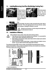
...are designed so that the fan's power cable is properly affixed onto the heatsink, plug the power cable into position. Only for GA-8I945G Pro. GA-8I945G Pro/GA-8I945G Motherboard - 14 - Exerting too much pressure on the fan during removal might cause the side extensions to insert the module, please ...snaps into the NB_FAN connector. Fig.2 Once the fan is disconnected. It is recommended that the computer power is supported by the motherboard. English 1-4 Installing/Removing Cool-Plus (Northbridge Cooling Fan) Fig.1 To attach Cool-Plus to dislodge the extension on one side....
...are designed so that the fan's power cable is properly affixed onto the heatsink, plug the power cable into position. Only for GA-8I945G Pro. GA-8I945G Pro/GA-8I945G Motherboard - 14 - Exerting too much pressure on the fan during removal might cause the side extensions to insert the module, please ...snaps into the NB_FAN connector. Fig.2 Once the fan is disconnected. It is recommended that the computer power is supported by the motherboard. English 1-4 Installing/Removing Cool-Plus (Northbridge Cooling Fan) Fig.1 To attach Cool-Plus to dislodge the extension on one side....

Manual
Page 16
Press the expansion card firmly into the computer. 2. Remove your computer's chassis cover. 7. GA-8I945G Pro/GA-8I945G Motherboard - 16 - English 1-6 Installation of Expansion Cards You can install your VGA card is locked by following the steps outlined below: 1. Read the related... instruction document before install the expansion card into expansion slot in the slot. 5. Be sure the metal contacts on the card are indeed seated in motherboard. 4. Installing a PCI Express x 16 expansion card: Please align the VGA card to release the card. Make sure your expansion card by the ...
Press the expansion card firmly into the computer. 2. Remove your computer's chassis cover. 7. GA-8I945G Pro/GA-8I945G Motherboard - 16 - English 1-6 Installation of Expansion Cards You can install your VGA card is locked by following the steps outlined below: 1. Read the related... instruction document before install the expansion card into expansion slot in the slot. 5. Be sure the metal contacts on the card are indeed seated in motherboard. 4. Installing a PCI Express x 16 expansion card: Please align the VGA card to release the card. Make sure your expansion card by the ...

Manual
Page 18
...In jack ( ) . In addition to the default speakers settings, the ~ audio jacks can be reconfigured to Center/Subwoofer Speaker Out jack. GA-8I945G Pro/GA-8I945G Motherboard - 18 - channel audio setup steps for detailed software configuration information. 1-8 Connectors Introduction 1 3 2 5 7 6 8 10 9 8 ... CI 9) SATAII0 / SATAII1 / SATAII2 / SATAII3 20) CLR_CMOS 10) F_AUDIO 21) BAT 11) PWR_LED (Optional) Only for GA-8I945G Pro. Side Speaker Out The default Side Speaker Out jack. Only microphones still MUST be connected to perform different functions via the audio software...
...In jack ( ) . In addition to the default speakers settings, the ~ audio jacks can be reconfigured to Center/Subwoofer Speaker Out jack. GA-8I945G Pro/GA-8I945G Motherboard - 18 - channel audio setup steps for detailed software configuration information. 1-8 Connectors Introduction 1 3 2 5 7 6 8 10 9 8 ... CI 9) SATAII0 / SATAII1 / SATAII2 / SATAII3 20) CLR_CMOS 10) F_AUDIO 21) BAT 11) PWR_LED (Optional) Only for GA-8I945G Pro. Side Speaker Out The default Side Speaker Out jack. Only microphones still MUST be connected to perform different functions via the audio software...

Manual
Page 20
... designed with color-coded power connector wires. Sometimes will not work. Definition 1 +12V 2 GND 1 Only for CPU_FAN) power connector and possesses a foolproof connection design. GA-8I945G Pro/GA-8I945G Motherboard - 20 - Please remember to connect the power to the cooler to prevent CPU overheating and failure. 1 CPU_FAN 1 SYS_FAN/ PWR_FAN Pin No. 1 2 3 4 ... CPU_FAN / SYS_FAN / PWR_FAN (Cooler Fan Power Connector) The cooler fan power connector supplies a +12V power voltage via a 3-pin/4-pin (only for GA-8I945G Pro. The black connector wire is GND) Pin No. Caution!
... designed with color-coded power connector wires. Sometimes will not work. Definition 1 +12V 2 GND 1 Only for CPU_FAN) power connector and possesses a foolproof connection design. GA-8I945G Pro/GA-8I945G Motherboard - 20 - Please remember to connect the power to the cooler to prevent CPU overheating and failure. 1 CPU_FAN 1 SYS_FAN/ PWR_FAN Pin No. 1 2 3 4 ... CPU_FAN / SYS_FAN / PWR_FAN (Cooler Fan Power Connector) The cooler fan power connector supplies a +12V power voltage via a 3-pin/4-pin (only for GA-8I945G Pro. The black connector wire is GND) Pin No. Caution!

Manual
Page 22
Incorrect connection between the module and connector will make the audio device unable to 300MB/s transfer rate. GA-8I945G Pro/GA-8I945G Motherboard - 22 - English 9) SATAII0/SATAII1/SATAII2/SATAII3 (SATA 3Gb/s Connector) SATA 3Gb/s can provide up to work properly. 1 7 7 1 Pin No. 1 2 3 4 5 6 7 Definition GND TXP TXN GND RXN ...
Incorrect connection between the module and connector will make the audio device unable to 300MB/s transfer rate. GA-8I945G Pro/GA-8I945G Motherboard - 22 - English 9) SATAII0/SATAII1/SATAII2/SATAII3 (SATA 3Gb/s Connector) SATA 3Gb/s can provide up to work properly. 1 7 7 1 Pin No. 1 2 3 4 5 6 7 Definition GND TXP TXN GND RXN ...

Manual
Page 24
Definition 1 Power 1 2 SPDIFI 3 GND GA-8I945G Pro/GA-8I945G Motherboard - 24 - Pin No. Check the pin assignment carefully while you connect the SPDIF cable, incorrect connection between the cable and connector will make the device ...
Definition 1 Power 1 2 SPDIFI 3 GND GA-8I945G Pro/GA-8I945G Motherboard - 24 - Pin No. Check the pin assignment carefully while you connect the SPDIF cable, incorrect connection between the cable and connector will make the device ...

Manual
Page 26
... assignments while you connect the external device cable. Check the pin assignments before you connect the COMA cable. Definition 1 Power 2 RFID_RI- 1 3 RF_TXD 4 RF_RXD 5 NC 6 GND GA-8I945G Pro/GA-8I945G Motherboard - 26 - Please contact your nearest dealer for optional COMA cable. 2 10 1 9 Pin No. 1 2 3 4 5 6 7 8 9 10 Definition NDCDANSINA NSOUTA NDTRAGND NDSRANRTSANCTSANRIANo Pin 18) RF_ID This connector allows...
... assignments while you connect the external device cable. Check the pin assignments before you connect the COMA cable. Definition 1 Power 2 RFID_RI- 1 3 RF_TXD 4 RF_RXD 5 NC 6 GND GA-8I945G Pro/GA-8I945G Motherboard - 26 - Please contact your nearest dealer for optional COMA cable. 2 10 1 9 Pin No. 1 2 3 4 5 6 7 8 9 10 Definition NDCDANSINA NSOUTA NDTRAGND NDSRANRTSANCTSANRIANo Pin 18) RF_ID This connector allows...

Manual
Page 28
... to erase CMOS... 1. Plug the power cord and turn ON the computer. English 21) BAT(Battery) Danger of used batteries according to the manufacturer's instructions. GA-8I945G Pro/GA-8I945G Motherboard - 28 - Turn OFF the computer and unplug the power cord. 2. Take out the battery gently and put it aside for one minute). 3. Dispose of explosion...
... to erase CMOS... 1. Plug the power cord and turn ON the computer. English 21) BAT(Battery) Danger of used batteries according to the manufacturer's instructions. GA-8I945G Pro/GA-8I945G Motherboard - 28 - Turn OFF the computer and unplug the power cord. 2. Take out the battery gently and put it aside for one minute). 3. Dispose of explosion...
Manual
Page 30
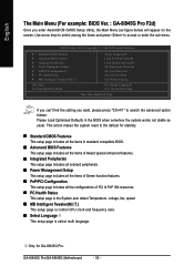
...'t find the setting you enter Award BIOS CMOS Setup Utility, the Main Menu (as usual. GA-8I945G Pro/GA-8I945G Motherboard - 30 - English The Main Menu (For example: BIOS Ver. : GA-8I945G Pro F2d) Once you want, please press "Ctrl+F1" to the default for GA-8I945G Pro. CMOS Setup Utility-Copyright (C) 1984-2005 Award Software ` Standard CMOS Features ` Advanced BIOS Features...
...'t find the setting you enter Award BIOS CMOS Setup Utility, the Main Menu (as usual. GA-8I945G Pro/GA-8I945G Motherboard - 30 - English The Main Menu (For example: BIOS Ver. : GA-8I945G Pro F2d) Once you want, please press "Ctrl+F1" to the default for GA-8I945G Pro. CMOS Setup Utility-Copyright (C) 1984-2005 Award Software ` Standard CMOS Features ` Advanced BIOS Features...
Manual
Page 32
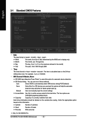
... Dec. IDE Channel 0 Master, Slave IDE HDD Auto-Detection Press "Enter" to automatically detect IDE devices during POST(default) None Select this option for GA-8I945G Pro. IDE Device Setup. GA-8I945G Pro/GA-8I945G Motherboard - 32 - Week Month The week, from 1999 through 2098 Time The times format in . The time is , , , . Manual User can use one of...
... Dec. IDE Channel 0 Master, Slave IDE HDD Auto-Detection Press "Enter" to automatically detect IDE devices during POST(default) None Select this option for GA-8I945G Pro. IDE Device Setup. GA-8I945G Pro/GA-8I945G Motherboard - 32 - Week Month The week, from 1999 through 2098 Time The times format in . The time is , , , . Manual User can use one of...
Manual
Page 34
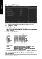
Hard Disk Boot Priority Select boot sequence for GA-8I945G Pro. Use < > or < > to select a device, then press to move it up, or to exit this function. Press to move it down the list. USB-CDROM ... will show up when you install the Intel® Pentium® 4 processor with HT Technology. Only for onboard(or add-on cards) SCSI, RAID, etc. GA-8I945G Pro/GA-8I945G Motherboard - 34 - to 3 No-Execute Memory Protect (Note) CPU Enhanced Halt (C1E) (Note) CPU Thermal Monitor 2(TM2) (Note) CPU EIST Function (Note) On-Chip Frame Buffer...
Hard Disk Boot Priority Select boot sequence for GA-8I945G Pro. Use < > or < > to select a device, then press to move it up, or to exit this function. Press to move it down the list. USB-CDROM ... will show up when you install the Intel® Pentium® 4 processor with HT Technology. Only for onboard(or add-on cards) SCSI, RAID, etc. GA-8I945G Pro/GA-8I945G Motherboard - 34 - to 3 No-Execute Memory Protect (Note) CPU Enhanced Halt (C1E) (Note) CPU Thermal Monitor 2(TM2) (Note) CPU EIST Function (Note) On-Chip Frame Buffer...

Manual
Page 36
GA-8I945G Pro/GA-8I945G Motherboard - 36 - Only for GA-8I945G Pro. English 2-3 Integrated Peripherals CMOS Setup Utility-Copyright (C) 1984-2005 Award Software Integrated Peripherals On-Chip Primary PCI IDE On-Chip Secondard PCI IDE SATA RAID/...
GA-8I945G Pro/GA-8I945G Motherboard - 36 - Only for GA-8I945G Pro. English 2-3 Integrated Peripherals CMOS Setup Utility-Copyright (C) 1984-2005 Award Software Integrated Peripherals On-Chip Primary PCI IDE On-Chip Secondard PCI IDE SATA RAID/...

Manual
Page 37
...Set the onboard SATA controller to RAID mode. (Default value) AHCI Disabled Set the onboard SATA controller to 4 HDDs on the motherboard; 2 for SATA and the other for GA-8I945G Pro. - 37 - SATA Port 0/2 Set to This value will auto detect. (Default value) Combined Enhanced Set On-Chip SATA...6 HDDs to enable advanced Serial ATA features such as Native Command Queuing and hot plug. Set On-Chip SATA mode to Enhanced, the motherboard allows up to AHCI mode. USB Controller Enabled Disabled Enable USB Controller. (Default value) Disable USB Controller. For more details about AHCI...
...Set the onboard SATA controller to RAID mode. (Default value) AHCI Disabled Set the onboard SATA controller to 4 HDDs on the motherboard; 2 for SATA and the other for GA-8I945G Pro. - 37 - SATA Port 0/2 Set to This value will auto detect. (Default value) Combined Enhanced Set On-Chip SATA...6 HDDs to enable advanced Serial ATA features such as Native Command Queuing and hot plug. Set On-Chip SATA mode to Enhanced, the motherboard allows up to AHCI mode. USB Controller Enabled Disabled Enable USB Controller. (Default value) Disable USB Controller. For more details about AHCI...
Manual
Page 38
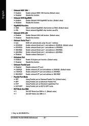
... Disabled Disable onboard Serial port 1. Using Parallel port as RAID. (Default value) ATA Select onboard GigaRAID chip function asa ATA. GA-8I945G Pro/GA-8I945G Motherboard - 38 - Enable onboard Serial port 1 and address is 3F8/IRQ4. (Default value) 2F8/IRQ3 Enable onboard Serial port 1...port as Standard Parallel Port. (Default value) EPP ECP ECP+EPP Using Parallel port as Extended Capabilities Port. Only for GA-8I945G Pro. English Onboard H/W 1394 Enabled Enable onboard IEEE 1394 function.(Default value) Disabled Disable this function. Onboard H/W GigaRAID Enabled ...
... Disabled Disable onboard Serial port 1. Using Parallel port as RAID. (Default value) ATA Select onboard GigaRAID chip function asa ATA. GA-8I945G Pro/GA-8I945G Motherboard - 38 - Enable onboard Serial port 1 and address is 3F8/IRQ4. (Default value) 2F8/IRQ3 Enable onboard Serial port 1...port as Standard Parallel Port. (Default value) EPP ECP ECP+EPP Using Parallel port as Extended Capabilities Port. Only for GA-8I945G Pro. English Onboard H/W 1394 Enabled Enable onboard IEEE 1394 function.(Default value) Disabled Disable this function. Onboard H/W GigaRAID Enabled ...


