Manual
Page 1
GA-8I945G Pro/ GA-8I945G Intel® Pentium® D / Pentium® 4 LGA775 Processor Motherboard User's Manual Rev. 1005 12ME-8I945GP-1005 * The WEEE marking on the product indicates this product must not be disposed of with user's other household waste and must be handed over to a designated collection point for the recycling of waste electrical and electronic equipment!! * The WEEE marking applies only in European Union's member states.
GA-8I945G Pro/ GA-8I945G Intel® Pentium® D / Pentium® 4 LGA775 Processor Motherboard User's Manual Rev. 1005 12ME-8I945GP-1005 * The WEEE marking on the product indicates this product must not be disposed of with user's other household waste and must be handed over to a designated collection point for the recycling of waste electrical and electronic equipment!! * The WEEE marking applies only in European Union's member states.

Manual
Page 4
Table of Contents GA-8I945G Pro Motherboard Layout 6 GA-8I945G Motherboard Layout 7 Block Diagram ...8 Chapter 1 Hardware Installation 9 1-1 Considerations Prior to Installation 9 1-2 Feature Summary 10 1-3 Installation of the CPU and ... of Expansion Cards 16 1-7 I/O Back Panel Introduction 17 1-8 Connectors Introduction 18 Chapter 2 BIOS Setup 29 The Main Menu (For example: BIOS Ver. : GA-8I945G Pro F2d 30 2-1 Standard CMOS Features 32 2-2 Advanced BIOS Features 34 2-3 IntegratedPeripherals 36 2-4 Power Management Setup 39 2-5 PnP/PCI Configurations 41 2-6 PC Health Status...
Table of Contents GA-8I945G Pro Motherboard Layout 6 GA-8I945G Motherboard Layout 7 Block Diagram ...8 Chapter 1 Hardware Installation 9 1-1 Considerations Prior to Installation 9 1-2 Feature Summary 10 1-3 Installation of the CPU and ... of Expansion Cards 16 1-7 I/O Back Panel Introduction 17 1-8 Connectors Introduction 18 Chapter 2 BIOS Setup 29 The Main Menu (For example: BIOS Ver. : GA-8I945G Pro F2d 30 2-1 Standard CMOS Features 32 2-2 Advanced BIOS Features 34 2-3 IntegratedPeripherals 36 2-4 Power Management Setup 39 2-5 PnP/PCI Configurations 41 2-6 PC Health Status...
Manual
Page 5
Chapter 3 Install Drivers 51 3-1 Install Chipset Drivers 51 3-2 SoftwareApplications 52 3-3 Driver CD Information 52 3-4 Hardware Information 53 3-5 Contact Us ...53 Chapter 4 Appendix 55 4-1 Unique Software Utilities 55 4-1-1 EasyTune 5 Introduction 56 4-1-2 Xpress Recovery2 Introduction 57 4-1-3 Flash BIOS Method Introduction 59 4-1-4 Serial ATA BIOS Setting Utility Introduction 70 4-1-5 2- / 4- / 6- / 8- Channel Audio Function Introduction 77 4-2 Troubleshooting 81 Only for GA-8I945G Pro. - 5 -
Chapter 3 Install Drivers 51 3-1 Install Chipset Drivers 51 3-2 SoftwareApplications 52 3-3 Driver CD Information 52 3-4 Hardware Information 53 3-5 Contact Us ...53 Chapter 4 Appendix 55 4-1 Unique Software Utilities 55 4-1-1 EasyTune 5 Introduction 56 4-1-2 Xpress Recovery2 Introduction 57 4-1-3 Flash BIOS Method Introduction 59 4-1-4 Serial ATA BIOS Setting Utility Introduction 70 4-1-5 2- / 4- / 6- / 8- Channel Audio Function Introduction 77 4-2 Troubleshooting 81 Only for GA-8I945G Pro. - 5 -

Manual
Page 6
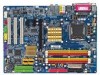
GA-8I945G Pro Motherboard Layout KB_MS ATX_12V CPU_FAN COAXIAL LGA775 ATX OPTICAL PWR_FAN LPT LAN VGA GA-8I945G Pro R_USB USB FDD AUDIO1 AUDIO2 F_AUDIO Intel 945G Broadcom 5789 CD_IN CODEC IT8712 NB_FAN PCIE_16 PCIE_1 PCIE_2 Main BIOS Back BIOS ICH7R PCI1 TSB82AA2 PCI2 SATAII0 IT8212 SATAII1 DDRII1 DDRII2 SATAII2 SATAII3 DDRII3 DDRII4 IDE1 IDE3 IDE2 SYS_FAN COMA CI RF_ID SPDIF_I PCI3 TSB81BA3 BAT F_USB GREEN_USB F1_1394 F2_1394 F_PANEL PWR_LED (Optional) CLR_CMOS - 6 -
GA-8I945G Pro Motherboard Layout KB_MS ATX_12V CPU_FAN COAXIAL LGA775 ATX OPTICAL PWR_FAN LPT LAN VGA GA-8I945G Pro R_USB USB FDD AUDIO1 AUDIO2 F_AUDIO Intel 945G Broadcom 5789 CD_IN CODEC IT8712 NB_FAN PCIE_16 PCIE_1 PCIE_2 Main BIOS Back BIOS ICH7R PCI1 TSB82AA2 PCI2 SATAII0 IT8212 SATAII1 DDRII1 DDRII2 SATAII2 SATAII3 DDRII3 DDRII4 IDE1 IDE3 IDE2 SYS_FAN COMA CI RF_ID SPDIF_I PCI3 TSB81BA3 BAT F_USB GREEN_USB F1_1394 F2_1394 F_PANEL PWR_LED (Optional) CLR_CMOS - 6 -
Manual
Page 8
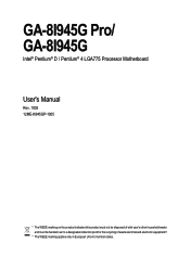
Only for GA-8I945G Pro. Only for GA-8I945G. - 8 - Block Diagram PCI-ECLK (100MHz) VGA PCI Express x16 2 PCI Express x1 RJ45 PCI-ECLK (100MHz) Broadcom 5789 x1 x1 x 1 PCI Express Bus PCI Bus ...
Only for GA-8I945G Pro. Only for GA-8I945G. - 8 - Block Diagram PCI-ECLK (100MHz) VGA PCI Express x16 2 PCI Express x1 RJ45 PCI-ECLK (100MHz) Broadcom 5789 x1 x1 x 1 PCI Express Bus PCI Bus ...

Manual
Page 10
...10/100/1000 Mbit) 1 RJ 45 port Supported on the Win 2000/XP operating systems (Note 1) For further CPU support information, please go to GIGABYTE's website. (Note 2) Due to 4GB memory) (Note 2) Supports 1.8V DDR II DIMM Supports dual channel DDR II 667(Note 3)/533/400 DIMM... connection of memory is reserved for system usage and therefore the actual memory size is less than the stated amount. Only for GA-8I945G. GA-8I945G Pro/GA-8I945G Motherboard - 10 - Only for GA-8I945G Pro. For example, 4 GB of memory size will instead be shown as 3.xxGB memory during system startup. (Note 3) To ...
...10/100/1000 Mbit) 1 RJ 45 port Supported on the Win 2000/XP operating systems (Note 1) For further CPU support information, please go to GIGABYTE's website. (Note 2) Due to 4GB memory) (Note 2) Supports 1.8V DDR II DIMM Supports dual channel DDR II 667(Note 3)/533/400 DIMM... connection of memory is reserved for system usage and therefore the actual memory size is less than the stated amount. Only for GA-8I945G. GA-8I945G Pro/GA-8I945G Motherboard - 10 - Only for GA-8I945G Pro. For example, 4 GB of memory size will instead be shown as 3.xxGB memory during system startup. (Note 3) To ...
Manual
Page 11
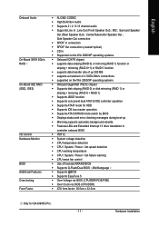
...; Over Voltage via BIOS (CPU/DDR/PCIE/FSB) Š Over Clock via BIOS (CPU/DDR) Š ATX form factor; 30.5cm x 22.0cm Only for GA-8I945G Pro. - 11 - Hardware Installation Center/Subwoofer Speaker Out ; English Onboard Audio On-Board SATA 3Gb/s RAID On-Board IDE RAID (IDE2, IDE3) I/O Control Hardware Monitor BIOS...
...; Over Voltage via BIOS (CPU/DDR/PCIE/FSB) Š Over Clock via BIOS (CPU/DDR) Š ATX form factor; 30.5cm x 22.0cm Only for GA-8I945G Pro. - 11 - Hardware Installation Center/Subwoofer Speaker Out ; English Onboard Audio On-Board SATA 3Gb/s RAID On-Board IDE RAID (IDE2, IDE3) I/O Control Hardware Monitor BIOS...

Manual
Page 12
... to your computer system requires all of the CPU socket. Please make sure that supports HT Technology - If you wish to the CPU during installation.) GA-8I945G Pro/GA-8I945G Motherboard - 12 - Please set the frequency beyond hardware specifications since it does not meet the required standards for the peripherals. CPU: An Intel® Pentium...
... to your computer system requires all of the CPU socket. Please make sure that supports HT Technology - If you wish to the CPU during installation.) GA-8I945G Pro/GA-8I945G Motherboard - 12 - Please set the frequency beyond hardware specifications since it does not meet the required standards for the peripherals. CPU: An Intel® Pentium...
Manual
Page 14
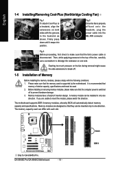
...damage. 3. Memory modules have a foolproof insertion design. Memory modules are unable to insert the module, please switch the direction. GA-8I945G Pro/GA-8I945G Motherboard - 14 - A memory module can be used is properly affixed onto the heatsink, plug the power cable into position.... The motherboard supports DDR II memory modules, whereby BIOS will automatically detect memory capacity and specifications. Only for GA-8I945G Pro. English 1-4 Installing/Removing Cool-Plus (Northbridge Cooling Fan) Fig.1 To attach Cool-Plus to a heatsink, align the ...
...damage. 3. Memory modules have a foolproof insertion design. Memory modules are unable to insert the module, please switch the direction. GA-8I945G Pro/GA-8I945G Motherboard - 14 - A memory module can be used is properly affixed onto the heatsink, plug the power cable into position.... The motherboard supports DDR II memory modules, whereby BIOS will automatically detect memory capacity and specifications. Only for GA-8I945G Pro. English 1-4 Installing/Removing Cool-Plus (Northbridge Cooling Fan) Fig.1 To attach Cool-Plus to a heatsink, align the ...
Manual
Page 15
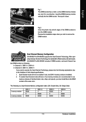
... of Intel chipset specifications. 1. The following explanations due to operate the Dual Channel Technology, please note the following is installed. 2. Hardware Installation GA-8I945G Pro/GA-8I945G includes 4 DIMM sockets, and each Channel has two DIMM sockets as following: Channel A : DDR II 1, DDR II 2 Channel B :...you want to the limitation of Memory Bus will not be enabled if only one direction. Dual Channel Memory Configuration GA-8I945G Pro/GA-8I945G supports the Dual Channel Technology. Then push it is recommended to use memory modules of the DIMM sockets to remove ...
... of Intel chipset specifications. 1. The following explanations due to operate the Dual Channel Technology, please note the following is installed. 2. Hardware Installation GA-8I945G Pro/GA-8I945G includes 4 DIMM sockets, and each Channel has two DIMM sockets as following: Channel A : DDR II 1, DDR II 2 Channel B :...you want to the limitation of Memory Bus will not be enabled if only one direction. Dual Channel Memory Configuration GA-8I945G Pro/GA-8I945G supports the Dual Channel Technology. Then push it is recommended to use memory modules of the DIMM sockets to remove ...

Manual
Page 16
... contacts on the computer, if necessary, setup BIOS utility of the expansion card. 6. Replace your VGA card is locked by following the steps outlined below: 1. GA-8I945G Pro/GA-8I945G Motherboard - 16 - Power on the card are indeed seated in motherboard. 4. Installing a PCI Express x 16 expansion card: Please align the VGA card to release the...
... contacts on the computer, if necessary, setup BIOS utility of the expansion card. 6. Replace your VGA card is locked by following the steps outlined below: 1. GA-8I945G Pro/GA-8I945G Motherboard - 16 - Power on the card are indeed seated in motherboard. 4. Installing a PCI Express x 16 expansion card: Please align the VGA card to release the...

Manual
Page 18
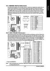
GA-8I945G Pro/GA-8I945G Motherboard - 18 - channel audio setup steps for detailed software configuration information. 1-8 Connectors Introduction 1 3 2 5 7 6 8 10 9 8 13 14 4 19 20 18 17 15 15 16 21 11 ... 17) COMA 7) FDD 18) RF_ID 8) IDE1 / IDE2 / IDE3 19) CI 9) SATAII0 / SATAII1 / SATAII2 / SATAII3 20) CLR_CMOS 10) F_AUDIO 21) BAT 11) PWR_LED (Optional) Only for GA-8I945G Pro. Only microphones still MUST be connected to the default Mic In jack ( ) . Surround side speakers can be connected to Side Speaker Out jack. Side Speaker...
GA-8I945G Pro/GA-8I945G Motherboard - 18 - channel audio setup steps for detailed software configuration information. 1-8 Connectors Introduction 1 3 2 5 7 6 8 10 9 8 13 14 4 19 20 18 17 15 15 16 21 11 ... 17) COMA 7) FDD 18) RF_ID 8) IDE1 / IDE2 / IDE3 19) CI 9) SATAII0 / SATAII1 / SATAII2 / SATAII3 20) CLR_CMOS 10) F_AUDIO 21) BAT 11) PWR_LED (Optional) Only for GA-8I945G Pro. Only microphones still MUST be connected to the default Mic In jack ( ) . Surround side speakers can be connected to Side Speaker Out jack. Side Speaker...

Manual
Page 20
...prevent CPU overheating and failure. 1 CPU_FAN 1 SYS_FAN/ PWR_FAN Pin No. 1 2 3 4 Definition GND +12V Sense Speed Control (Only for GA-8I945G Pro. Definition 1 +12V 2 GND 1 Only for CPU_FAN) 6) NB_FAN (Chip Fan Connector) If you installed wrong direction, the chip fan will damage... connector wire is GND) Pin No. Please remember to connect the power to the CPU fan to prevent system overheating and failure. GA-8I945G Pro/GA-8I945G Motherboard - 20 - English 3/4/5) CPU_FAN / SYS_FAN / PWR_FAN (Cooler Fan Power Connector) The cooler fan power connector supplies a +12V...
...prevent CPU overheating and failure. 1 CPU_FAN 1 SYS_FAN/ PWR_FAN Pin No. 1 2 3 4 Definition GND +12V Sense Speed Control (Only for GA-8I945G Pro. Definition 1 +12V 2 GND 1 Only for CPU_FAN) 6) NB_FAN (Chip Fan Connector) If you installed wrong direction, the chip fan will damage... connector wire is GND) Pin No. Please remember to connect the power to the CPU fan to prevent system overheating and failure. GA-8I945G Pro/GA-8I945G Motherboard - 20 - English 3/4/5) CPU_FAN / SYS_FAN / PWR_FAN (Cooler Fan Power Connector) The cooler fan power connector supplies a +12V...

Manual
Page 22
... FSENSE2 AC'97 Audio: Pin No. Incorrect connection between the module and connector will make the audio device unable to work or even damage it. GA-8I945G Pro/GA-8I945G Motherboard - 22 - Check the pin assignments carefully while you wish to use the front audio function, connect the front panel audio module to the instructions...
... FSENSE2 AC'97 Audio: Pin No. Incorrect connection between the module and connector will make the audio device unable to work or even damage it. GA-8I945G Pro/GA-8I945G Motherboard - 22 - Check the pin assignments carefully while you wish to use the front audio function, connect the front panel audio module to the instructions...

Manual
Page 24
For optional SPDIF cable, please contact your device has digital output function. Definition 1 Power 1 2 SPDIFI 3 GND GA-8I945G Pro/GA-8I945G Motherboard - 24 - English 13) CD_IN (CD IN) Connect CD-ROM or DVD-ROM audio out to work or even damage it. Be careful with the ...
For optional SPDIF cable, please contact your device has digital output function. Definition 1 Power 1 2 SPDIFI 3 GND GA-8I945G Pro/GA-8I945G Motherboard - 24 - English 13) CD_IN (CD IN) Connect CD-ROM or DVD-ROM audio out to work or even damage it. Be careful with the ...
Manual
Page 25
Users who wish to wake up from S3 mode. GA-8I945G Pro 2 10 1 9 GA-8I945G 2 10 1 9 Pin No. 1 2 3 4 5 6 7 8 9 10 Definition Power Power USB DXUSB DyUSB DX+ USB Dy+ GND GND No Pin NC 16) F1_1394/F2_1394 (IEEE 1394 Connector) Serial ... this connector via the optional front USB cable. The GREEN_USB connector provides no standby power when system is shut down the standby power(note) for GA-8I945G Pro. 2 F2_1394 1 F1_1394 2 1 Pin No. 1 2 3 4 5 6 7 8 9 10 16 15 10 9 Definition TPA2+ TPA2GND GND TPB2+ TPB2No Pin Power Power GND Pin No. 1 2 3 4 5 6 7 8 9 10 11 12 13 14...
Users who wish to wake up from S3 mode. GA-8I945G Pro 2 10 1 9 GA-8I945G 2 10 1 9 Pin No. 1 2 3 4 5 6 7 8 9 10 Definition Power Power USB DXUSB DyUSB DX+ USB Dy+ GND GND No Pin NC 16) F1_1394/F2_1394 (IEEE 1394 Connector) Serial ... this connector via the optional front USB cable. The GREEN_USB connector provides no standby power when system is shut down the standby power(note) for GA-8I945G Pro. 2 F2_1394 1 F1_1394 2 1 Pin No. 1 2 3 4 5 6 7 8 9 10 16 15 10 9 Definition TPA2+ TPA2GND GND TPB2+ TPB2No Pin Power Power GND Pin No. 1 2 3 4 5 6 7 8 9 10 11 12 13 14...

Manual
Page 26
Check the pin assignments before you to connect external devices to use extra function. Definition 1 Power 2 RFID_RI- 1 3 RF_TXD 4 RF_RXD 5 NC 6 GND GA-8I945G Pro/GA-8I945G Motherboard - 26 - Please contact your nearest dealer for optional COMA cable. 2 10 1 9 Pin No. 1 2 3 4 5 6 7 8 9 10 Definition NDCDANSINA NSOUTA NDTRAGND ... the pin assignments while you connect the COMA cable. Pin No. Please contact your nearest dealer for the optional GIGABYTE external device. English 17) COMA (COMA Connector) Be careful with the polarity of the COMB connector.
Check the pin assignments before you to connect external devices to use extra function. Definition 1 Power 2 RFID_RI- 1 3 RF_TXD 4 RF_RXD 5 NC 6 GND GA-8I945G Pro/GA-8I945G Motherboard - 26 - Please contact your nearest dealer for optional COMA cable. 2 10 1 9 Pin No. 1 2 3 4 5 6 7 8 9 10 Definition NDCDANSINA NSOUTA NDTRAGND ... the pin assignments while you connect the COMA cable. Pin No. Please contact your nearest dealer for the optional GIGABYTE external device. English 17) COMA (COMA Connector) Be careful with the polarity of the COMB connector.

Manual
Page 28
... power cord. 2. Re-install the battery. 4. Take out the battery gently and put it aside for about 10 minutes (Or you want to erase CMOS... 1. GA-8I945G Pro/GA-8I945G Motherboard - 28 - Dispose of explosion if battery is incorrectly replaced. Plug the power cord and turn ON the computer. Replace only with the same or...
... power cord. 2. Re-install the battery. 4. Take out the battery gently and put it aside for about 10 minutes (Or you want to erase CMOS... 1. GA-8I945G Pro/GA-8I945G Motherboard - 28 - Dispose of explosion if battery is incorrectly replaced. Plug the power cord and turn ON the computer. Replace only with the same or...
Manual
Page 30
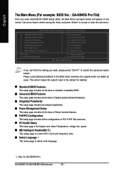
...... This action makes the system reset to accept or enter the sub-menu. GA-8I945G Pro/GA-8I945G Motherboard - 30 - Use arrow keys to select among the items and press to the default for GA-8I945G Pro. English The Main Menu (For example: BIOS Ver. : GA-8I945G Pro F2d) Once you want, please press "Ctrl+F1" to search the advanced option...
...... This action makes the system reset to accept or enter the sub-menu. GA-8I945G Pro/GA-8I945G Motherboard - 30 - Use arrow keys to select among the items and press to the default for GA-8I945G Pro. English The Main Menu (For example: BIOS Ver. : GA-8I945G Pro F2d) Once you want, please press "Ctrl+F1" to search the advanced option...
Manual
Page 32
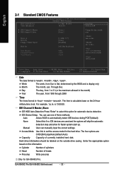
... 1999 through 2098 Time The times format in the month) 1999 to select this information. Hard drive information should be labeled on this option for GA-8I945G Pro. Week Month The week, from 1 to automatically detect IDE devices during POST(default) None Select this to Sat, determined by the BIOS and is , , , . IDE... device detection. to Sat. is calculated base on the 24-hour military-time clock. Cylinder Number of cylinders Head Number of currently installed hard disk. GA-8I945G Pro/GA-8I945G Motherboard - 32 -
... 1999 through 2098 Time The times format in the month) 1999 to select this information. Hard drive information should be labeled on this option for GA-8I945G Pro. Week Month The week, from 1 to automatically detect IDE devices during POST(default) None Select this to Sat, determined by the BIOS and is , , , . IDE... device detection. to Sat. is calculated base on the 24-hour military-time clock. Cylinder Number of cylinders Head Number of currently installed hard disk. GA-8I945G Pro/GA-8I945G Motherboard - 32 -
