Manual
Page 1
Table of Contents Configuring IDE RAID Hard Drive(s) (Controller GigaRAID (IT8212 2 (1) Installing IDE hard drive(s) in your system 2 (2) Configuring GigaRAID controller mode and boot sequence in BIOS Setup 3 (3) Configuring RAID set in RAID BIOS 5 (4) Making a IDE RAID controller driver disk 14 (5) Installing IDE RAID controller driver during OS installation 16
Table of Contents Configuring IDE RAID Hard Drive(s) (Controller GigaRAID (IT8212 2 (1) Installing IDE hard drive(s) in your system 2 (2) Configuring GigaRAID controller mode and boot sequence in BIOS Setup 3 (3) Configuring RAID set in RAID BIOS 5 (4) Making a IDE RAID controller driver disk 14 (5) Installing IDE RAID controller driver during OS installation 16
Manual
Page 2
...drive. (b) An empty formatted floppy disk. (c) Windows XP/2000 setup disk. (d) Driver CD for your motherboard. (1) Installing IDE hard drive(s) in RAID BIOS. (4) Make a floppy disk containing the IDE RAID controller driver (5) Install the IDE RAID controller driver during OS installation. Ác Configuring IDE RAID Hard ...follow the steps below ¤å (1) Install IDE hard drive(s) in your computer. (2) Configure GigaRAID controller mode and boot sequence in BIOS Setup. (3)* Configure RAID set in your system Attach one end of the IDE cable to the rear of the IDE hard drive and ...
...drive. (b) An empty formatted floppy disk. (c) Windows XP/2000 setup disk. (d) Driver CD for your motherboard. (1) Installing IDE hard drive(s) in RAID BIOS. (4) Make a floppy disk containing the IDE RAID controller driver (5) Install the IDE RAID controller driver during OS installation. Ác Configuring IDE RAID Hard ...follow the steps below ¤å (1) Install IDE hard drive(s) in your computer. (2) Configure GigaRAID controller mode and boot sequence in BIOS Setup. (3)* Configure RAID set in your system Attach one end of the IDE cable to the rear of the IDE hard drive and ...
Manual
Page 3
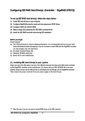
...for your computer and press Del to make sure whether the GigaRAID controller are configured correctly in system BIOS Setup and set GigaRAID Function to RAID (Figure 1). If you have to enter BIOS Setup during POST (Power-On Self Test). CMOS Setup Utility-Copyright (C) 1984-2004 Award Software ... F5: Previous Values +/-/PU/PD: Value F10: Save F6: Fail-Safe Defaults Figure 1 ESC: Exit F1: General Help F7: Optimized Defaults The BIOS Setup menus described in this section may not show the exact settings for the IDE RAID hard drive(s). Step 1: Turn on the motherboard you do...
...for your computer and press Del to make sure whether the GigaRAID controller are configured correctly in system BIOS Setup and set GigaRAID Function to RAID (Figure 1). If you have to enter BIOS Setup during POST (Power-On Self Test). CMOS Setup Utility-Copyright (C) 1984-2004 Award Software ... F5: Previous Values +/-/PU/PD: Value F10: Save F6: Fail-Safe Defaults Figure 1 ESC: Exit F1: General Help F7: Optimized Defaults The BIOS Setup menus described in this section may not show the exact settings for the IDE RAID hard drive(s). Step 1: Turn on the motherboard you do...
Manual
Page 4
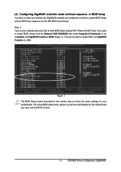
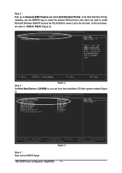
...2). ¤å CMOS Setup Utility-Copyright (C) 1984-2004 Award Software Hard Disk Boot Priority Step 3 Figure 2 Set First Boot Device to Advanced BIOS Features and select Hard Disk Boot Priority. IDE RAID Drives Configuration (GigaRAID) - 4 - In the Hard Disk Boot Priority Åé submenu, ...hard drive onto which you can boot from Installation CD after system restarts.(Figure 3) CMOS Setup Utility-Copyright (C) 1984-2004 Award Software Advanced BIOS Features : Move Enter: Select F5: Previous Values +/-/PU/PD: Value F10: Save F6: Fail-Safe Defaults Figure 3 ESC: Exit F1...
...2). ¤å CMOS Setup Utility-Copyright (C) 1984-2004 Award Software Hard Disk Boot Priority Step 3 Figure 2 Set First Boot Device to Advanced BIOS Features and select Hard Disk Boot Priority. IDE RAID Drives Configuration (GigaRAID) - 4 - In the Hard Disk Boot Priority Åé submenu, ...hard drive onto which you can boot from Installation CD after system restarts.(Figure 3) CMOS Setup Utility-Copyright (C) 1984-2004 Award Software Advanced BIOS Features : Move Enter: Select F5: Previous Values +/-/PU/PD: Value F10: Save F6: Fail-Safe Defaults Figure 3 ESC: Exit F1...
Manual
Page 5
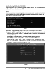
...to the GigaRAID controller correctly, after the Power-On Self Test (POST) memory test begins and before the operating system boot begins, the GigaRAID BIOS will guide you to set an array and this step and proceed to Section 4 if you do not want to create RAID. Navigate the ...RAID set on the GigaRAID controller. Auto Configuration [1]: It will detect the drives attached and show the following screen. (3) Configuring RAID set in RAID BIOS Enter the RAID setup utility to select the item you need. IDE RAID Drives Configuration (GigaRAID) Skip this is the simplest and fastest way to...
...to the GigaRAID controller correctly, after the Power-On Self Test (POST) memory test begins and before the operating system boot begins, the GigaRAID BIOS will guide you to set an array and this step and proceed to Section 4 if you do not want to create RAID. Navigate the ...RAID set on the GigaRAID controller. Auto Configuration [1]: It will detect the drives attached and show the following screen. (3) Configuring RAID set in RAID BIOS Enter the RAID setup utility to select the item you need. IDE RAID Drives Configuration (GigaRAID) Skip this is the simplest and fastest way to...
Manual
Page 16
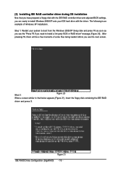
..., there will be a few moments of Windows XP installation. ¤å Step 1: Restart your IDE hard drive with the IDE RAID controller driver and adjusted BIOS settings, you need to that you have prepared a floppy disk with the driver. Figure 21 IDE RAID Drives Configuration (GigaRAID) - 16 - Step 2: Figure 20 When...
..., there will be a few moments of Windows XP installation. ¤å Step 1: Restart your IDE hard drive with the IDE RAID controller driver and adjusted BIOS settings, you need to that you have prepared a floppy disk with the driver. Figure 21 IDE RAID Drives Configuration (GigaRAID) - 16 - Step 2: Figure 20 When...
Manual
Page 9
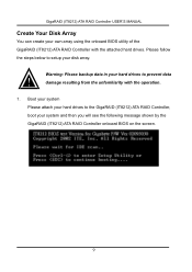
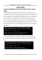
... GigaRAID (IT8212) ATA RAID Controller, boot your system and then you will see the following message shown by the GigaRAID (IT8212) ATA RAID Controller onboard BIOS on the screen. 9 Please follow the steps below to setup your disk array. GigaRAID (IT8212) ATA RAID Controller USER'S MANUAL Create Your Disk Array You...
... GigaRAID (IT8212) ATA RAID Controller, boot your system and then you will see the following message shown by the GigaRAID (IT8212) ATA RAID Controller onboard BIOS on the screen. 9 Please follow the steps below to setup your disk array. GigaRAID (IT8212) ATA RAID Controller USER'S MANUAL Create Your Disk Array You...
Manual
Page 10
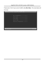
The screen below will be shown. 10 GigaRAID (IT8212) ATA RAID Controller USER'S MANUAL Please press "Ctrl-G" keys to enter the BIOS utility Main Menu.
The screen below will be shown. 10 GigaRAID (IT8212) ATA RAID Controller USER'S MANUAL Please press "Ctrl-G" keys to enter the BIOS utility Main Menu.
Manual
Page 14
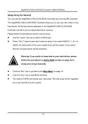
follow the procedures below to set an array: Use the "space" bar key to quit BIOS and boot. Click the "Esc" key to go back to act as independent drive volumes. You need to use the GigaRAID (IT8212) ATA RAID Controller ...
follow the procedures below to set an array: Use the "space" bar key to quit BIOS and boot. Click the "Esc" key to go back to act as independent drive volumes. You need to use the GigaRAID (IT8212) ATA RAID Controller ...
Manual
Page 15
If your array's configuration is incorrect, you will see the following message shown by the GigaRAID (IT8212) ATA RAID Controller onboard BIOS on your screen. It also provides the information of each hard drive and the configuration of the GigaRAID (IT8212) ATA RAID Controller. You can press "...
If your array's configuration is incorrect, you will see the following message shown by the GigaRAID (IT8212) ATA RAID Controller onboard BIOS on your screen. It also provides the information of each hard drive and the configuration of the GigaRAID (IT8212) ATA RAID Controller. You can press "...
Manual
Page 88
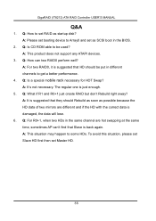
Q: How to set RAID as SCSI boot in the BIOS. 2. Q: Is a special mobile rack necessary for HOT Swap? A: It's not necessary. A: This situation may happen to Array0 and set Master HD. 88 A: This product does ...
Q: How to set RAID as SCSI boot in the BIOS. 2. Q: Is a special mobile rack necessary for HOT Swap? A: It's not necessary. A: This situation may happen to Array0 and set Master HD. 88 A: This product does ...

Manual
Page 4
...GA-8I915P (Ultra)(Pro)(-G) Motherboard Layout 6 Block Diagram ...7 Chapter 1 Hardware Installation 9 1-1 Considerations Priorto Installation 9 1-2 Feature Summary 10 1-3 Installation of the CPU and Heatsink 12 1-3-1 Installation of the CPU 12 1-3-2 Installation of the Heatsink 13 1-4 Installation of Memory 14 1-5 Installexpansion cards 16 1-6 I/O Back Panel Introduction 17 1-7 ConnectorsIntroduction 18 Chapter 2 BIOS... Setup 29 The Main Menu (For example: BIOS Ver. : F1 30 2-1 Standard CMOS Features 32 2-2 Advanced BIOS Features 34 2-3 IntegratedPeripherals...
...GA-8I915P (Ultra)(Pro)(-G) Motherboard Layout 6 Block Diagram ...7 Chapter 1 Hardware Installation 9 1-1 Considerations Priorto Installation 9 1-2 Feature Summary 10 1-3 Installation of the CPU and Heatsink 12 1-3-1 Installation of the CPU 12 1-3-2 Installation of the Heatsink 13 1-4 Installation of Memory 14 1-5 Installexpansion cards 16 1-6 I/O Back Panel Introduction 17 1-7 ConnectorsIntroduction 18 Chapter 2 BIOS... Setup 29 The Main Menu (For example: BIOS Ver. : F1 30 2-1 Standard CMOS Features 32 2-2 Advanced BIOS Features 34 2-3 IntegratedPeripherals...

Manual
Page 5
Chapter 3 Install Drivers 49 3-1 Install Chipset Drivers 49 3-2 SoftwareApplications 50 3-3 Driver CD Information 50 3-4 Hardware Information 51 3-5 Contact Us ...51 Chapter 4 Appendix 53 4-1 Unique Software Utilities 53 4-1-1 Xpress Recovery Introduction 54 4-1-2 Flash BIOS Method Introduction 57 4-1-3 2 / 4 / 5.1 / 7.1 Channel Audio Function Introduction 68 4-2 Troubleshooting ...74 - 5 -
Chapter 3 Install Drivers 49 3-1 Install Chipset Drivers 49 3-2 SoftwareApplications 50 3-3 Driver CD Information 50 3-4 Hardware Information 51 3-5 Contact Us ...51 Chapter 4 Appendix 53 4-1 Unique Software Utilities 53 4-1-1 Xpress Recovery Introduction 54 4-1-2 Flash BIOS Method Introduction 57 4-1-3 2 / 4 / 5.1 / 7.1 Channel Audio Function Introduction 68 4-2 Troubleshooting ...74 - 5 -

Manual
Page 6
... SP DIF_IN C PU _ FAN A TX_12V PWR_FA N LGA 775 GA-8I915P (Ultra)(Pro)(-G) DDR1 DDR2 DDR3 DDR4 ATX LPT COMA USB LAN USB IT8212 CLR_CMOS A U D IO 1 A U D IO 2 Marv ell 8001 I ntel 915P AZALIA_FP CD_IN C ODEC N B_ FAN P CI E_1 P CI E_2 BAC K BIOS P CI E_3 MAIN BIOS P CI E _16 BAT I ntel I CH 6 S_AT A4 S_AT...
... SP DIF_IN C PU _ FAN A TX_12V PWR_FA N LGA 775 GA-8I915P (Ultra)(Pro)(-G) DDR1 DDR2 DDR3 DDR4 ATX LPT COMA USB LAN USB IT8212 CLR_CMOS A U D IO 1 A U D IO 2 Marv ell 8001 I ntel 915P AZALIA_FP CD_IN C ODEC N B_ FAN P CI E_1 P CI E_2 BAC K BIOS P CI E_3 MAIN BIOS P CI E _16 BAT I ntel I CH 6 S_AT A4 S_AT...

Manual
Page 7
Only for GA-8I915P-G. - 7 - Only for GA-8I915P Pro. Block Diagram P CI-E CL K (100M Hz) LGA775 Pr oce ss or CPU CLK+ /-(2 00/1 33M H z) Ho st Interfa ce DDR 400/...(100M Hz) PCI Express x16 Dual Channel Memory MCHCLK (200/133M Hz) 66MHz 33MHz 14.318M Hz 48MHz PCI Express x1 Bus PCI Bus Dual BIOS 4 Serial ATA In te l ATA33/66/100 ICH6 IDE1 Channels Floppy Marvell 8001 TSB43AB23 IT 8712 LPT Port COM Port RJ4 5 CODEC 8 USB...IEEE1394 Back Surround Speaker Out Center/Subwoofer Speaker Out Surround Speaker Out MIC Line-Out Line-In SPDIF In SPDIF Out Only for GA-8I915P Ultra.
Only for GA-8I915P-G. - 7 - Only for GA-8I915P Pro. Block Diagram P CI-E CL K (100M Hz) LGA775 Pr oce ss or CPU CLK+ /-(2 00/1 33M H z) Ho st Interfa ce DDR 400/...(100M Hz) PCI Express x16 Dual Channel Memory MCHCLK (200/133M Hz) 66MHz 33MHz 14.318M Hz 48MHz PCI Express x1 Bus PCI Bus Dual BIOS 4 Serial ATA In te l ATA33/66/100 ICH6 IDE1 Channels Floppy Marvell 8001 TSB43AB23 IT 8712 LPT Port COM Port RJ4 5 CODEC 8 USB...IEEE1394 Back Surround Speaker Out Center/Subwoofer Speaker Out Surround Speaker Out MIC Line-Out Line-In SPDIF In SPDIF Out Only for GA-8I915P Ultra.
Manual
Page 11
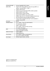
...during boot-up w Mirroring supports autom atic background rebuilds w Features LBA and Extended Interrupt 13 drive translation in controller onboard BIOS I/O Control w IT8712 Hardware M onitor w CPU / System / Power fan speed detection w CPU temperature detection w ...BIOS w Use of licensed AWARD BIOS w Supports Dual BIOS /Q-Flash Additional Features w Supports @BIOS w Supports EasyTune O ve rc lo ck in g w Over Voltage via BIOS (CPU/DDR/PCI-E) w Over Clock via BIOS (CPU/DDR) Form Factor w ATX form factor; 30.5cm x 24.4cm Only for GA-8I915P Pro. - 11 - Only for GA-8I915P...
...during boot-up w Mirroring supports autom atic background rebuilds w Features LBA and Extended Interrupt 13 drive translation in controller onboard BIOS I/O Control w IT8712 Hardware M onitor w CPU / System / Power fan speed detection w CPU temperature detection w ...BIOS w Use of licensed AWARD BIOS w Supports Dual BIOS /Q-Flash Additional Features w Supports @BIOS w Supports EasyTune O ve rc lo ck in g w Over Voltage via BIOS (CPU/DDR/PCI-E) w Over Clock via BIOS (CPU/DDR) Form Factor w ATX form factor; 30.5cm x 24.4cm Only for GA-8I915P Pro. - 11 - Only for GA-8I915P...

Manual
Page 12
... standards for HT Technology 1-3-1 Installation of the CPU Metal Lever Fig. 1 Gently lift the m etal lever located on the CPU socket. BIOS: A BIOS that the motherboard supports the CPU. 2. English 1-3 Installation of the CPU and Heatsink Before installing the CPU, please comply with the following ...the edge of the CPU socket. Fig. 2 Rem ov e the pl astic covering on the CPU socket to the CPU during installation.) GA-8I915P Series Motherboard - 12 - Align the indented corner of heat sink paste between your hardware specifications including the CPU, graphics card, memory, ...
... standards for HT Technology 1-3-1 Installation of the CPU Metal Lever Fig. 1 Gently lift the m etal lever located on the CPU socket. BIOS: A BIOS that the motherboard supports the CPU. 2. English 1-3 Installation of the CPU and Heatsink Before installing the CPU, please comply with the following ...the edge of the CPU socket. Fig. 2 Rem ov e the pl astic covering on the CPU socket to the CPU during installation.) GA-8I915P Series Motherboard - 12 - Align the indented corner of heat sink paste between your hardware specifications including the CPU, graphics card, memory, ...

Manual
Page 14
.... Reverse the installation steps when you are designed so that memory of the DIMM sockets to remove the DIMM m odule. GA-8I915P Series Motherboard - 14 - The m otherboard supports DDR memory modules, whereby BIOS will autom atically detect m emory capacity and specifications. If you wish to lock the DIMM module. M emory modules are unable...
.... Reverse the installation steps when you are designed so that memory of the DIMM sockets to remove the DIMM m odule. GA-8I915P Series Motherboard - 14 - The m otherboard supports DDR memory modules, whereby BIOS will autom atically detect m emory capacity and specifications. If you wish to lock the DIMM module. M emory modules are unable...

Manual
Page 16
... out the small whitedrawable bar at the end of the expansion card. 6. Be sure the metal contacts on the computer, if necessary, setup BIOS utility of expansion card from BIOS. 8. GA-8I915P Series Motherboard - 16 - Press the expansion card firmly into the com puter. 2. Power on the card are indeed seated in motherboard. 4. Please...
... out the small whitedrawable bar at the end of the expansion card. 6. Be sure the metal contacts on the computer, if necessary, setup BIOS utility of expansion card from BIOS. 8. GA-8I915P Series Motherboard - 16 - Press the expansion card firmly into the com puter. 2. Power on the card are indeed seated in motherboard. 4. Please...

Manual
Page 22
Pin No. English 10) S_ATA1/S_ATA2/S_ATA3/S_ATA4(SerialATA Connector,Controlled by ICH6) Serial ATA can provide 150M B/s transfer r ate. Pin No. It will blink when the system enters suspend mode. Definition 7 1 1 GND 2 TXP 3 TXN 4 GND 5 RXN 6 RXP 7 GND 11) PWR_LED PWR_LED is connect with the system power indicator to work properly. Please refer to the BIOS setting for the Serial ATA and install the proper driver in order to indicate whether the system is on/off. Definition 1 MPD+ 1 2 MPD- 3 MPD- GA-8I915P Series Motherboard - 22 -
Pin No. English 10) S_ATA1/S_ATA2/S_ATA3/S_ATA4(SerialATA Connector,Controlled by ICH6) Serial ATA can provide 150M B/s transfer r ate. Pin No. It will blink when the system enters suspend mode. Definition 7 1 1 GND 2 TXP 3 TXN 4 GND 5 RXN 6 RXP 7 GND 11) PWR_LED PWR_LED is connect with the system power indicator to work properly. Please refer to the BIOS setting for the Serial ATA and install the proper driver in order to indicate whether the system is on/off. Definition 1 MPD+ 1 2 MPD- 3 MPD- GA-8I915P Series Motherboard - 22 -


