Manual
Page 8
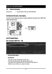
... Help Menu Level` KLJI: Move Enter: Select F5: Previous Values +/-/PU/PD: Value F10: Save F6: Fail-Save Default ESC: Exit F1: General Help F7: Optimized Defaults Reset Case Open Status Case Opened If the case is closed, "Case Opened" will show "No". Only for GA-8I915GM-G 1-2 Feature Summary Onboard LAN Š Onboard Realtek 8110S chip (10/100/1000 Mbit) CI (Chassis Intrusion, Case Open) This 2-pin connector allows...
... Help Menu Level` KLJI: Move Enter: Select F5: Previous Values +/-/PU/PD: Value F10: Save F6: Fail-Save Default ESC: Exit F1: General Help F7: Optimized Defaults Reset Case Open Status Case Opened If the case is closed, "Case Opened" will show "No". Only for GA-8I915GM-G 1-2 Feature Summary Onboard LAN Š Onboard Realtek 8110S chip (10/100/1000 Mbit) CI (Chassis Intrusion, Case Open) This 2-pin connector allows...

Manual
Page 10
...; 8 USB 2.0/1.1 ports (rear x 4, front x 4 via cable) Š 3 IEEE1394 ports (requires cable) Š 1 front audio connector Š 1 IR connector Š 1 PS/2 keyboard port Š 1 PS/2 mouse port Š Onboard Realtek 8110S chip (10/100/1000 Mbit) Š Onboard Realtek 8100C chip (10/100 Mbit) Š 1 RJ 45 port Š ALC880 CODEC Š High Definition Audio Š Supports 2 / 4 / 6 / 8 channel audio Š Supports Line In ; Only for GA-8I915GM. English 1-2 Feature Summary CPU Chipset Memory Slots IDE Connections FDD Connections Onboard SATA Peripherals Onboard LAN Onboard Audio...
...; 8 USB 2.0/1.1 ports (rear x 4, front x 4 via cable) Š 3 IEEE1394 ports (requires cable) Š 1 front audio connector Š 1 IR connector Š 1 PS/2 keyboard port Š 1 PS/2 mouse port Š Onboard Realtek 8110S chip (10/100/1000 Mbit) Š Onboard Realtek 8100C chip (10/100 Mbit) Š 1 RJ 45 port Š ALC880 CODEC Š High Definition Audio Š Supports 2 / 4 / 6 / 8 channel audio Š Supports Line In ; Only for GA-8I915GM. English 1-2 Feature Summary CPU Chipset Memory Slots IDE Connections FDD Connections Onboard SATA Peripherals Onboard LAN Onboard Audio...

Manual
Page 20
... 2 1 GA-8I915G-MF/GA-8I915GM Motherboard - 20 - Please remember to connect the power to the CPU fan to the FDD drive. Please connect the red power connector wire to prevent system overheating and failure. The black connector wire is used to connect the FDD cable while the other end of FDD drives supported are designed with color-coded power connector wires. The types of the cable connects to prevent CPU overheating and failure. 1 CPU_FAN 1 SYS_FAN Pin No. 1 2 3 4 Definition GND +12V Sense Speed Control...
... 2 1 GA-8I915G-MF/GA-8I915GM Motherboard - 20 - Please remember to connect the power to the CPU fan to the FDD drive. Please connect the red power connector wire to prevent system overheating and failure. The black connector wire is used to connect the FDD cable while the other end of FDD drives supported are designed with color-coded power connector wires. The types of the cable connects to prevent CPU overheating and failure. 1 CPU_FAN 1 SYS_FAN Pin No. 1 2 3 4 Definition GND +12V Sense Speed Control...
Manual
Page 21
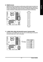
... 7 GND - 21 - Hardware Installation English 6) IDE (IDE Connector) An IDE device connects to work properly. Pin No. Please refer to the BIOS setting for information on settings, please refer to two IDE devices (hard drive or optical drive). One IDE connector can then connect to the instructions located on one IDE cable, and the single IDE cable can connect to one IDE device as Master and the other as Slave (for the Serial ATA and install the proper driver in order to...
... 7 GND - 21 - Hardware Installation English 6) IDE (IDE Connector) An IDE device connects to work properly. Pin No. Please refer to the BIOS setting for information on settings, please refer to two IDE devices (hard drive or optical drive). One IDE connector can then connect to the instructions located on one IDE cable, and the single IDE cable can connect to one IDE device as Master and the other as Slave (for the Serial ATA and install the proper driver in order to...

Manual
Page 22
...+ HD (IDE Hard Disk Active LED) SPEAK (Speaker Connector) RES (Reset Switch) PW (Power Switch) MSG(Message LED/Power/Sleep LED) NC IDE Hard Disk Active LED Reset Switch Pin 1: LED anode(+) Pin 2: LED cathode(-) Pin 1: VCC(+) Pin 2- Pin 3: NC Pin 4: Data(-) Open: Normal Operation Close: Reset Hardware System Open: Normal Operation Close: Power On/Off Pin 1: LED anode(+) Pin 2: LED cathode(-) NC GA-8I915G-MF/GA-8I915GM Motherboard - 22 - English 8) F_PANEL (Front Panel Jumper) Please connect the power LED, PC peaker, reset switch and power switch etc of your chassis front panel to the...
...+ HD (IDE Hard Disk Active LED) SPEAK (Speaker Connector) RES (Reset Switch) PW (Power Switch) MSG(Message LED/Power/Sleep LED) NC IDE Hard Disk Active LED Reset Switch Pin 1: LED anode(+) Pin 2: LED cathode(-) Pin 1: VCC(+) Pin 2- Pin 3: NC Pin 4: Data(-) Open: Normal Operation Close: Reset Hardware System Open: Normal Operation Close: Power On/Off Pin 1: LED anode(+) Pin 2: LED cathode(-) NC GA-8I915G-MF/GA-8I915GM Motherboard - 22 - English 8) F_PANEL (Front Panel Jumper) Please connect the power LED, PC peaker, reset switch and power switch etc of your chassis front panel to the...

Manual
Page 30
... Temperature, voltage, fan, speed. „ MB Intelligent Tweaker(M.I .T.) ESC: Quit F8: Q-Flash Load Fail-Safe Defaults Load Optimized Defaults Set Supervisor Password Set User Password Save & Exit Setup Exit Without Saving KLJI: Select Item F10: Save & Exit Setup Time, Date, Hard Disk Type... GA-8I915G-MF/GA-8I915GM Motherboard - 30 - Please Load Optimized Defaults in best performance configuration. „ Set Supervisor Password Change, set, or disable password. It allows you to limit access to the system and Setup, or just to accept or enter the sub-menu...
... Temperature, voltage, fan, speed. „ MB Intelligent Tweaker(M.I .T.) ESC: Quit F8: Q-Flash Load Fail-Safe Defaults Load Optimized Defaults Set Supervisor Password Set User Password Save & Exit Setup Exit Without Saving KLJI: Select Item F10: Save & Exit Setup Time, Date, Hard Disk Type... GA-8I915G-MF/GA-8I915GM Motherboard - 30 - Please Load Optimized Defaults in best performance configuration. „ Set Supervisor Password Change, set, or disable password. It allows you to limit access to the system and Setup, or just to accept or enter the sub-menu...
Manual
Page 32
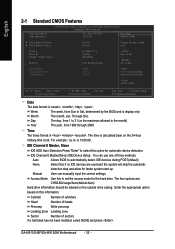
... Help Menu Level` ` IDE Channel 0 Master ` IDE Channel 0 Slave [None] [None] Change the day, month, year Drive A Drive B Floppy 3 Mode Suport Holt On [1.44M, 3.5"] [None] [Disabled] [All, But Keyboard] Sun. The time is 13:00:00. Manual User can use one of sectors If a hard disk has not been installed, select NONE and press . to Dec. to Sat. IDE Channel 0 Master, Slave IDE HDD Auto-Detection Press "Enter" to Sat, determined by the BIOS and...
... Help Menu Level` ` IDE Channel 0 Master ` IDE Channel 0 Slave [None] [None] Change the day, month, year Drive A Drive B Floppy 3 Mode Suport Holt On [1.44M, 3.5"] [None] [Disabled] [All, But Keyboard] Sun. The time is 13:00:00. Manual User can use one of sectors If a hard disk has not been installed, select NONE and press . to Dec. to Sat. IDE Channel 0 Master, Slave IDE HDD Auto-Detection Press "Enter" to Sat, determined by the BIOS and...

Manual
Page 34
... when you install the Intel® Pentium® 4 processor with HT Technology. GA-8I915G-MF/GA-8I915GM Motherboard - 34 - USB-FDD Select your boot device priority by ZIP. First / Second / Third Boot Device Floppy Select your boot device priority by LS120. to 3 On-Chip Frame Buffer Size No-Execute Memory Protect (Note) CPU Enhanced Halt (C1E) (Note) CPU Thermal Monitor 2(TM2) (Note) [Press Enter] [Floppy] [Hard Disk] [CDROM] [Setup] [Enabled] [Enabled] [8MB] [Disabled] [Disabled] [Disabled] Item Help Menu Level` Select Hard Disk Boot Device Priority KLJI...
... when you install the Intel® Pentium® 4 processor with HT Technology. GA-8I915G-MF/GA-8I915GM Motherboard - 34 - USB-FDD Select your boot device priority by ZIP. First / Second / Third Boot Device Floppy Select your boot device priority by LS120. to 3 On-Chip Frame Buffer Size No-Execute Memory Protect (Note) CPU Enhanced Halt (C1E) (Note) CPU Thermal Monitor 2(TM2) (Note) [Press Enter] [Floppy] [Hard Disk] [CDROM] [Setup] [Enabled] [Enabled] [8MB] [Disabled] [Disabled] [Disabled] Item Help Menu Level` Select Hard Disk Boot Device Priority KLJI...

Manual
Page 36
... CMOS Setup Utility-Copyright (C) 1984-2004 Award Software Integrated Peripherals On-Chip Primary PCI IDE On-Chip SATA Mode x PATA IDE Set to SATA Port 0/2 Set to SATA Port 1/3 Set to use. Set On-Chip SATA mode to Non-Combined, SATA will auto detect. (Default value) Set On-Chip SATA mode to Combined, you can use up to 6 HDDs to USB Controller USB 2.0 Controller USB Keyboard Support USB Mouse Support Azalia Codec Front Panel Type Onboard H/W 1394 1 Onboard H/W LAN Onboard LAN Boot ROM Onboard Serial Port 1 Onboard Serial Port 2 UART Mode Select x UR2 Duplex Mode [Enabled] [Auto...
... CMOS Setup Utility-Copyright (C) 1984-2004 Award Software Integrated Peripherals On-Chip Primary PCI IDE On-Chip SATA Mode x PATA IDE Set to SATA Port 0/2 Set to SATA Port 1/3 Set to use. Set On-Chip SATA mode to Non-Combined, SATA will auto detect. (Default value) Set On-Chip SATA mode to Combined, you can use up to 6 HDDs to USB Controller USB 2.0 Controller USB Keyboard Support USB Mouse Support Azalia Codec Front Panel Type Onboard H/W 1394 1 Onboard H/W LAN Onboard LAN Boot ROM Onboard Serial Port 1 Onboard Serial Port 2 UART Mode Select x UR2 Duplex Mode [Enabled] [Auto...

Manual
Page 37
... Enable USB 2.0 Controller. (Default value) Disabled Disable USB 2.0 Controller. Onboard LAN Boot ROM This function decide whether to AC97. SATA Port 0/2 Set to This value will auto set to ". BIOS Setup If PATA IDE were set to Ch. 1 Master/Slave, this function will auto make by the setting "On-Chip SATA Mode" and "PATA IDE Set to Ch. 0 Master/Slave. AC97 HD Audio Set front audio panel type to invoke the boot ROM of the onboard LAN chip. Enabled Enable this function. USB Keyboard Support Enabled Enable USB Keyboard Support. English PATA IDE Set...
... Enable USB 2.0 Controller. (Default value) Disabled Disable USB 2.0 Controller. Onboard LAN Boot ROM This function decide whether to AC97. SATA Port 0/2 Set to This value will auto set to ". BIOS Setup If PATA IDE were set to Ch. 1 Master/Slave, this function will auto make by the setting "On-Chip SATA Mode" and "PATA IDE Set to Ch. 0 Master/Slave. AC97 HD Audio Set front audio panel type to invoke the boot ROM of the onboard LAN chip. Enabled Enable this function. USB Keyboard Support Enabled Enable USB Keyboard Support. English PATA IDE Set...

Manual
Page 43
... a 4-pin fan power cable. In fact, the Voltage option can 't boot, clear CMOS to PWM when you use only. However, some 4-pin CPU fan power cables are not designed following Intel 4-wire fans PWM control specifications. BIOS Setup The option will display "Locked" and read only if the CPU ratio is enabled. PWM Set to overcome wrong frequency issue. Memory Frequency For Wrong frequency may cause your system broken. Auto BIOS autodetects the type of CPU fan you installed and sets the optimal CPU Smart FAN control mode for FSB(Front Side Bus) frequency...
... a 4-pin fan power cable. In fact, the Voltage option can 't boot, clear CMOS to PWM when you use only. However, some 4-pin CPU fan power cables are not designed following Intel 4-wire fans PWM control specifications. BIOS Setup The option will display "Locked" and read only if the CPU ratio is enabled. PWM Set to overcome wrong frequency issue. Memory Frequency For Wrong frequency may cause your system broken. Auto BIOS autodetects the type of CPU fan you installed and sets the optimal CPU Smart FAN control mode for FSB(Front Side Bus) frequency...
Manual
Page 45
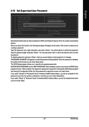
The BIOS Setup program allows you are prompted to enter password. If you select "Setup" at "Password Check" in Advance BIOS Features Menu, you will be asked to confirm the password. English 2-10 Set Supervisor/User Password CMOS Setup Utility-Copyright (C) 1984-2004 Award Software ` Standard CMOS Features ` Advanced BIOS Features ` Integrated Peripherals ` Power Management Setup ` PnP/PCI ConfigurationEsnter Password: ` PC Health Status ` MB Intelligent Tweaker(M.I.T.) Load Fail-Safe Defaults Load Optimized Defaults Set Supervisor Password Set User Password Save & Exit Setup Exit ...
The BIOS Setup program allows you are prompted to enter password. If you select "Setup" at "Password Check" in Advance BIOS Features Menu, you will be asked to confirm the password. English 2-10 Set Supervisor/User Password CMOS Setup Utility-Copyright (C) 1984-2004 Award Software ` Standard CMOS Features ` Advanced BIOS Features ` Integrated Peripherals ` Power Management Setup ` PnP/PCI ConfigurationEsnter Password: ` PC Health Status ` MB Intelligent Tweaker(M.I.T.) Load Fail-Safe Defaults Load Optimized Defaults Set Supervisor Password Set User Password Save & Exit Setup Exit ...

Manual
Page 47
... item that came with your motherboard into your CD-ROM drive, the driver CD-title will scan automatically the system and then list all items defaulted. Insert the driver CD-title that you can install others application. System will auto-detect the right USB2.0 driver). - 47 - English Chapter 3 Install Drivers Pictures below are shown in "Universal Serial Bus controller" under Windows XP operating system, please use Windows Service Pack.
... item that came with your motherboard into your CD-ROM drive, the driver CD-title will scan automatically the system and then list all items defaulted. Insert the driver CD-title that you can install others application. System will auto-detect the right USB2.0 driver). - 47 - English Chapter 3 Install Drivers Pictures below are shown in "Universal Serial Bus controller" under Windows XP operating system, please use Windows Service Pack.
Manual
Page 51
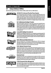
... relative speed and ease. feature, users no longer required to switch into a single mode now gives any user the ability to control and enhance their computer system to -date drivers and BIOS. - 51 - C.O.M. (Corporate Online Management) A web-based system management tool that eliminates system boot-up the PC chassis and short-circuit the "Clear CMOS" pins or the battery on the U-Plus D.P.S. C.I.A.2 (CPU Intelligent Accelerator 2) GIGABYTE CPU Intelligent...
... relative speed and ease. feature, users no longer required to switch into a single mode now gives any user the ability to control and enhance their computer system to -date drivers and BIOS. - 51 - C.O.M. (Corporate Online Management) A web-based system management tool that eliminates system boot-up the PC chassis and short-circuit the "Clear CMOS" pins or the battery on the U-Plus D.P.S. C.I.A.2 (CPU Intelligent Accelerator 2) GIGABYTE CPU Intelligent...

Manual
Page 57
... Floppy Save Backup BIOS to perform these actions. - 57 - CMOS Setup Utility-Copyright (C) 1984-2004 Award Software Standard CMOS Features Advanced BIOS Features Integrated Peripherals Power Management Setup PnP/PCI Configurations PC Health Status MB Intelligent Tweaker(M.I.T.) ESC: Quit F8: Dual BIOS/Q-Flash Select Language Load Fail-Safe Defaults Load Optimized Defaults Set Supervisor Password Set User Password Save & Exit Setup Exit Without Saving F3: Change Language F10: Save & Exit Setup Time, Date, Hard Disk Type... Blocking a task and pressing Enter key on your keyboard...
... Floppy Save Backup BIOS to perform these actions. - 57 - CMOS Setup Utility-Copyright (C) 1984-2004 Award Software Standard CMOS Features Advanced BIOS Features Integrated Peripherals Power Management Setup PnP/PCI Configurations PC Health Status MB Intelligent Tweaker(M.I.T.) ESC: Quit F8: Dual BIOS/Q-Flash Select Language Load Fail-Safe Defaults Load Optimized Defaults Set Supervisor Password Set User Password Save & Exit Setup Exit Without Saving F3: Change Language F10: Save & Exit Setup Time, Date, Hard Disk Type... Blocking a task and pressing Enter key on your keyboard...

Manual
Page 58
... previously downloaded to flash and press Enter. After pressing Enter, you'll then see the progress of reading the BIOS file from Floppy" item in the Q-Flash menu and press Enter button. GA-8I915G-MF/GA-8I915GM Motherboard - 58 - As described in the "Before you begin" section above, you must prepare a floppy disk having the BIOS file for backup purpose, you can begin Step 1 with "Save Main BIOS to flash BIOS. Steps: 1. Dual BIOS Utility Boot From Main Bios Main ROM Type/Size...
... previously downloaded to flash and press Enter. After pressing Enter, you'll then see the progress of reading the BIOS file from Floppy" item in the Q-Flash menu and press Enter button. GA-8I915G-MF/GA-8I915GM Motherboard - 58 - As described in the "Before you begin" section above, you must prepare a floppy disk having the BIOS file for backup purpose, you can begin Step 1 with "Save Main BIOS to flash BIOS. Steps: 1. Dual BIOS Utility Boot From Main Bios Main ROM Type/Size...

Manual
Page 59
... Disable Boot From Main Bios !A! Load Default Settings Save Settings to CMOS Q-Flash Utility Load Main BIOS from Floppy Load Backup BIOS from Floppy Save Main BIOS to Floppy Save Backup BIOS to Floppy Enter : Run :Move ESC:Reset F10:Power Off You can repeat Step 1 to 4 to flash the backup BIOS, too. 5. Award Modular BIOS v6.00PG, An Energy Star Ally Copyright (C) 1984-2003, Award Software, Inc. Appendix Press any keys to return to update BIOS. Press Esc and then Y button to enter SETUP / Dual BIOS / Q-Flash / F9 For Xpress Recovery...
... Disable Boot From Main Bios !A! Load Default Settings Save Settings to CMOS Q-Flash Utility Load Main BIOS from Floppy Load Backup BIOS from Floppy Save Main BIOS to Floppy Save Backup BIOS to Floppy Enter : Run :Move ESC:Reset F10:Power Off You can repeat Step 1 to 4 to flash the backup BIOS, too. 5. Award Modular BIOS v6.00PG, An Energy Star Ally Copyright (C) 1984-2003, Award Software, Inc. Appendix Press any keys to return to update BIOS. Press Esc and then Y button to enter SETUP / Dual BIOS / Q-Flash / F9 For Xpress Recovery...
Manual
Page 60
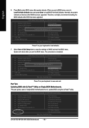
... in BIOS menu, move to Load Fail-Safe Defaults item and press Enter to load BIOS Fail-Safe Defaults. When you exit the BIOS menu. Normally the system redetects all devices after BIOS has been upgraded. GA-8I915G-MF/GA-8I915GM Motherboard - 60 - Therefore, we highly recommend reloading the BIOS defaults after BIOS has been upgraded. The procedure is completed. This part guides users of single-BIOS motherboards how to save the settings to CMOS and EXIT (SYe/tNS)u?pYervisor Password PnP/PCI Configurations Set User Password...
... in BIOS menu, move to Load Fail-Safe Defaults item and press Enter to load BIOS Fail-Safe Defaults. When you exit the BIOS menu. Normally the system redetects all devices after BIOS has been upgraded. GA-8I915G-MF/GA-8I915GM Motherboard - 60 - Therefore, we highly recommend reloading the BIOS defaults after BIOS has been upgraded. The procedure is completed. This part guides users of single-BIOS motherboards how to save the settings to CMOS and EXIT (SYe/tNS)u?pYervisor Password PnP/PCI Configurations Set User Password...
Manual
Page 63
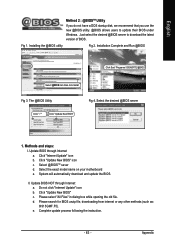
... click "Internet Update" icon b. Please select "All Files" in dialog box while opening the old file. The @BIOS Utility Click " " Click "Update New BIOS" Fig 4. Select the desired @BIOS server 1. Update BIOS NOT through Internet a. d. Just select the desired @BIOS server to update their BIOS under Windows. Select the exact model name on your motherboard e. System will automatically download and update the BIOS. Fig 1. Complete update process following the instruction. - 63...
... click "Internet Update" icon b. Please select "All Files" in dialog box while opening the old file. The @BIOS Utility Click " " Click "Update New BIOS" Fig 4. Select the desired @BIOS server 1. Update BIOS NOT through Internet a. d. Just select the desired @BIOS server to update their BIOS under Windows. Select the exact model name on your motherboard e. System will automatically download and update the BIOS. Fig 1. Complete update process following the instruction. - 63...
Manual
Page 69
... 1 long 2 short: Monitor or display card error 1 long 3 short: Keyboard error 9 beeps ROM checksum error 1 long 9 short: BIOS ROM error 10 beeps CMOS shutdown register read/write error Continuous long beeps: DRAM error 11 beeps Cache memory bad Continuous short beeps: Power error - 69 - If not, please change another speaker with an internal amplifier. The situations might differ from case to the maximum volume? Disconnect the power cord from computer after updating BIOS. What do I clear CMOS? Answer: Please make sure the speaker you can use a metal object to connect the...
... 1 long 2 short: Monitor or display card error 1 long 3 short: Keyboard error 9 beeps ROM checksum error 1 long 9 short: BIOS ROM error 10 beeps CMOS shutdown register read/write error Continuous long beeps: DRAM error 11 beeps Cache memory bad Continuous short beeps: Power error - 69 - If not, please change another speaker with an internal amplifier. The situations might differ from case to the maximum volume? Disconnect the power cord from computer after updating BIOS. What do I clear CMOS? Answer: Please make sure the speaker you can use a metal object to connect the...


