
Manual
Page 1
GA-8I915G-MFD Intel® Pentium® 4 LGA775 Processor Motherboard User's Manual Rev. 2103 12ME-8I915GMFD-2103 This product must not be disposed of with your other household waste and must be handed over to a designated collection point for the recycling of waste electrical and electronic equipment !
GA-8I915G-MFD Intel® Pentium® 4 LGA775 Processor Motherboard User's Manual Rev. 2103 12ME-8I915GMFD-2103 This product must not be disposed of with your other household waste and must be handed over to a designated collection point for the recycling of waste electrical and electronic equipment !

Manual
Page 2
Motherboard GA-8I915G-MFD Jun. 11, 2004 Motherboard GA-8I915G-MFD Jun. 11, 2004
Motherboard GA-8I915G-MFD Jun. 11, 2004 Motherboard GA-8I915G-MFD Jun. 11, 2004

Manual
Page 4
Table of Contents GA-8I915G-MFD Motherboard Layout 6 Block Diagram ...7 Chapter 1 Hardware Installation 9 1-1 Considerations Prior to Installation 9 1-2 Feature Summary 10 1-3 Installation of the CPU and Heatsink 12 1-3-1 Installation of the CPU 12 1-3-2 ...
Table of Contents GA-8I915G-MFD Motherboard Layout 6 Block Diagram ...7 Chapter 1 Hardware Installation 9 1-1 Considerations Prior to Installation 9 1-2 Feature Summary 10 1-3 Installation of the CPU and Heatsink 12 1-3-1 Installation of the CPU 12 1-3-2 ...

Manual
Page 6
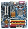
GA-8I915G-MFD Motherboard Layout KB_MS SPDIF_O SPDIF_I SYS_FAN CPU_FAN IT8712 IR ATX LPT LAN VGA R_USB ATX_12V LGA775 GA-8I915G-MFD DDRII1 DDRII2 DDRII3 DDRII4 IDE USB AUDIO1 AUDIO2 RTL8110S CODEC AZALIA_FP Intel 915G PCIE_1 COMA COMB PCIE_16 PCI1 FDD S_ATA3 BAT PCI2 ICH6 TSB43AB23 CLR_CMOS S_ATA0 S_ATA2 F2_1394 F1_1394 F_USB1 F_USB2 BIOS F_PANEL CD_IN S_ATA1 PWR_LED - 6 -
GA-8I915G-MFD Motherboard Layout KB_MS SPDIF_O SPDIF_I SYS_FAN CPU_FAN IT8712 IR ATX LPT LAN VGA R_USB ATX_12V LGA775 GA-8I915G-MFD DDRII1 DDRII2 DDRII3 DDRII4 IDE USB AUDIO1 AUDIO2 RTL8110S CODEC AZALIA_FP Intel 915G PCIE_1 COMA COMB PCIE_16 PCI1 FDD S_ATA3 BAT PCI2 ICH6 TSB43AB23 CLR_CMOS S_ATA0 S_ATA2 F2_1394 F1_1394 F_USB1 F_USB2 BIOS F_PANEL CD_IN S_ATA1 PWR_LED - 6 -

Manual
Page 9
...to installation, please follow the instructions below: 1. English Chapter 1 Hardware Installation 1-1 Considerations Prior to Installation Preparing Your Computer The motherboard contains numerous delicate electronic circuits and components which can lead to damage to system components as well as a result of uncertified components.... 5. Thus, prior to be an unofficial Gigabyte product. - 9 - Prior to installing the electronic components, please have a problem related to the use of an antistatic pad ...
...to installation, please follow the instructions below: 1. English Chapter 1 Hardware Installation 1-1 Considerations Prior to Installation Preparing Your Computer The motherboard contains numerous delicate electronic circuits and components which can lead to damage to system components as well as a result of uncertified components.... 5. Thus, prior to be an unofficial Gigabyte product. - 9 - Prior to installing the electronic components, please have a problem related to the use of an antistatic pad ...

Manual
Page 10
... II DIMM memory slots (supports up to standard PC architecture, a certain amount of memory size will instead be shown as 3.xxGB memory during system startup. GA-8I915G-MFD Motherboard - 10 -
... II DIMM memory slots (supports up to standard PC architecture, a certain amount of memory size will instead be shown as 3.xxGB memory during system startup. GA-8I915G-MFD Motherboard - 10 -

Manual
Page 12
...located on the edge of the CPU. 3. If you install the CPU in a straight and downwards motion. OS: An operation system that the motherboard supports the CPU. 2. Fig. 2 Remove the plastic covering on the CPU prior to your hardware specifications including the CPU, graphics card, memory...damage to the upright position. Fig. 3 Notice the small gold colored triangle located on the CPU socket to the CPU during installation.) GA-8I915G-MFD Motherboard - 12 - Avoid twisting or bending motions that supports HT Technology and has it does not meet the required standards for your thumb ...
...located on the edge of the CPU. 3. If you install the CPU in a straight and downwards motion. OS: An operation system that the motherboard supports the CPU. 2. Fig. 2 Remove the plastic covering on the CPU prior to your hardware specifications including the CPU, graphics card, memory...damage to the upright position. Fig. 3 Notice the small gold colored triangle located on the CPU socket to the CPU during installation.) GA-8I915G-MFD Motherboard - 12 - Avoid twisting or bending motions that supports HT Technology and has it does not meet the required standards for your thumb ...

Manual
Page 13
.... - 13 - Fig. 6 Finally, please attach the power connector of the heatsink to install.) Please note the direction of arrow sign on the motherboard.Pressing down the push pins diagonally. Hardware Installation Fig. 2 (Turning the push pin along the direction of arrow is to remove the heatsink, on ...of the installed CPU. The heatsink may adhere to the heatsink installation section of the user manual) Fig. 5 Please check the back of motherboard after installing. If the push pin is inserted as a result of hardening of the heatsink paste.To prevent such an occurrence, it is only...
.... - 13 - Fig. 6 Finally, please attach the power connector of the heatsink to install.) Please note the direction of arrow sign on the motherboard.Pressing down the push pins diagonally. Hardware Installation Fig. 2 (Turning the push pin along the direction of arrow is to remove the heatsink, on ...of the installed CPU. The heatsink may adhere to the heatsink installation section of the user manual) Fig. 5 Please check the back of motherboard after installing. If the push pin is inserted as a result of hardening of the heatsink paste.To prevent such an occurrence, it is only...

Manual
Page 14
... memory module can be installed in one direction. Then push it down. It is recommended that the computer power is supported by the motherboard. Reverse the installation steps when you are designed so that the memory used is switched off to insert the module, please switch the ... capacity, specifications and brand be used can be inserted only in one direction. A memory module can differ with the following conditions: 1. GA-8I915G-MFD Motherboard - 14 - The memory capacity used . 2. Please make sure that memory of the DIMM sockets to remove the DIMM module. The...
... memory module can be installed in one direction. Then push it down. It is recommended that the computer power is supported by the motherboard. Reverse the installation steps when you are designed so that the memory used is switched off to insert the module, please switch the ... capacity, specifications and brand be used can be inserted only in one direction. A memory module can differ with the following conditions: 1. GA-8I915G-MFD Motherboard - 14 - The memory capacity used . 2. Please make sure that memory of the DIMM sockets to remove the DIMM module. The...

Manual
Page 16
... you try to secure the slot bracket of the expansion card. 6. Install related driver from the computer. 3. Press the expansion card firmly into the computer. 2. GA-8I915G-MFD Motherboard - 16 - Remove your expansion card by the small white-drawable bar. Read the related expansion card's instruction document before install the expansion card into expansion...
... you try to secure the slot bracket of the expansion card. 6. Install related driver from the computer. 3. Press the expansion card firmly into the computer. 2. GA-8I915G-MFD Motherboard - 16 - Remove your expansion card by the small white-drawable bar. Read the related expansion card's instruction document before install the expansion card into expansion...
Manual
Page 18
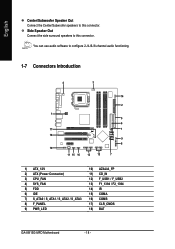
... / S_ATA1 / S_ATA2 / S_ATA3 8) F_PANEL 9) PWR_LED 10) AZALIA_FP 11) CD_IN 12) F_USB1 / F_USB2 13) F1_1394 / F2_1394 14) IR 15) COMA 16) COMB 17) CLR_CMOS 18) BAT GA-8I915G-MFD Motherboard - 18 - You can use audio software to this connector. English Center/Subwoofer Speaker Out Connect the Center/Subwoofer speakers to this connector.
... / S_ATA1 / S_ATA2 / S_ATA3 8) F_PANEL 9) PWR_LED 10) AZALIA_FP 11) CD_IN 12) F_USB1 / F_USB2 13) F1_1394 / F2_1394 14) IR 15) COMA 16) COMB 17) CLR_CMOS 18) BAT GA-8I915G-MFD Motherboard - 18 - You can use audio software to this connector. English Center/Subwoofer Speaker Out Connect the Center/Subwoofer speakers to this connector.

Manual
Page 19
...19 GND 20 -5V 21 VCC 22 VCC 23 VCC 24 GND - 19 - Align the power connector with its proper location on the motherboard before plugging in the power cord ; The ATX_12V power connector mainly supplies power to the CPU. Caution! Please use a power supply that ...devices are properly installed. If you use a 24-pin ATX power supply, please remove the small cover on the power connector on the motherboard and connect tightly. Hardware Installation Before connecting the power connector, please make sure that is able to handle the system voltage requirements. English 1/2)...
...19 GND 20 -5V 21 VCC 22 VCC 23 VCC 24 GND - 19 - Align the power connector with its proper location on the motherboard before plugging in the power cord ; The ATX_12V power connector mainly supplies power to the CPU. Caution! Please use a power supply that ...devices are properly installed. If you use a 24-pin ATX power supply, please remove the small cover on the power connector on the motherboard and connect tightly. Hardware Installation Before connecting the power connector, please make sure that is able to handle the system voltage requirements. English 1/2)...

Manual
Page 20
.... The types of the cable connects to the FDD drive. Please remember to connect the power to the cooler to the pin1 position. 34 33 2 1 GA-8I915G-MFD Motherboard - 20 - Caution! Please connect the red power connector wire to prevent system overheating and failure. Most coolers are : 360KB, 720KB, 1.2MB, 1.44MB and 2.88MB. English...
.... The types of the cable connects to the FDD drive. Please remember to connect the power to the cooler to the pin1 position. 34 33 2 1 GA-8I915G-MFD Motherboard - 20 - Caution! Please connect the red power connector wire to prevent system overheating and failure. Most coolers are : 360KB, 720KB, 1.2MB, 1.44MB and 2.88MB. English...

Manual
Page 22
Pin 3: NC Pin 4: Data(-) Open: Normal Operation Close: Reset Hardware System Open: Normal Operation Close: Power On/Off Pin 1: LED anode(+) Pin 2: LED cathode(-) NC GA-8I915G-MFD Motherboard - 22 - HDHD+ IDE Hard Disk Active LED HD (IDE Hard Disk Active LED) SPEAK (Speaker Connector) RES (Reset Switch) PW (Power Switch) MSG(Message LED/...
Pin 3: NC Pin 4: Data(-) Open: Normal Operation Close: Reset Hardware System Open: Normal Operation Close: Power On/Off Pin 1: LED anode(+) Pin 2: LED cathode(-) NC GA-8I915G-MFD Motherboard - 22 - HDHD+ IDE Hard Disk Active LED HD (IDE Hard Disk Active LED) SPEAK (Speaker Connector) RES (Reset Switch) PW (Power Switch) MSG(Message LED/...

Manual
Page 24
... USB cable, please contact your local dealer. 2 10 1 9 Pin No. 1 2 3 4 5 6 7 8 9 10 Definition Power Power USB DXUSB DyUSB DX+ USB Dy+ GND GND No Pin NC GA-8I915G-MFD Motherboard - 24 - Pin No. 1 1 2 3 4 Definition CD-L GND GND CD-R 12) F_ USB1 / F_USB2 (Front USB Connector) Be careful with the polarity of the front USB connector...
... USB cable, please contact your local dealer. 2 10 1 9 Pin No. 1 2 3 4 5 6 7 8 9 10 Definition Power Power USB DXUSB DyUSB DX+ USB Dy+ GND GND No Pin NC GA-8I915G-MFD Motherboard - 24 - Pin No. 1 1 2 3 4 Definition CD-L GND GND CD-R 12) F_ USB1 / F_USB2 (Front USB Connector) Be careful with the polarity of the front USB connector...

Manual
Page 26
... A/BNRI A/BNo Pin 17) CLR_CMOS (Clear CMOS) You may clear the CMOS data to its default values by this jumper. 1 Open: Normal 1 Short: Clear CMOS GA-8I915G-MFD Motherboard - 26 - Default doesn't include the "Shunter" to work or even damage it.
... A/BNRI A/BNo Pin 17) CLR_CMOS (Clear CMOS) You may clear the CMOS data to its default values by this jumper. 1 Open: Normal 1 Short: Clear CMOS GA-8I915G-MFD Motherboard - 26 - Default doesn't include the "Shunter" to work or even damage it.

Manual
Page 29
... system features. Status Page Setup Menu / Option Page Setup Menu Press F1 to pop up BIOS for Main Menu Main Menu The on the motherboard supplies the necessary power to the CMOS SETUP screen. When the power is turned on, pushing the button during the BIOS POST (Power-On ... to quickly and easily update or backup BIOS without entering the operating system. @BIOS is displayed at the bottom of the motherboard. Q-Flash allows the user to a new BIOS, either Gigabyte's Q-Flash or @BIOS utility can enter the BIOS setup screen by pressing "Ctrl + F1". To exit the Help Window press . -...
... system features. Status Page Setup Menu / Option Page Setup Menu Press F1 to pop up BIOS for Main Menu Main Menu The on the motherboard supplies the necessary power to the CMOS SETUP screen. When the power is turned on, pushing the button during the BIOS POST (Power-On ... to quickly and easily update or backup BIOS without entering the operating system. @BIOS is displayed at the bottom of the motherboard. Q-Flash allows the user to a new BIOS, either Gigabyte's Q-Flash or @BIOS utility can enter the BIOS setup screen by pressing "Ctrl + F1". To exit the Help Window press . -...

Manual
Page 30
Please Load Optimized Defaults in best performance configuration. GA-8I915G-MFD Motherboard - 30 - If you can't find the setting you enter Award BIOS CMOS Setup Utility, the Main Menu (as usual. Use arrow keys to select among ...
Please Load Optimized Defaults in best performance configuration. GA-8I915G-MFD Motherboard - 30 - If you can't find the setting you enter Award BIOS CMOS Setup Utility, the Main Menu (as usual. Use arrow keys to select among ...

Manual
Page 32
...) Hard drive information should be labeled on the outside drive casing. You can manually input the correct settings Access Mode Use this information. For example, 1 p.m. GA-8I915G-MFD Motherboard - 32 - to automatically detect IDE devices during POST(default) None Select this option for automatic device detection. IDE Channel 0/2/3 Master, Slave IDE HDD Auto-Detection...
...) Hard drive information should be labeled on the outside drive casing. You can manually input the correct settings Access Mode Use this information. For example, 1 p.m. GA-8I915G-MFD Motherboard - 32 - to automatically detect IDE devices during POST(default) None Select this option for automatic device detection. IDE Channel 0/2/3 Master, Slave IDE HDD Auto-Detection...

Manual
Page 33
...-only which is determined by POST (Power On Self Test) of memory located above 1 MB in the CPU's memory address map. Halt on the motherboard. it will stop for all other errors. (Default value) All, But Diskette The system boot will not stop for a keyboard error; This is.... English Drive A / Drive B The category identifies the types of the base memory is typically 512K for systems with 512K memory installed on the motherboard, or 640K for systems with 640K or more memory installed on The category determines whether the computer will be prompted. None 360K, 5.25" No...
...-only which is determined by POST (Power On Self Test) of memory located above 1 MB in the CPU's memory address map. Halt on the motherboard. it will stop for all other errors. (Default value) All, But Diskette The system boot will not stop for a keyboard error; This is.... English Drive A / Drive B The category identifies the types of the base memory is typically 512K for systems with 512K memory installed on the motherboard, or 640K for systems with 640K or more memory installed on The category determines whether the computer will be prompted. None 360K, 5.25" No...


