Manual
Page 1
GA-8I865GVMK-775 Intel® Pentium® 4 LGA775 Processor Motherboard User's Manual Rev. 1002 12ME-I865GVMKT-1002
GA-8I865GVMK-775 Intel® Pentium® 4 LGA775 Processor Motherboard User's Manual Rev. 1002 12ME-I865GVMKT-1002
Manual
Page 2
Motherboard GA-8I865GVMK-775 June 15, 2005 Motherboard GA-8I865GVMK-775 June 15, 2005
Motherboard GA-8I865GVMK-775 June 15, 2005 Motherboard GA-8I865GVMK-775 June 15, 2005
Manual
Page 4
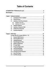
Table of Contents GA-8I865GVMK-775 Motherboard Layout 6 Block Diagram ...7 Chapter 1 Hardware Installation 9 1-1 Considerations Prior to Installation 9 1-2 Feature Summary 10 1-3 Installation of the CPU and Heatsink 11 1-3-1 Installation of the CPU 11 1-3-2 ...
Table of Contents GA-8I865GVMK-775 Motherboard Layout 6 Block Diagram ...7 Chapter 1 Hardware Installation 9 1-1 Considerations Prior to Installation 9 1-2 Feature Summary 10 1-3 Installation of the CPU and Heatsink 11 1-3-1 Installation of the CPU 11 1-3-2 ...
Manual
Page 6
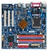
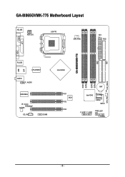
IDE1 GA-8I865GVMK-775 Motherboard Layout KB_MS ATX_12V LGA775 CPU_FAN ATX FDD COMA GA-8I865GVMK-775 DDR1 DDR2 DDR3 DDR4 IDE2 LPT LAN VGA R_USB LPC47M997 USB AUDIO F_AUDIO EP82562G IR CODEC SPDIF CD_IN COMB Intel 865GV PCI1 BIOS PCI2 PCI3 BAT Intel ICH5 SATA0 SATA1 F_USB1 F_USB2 PWR_LED F_PANEL CLR_CMOS SYS_FAN - 6 -
IDE1 GA-8I865GVMK-775 Motherboard Layout KB_MS ATX_12V LGA775 CPU_FAN ATX FDD COMA GA-8I865GVMK-775 DDR1 DDR2 DDR3 DDR4 IDE2 LPT LAN VGA R_USB LPC47M997 USB AUDIO F_AUDIO EP82562G IR CODEC SPDIF CD_IN COMB Intel 865GV PCI1 BIOS PCI2 PCI3 BAT Intel ICH5 SATA0 SATA1 F_USB1 F_USB2 PWR_LED F_PANEL CLR_CMOS SYS_FAN - 6 -

Manual
Page 9
...to natural disaster, accident or human cause. 2. Damage due to be an unofficial Gigabyte product. - 9 - Prior to installation, please do not place the computer system on the motherboard or within a electrostatic shielding container. 5. Damage due to use exceeding the permitted ...Damage as a result of Non-Warranty 1. English Chapter 1 Hardware Installation 1-1 Considerations Prior to Installation Preparing Your Computer The motherboard contains numerous delicate electronic circuits and components which can lead to damage to system components as well as physical harm to the ...
...to natural disaster, accident or human cause. 2. Damage due to be an unofficial Gigabyte product. - 9 - Prior to installation, please do not place the computer system on the motherboard or within a electrostatic shielding container. 5. Damage due to use exceeding the permitted ...Damage as a result of Non-Warranty 1. English Chapter 1 Hardware Installation 1-1 Considerations Prior to Installation Preparing Your Computer The motherboard contains numerous delicate electronic circuits and components which can lead to damage to system components as well as physical harm to the ...
Manual
Page 10
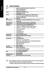
...; 4 DDR DIMM memory slots (supports up to standard PC architecture, a certain amount of memory size will instead be shown as 3.xxGB memory during system startup. GA-8I865GVMK-775 Motherboard - 10 -
...; 4 DDR DIMM memory slots (supports up to standard PC architecture, a certain amount of memory size will instead be shown as 3.xxGB memory during system startup. GA-8I865GVMK-775 Motherboard - 10 -

Manual
Page 11
... CPU. English 1-3 Installation of the CPU and Heatsink Before installing the CPU, please comply with the following platform components: - OS: An operation system that the motherboard supports the CPU. 2. Avoid twisting or bending motions that supports HT Technology and has it into the socket in a straight and downwards motion. Please make...
... CPU. English 1-3 Installation of the CPU and Heatsink Before installing the CPU, please comply with the following platform components: - OS: An operation system that the motherboard supports the CPU. 2. Avoid twisting or bending motions that supports HT Technology and has it into the socket in a straight and downwards motion. Please make...
Manual
Page 12
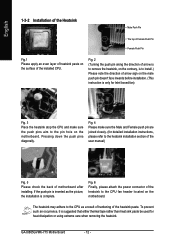
... to the heatsink installation section of the user manual) Fig. 5 Please check the back of motherboard after installing. Fig. 4 Please make sure the push pins aim to the pin hole on the motherboard. If the push pin is inserted as a result of hardening of the heatsink paste. To...heat sink paste be used for detailed installation instructions, please refer to install.) Please note the direction of arrow sign on the contrary, is complete. GA-8I865GVMK-775 Motherboard - 12 - Fig. 2 (Turning the push pin along the direction of arrow is to remove the heatsink, on the male push pin doesn...
... to the heatsink installation section of the user manual) Fig. 5 Please check the back of motherboard after installing. Fig. 4 Please make sure the push pins aim to the pin hole on the motherboard. If the push pin is inserted as a result of hardening of the heatsink paste. To...heat sink paste be used for detailed installation instructions, please refer to install.) Please note the direction of arrow sign on the contrary, is complete. GA-8I865GVMK-775 Motherboard - 12 - Fig. 2 (Turning the push pin along the direction of arrow is to remove the heatsink, on the male push pin doesn...

Manual
Page 13
The motherboard supports DDR memory modules, whereby BIOS will automatically detect memory capacity and specifications. Reverse the installation steps when you are designed so that the memory ... damage. 3. Hardware Installation Please make sure that memory of Memory Before installing the memory modules, please comply with each slot. It is supported by the motherboard.
The motherboard supports DDR memory modules, whereby BIOS will automatically detect memory capacity and specifications. Reverse the installation steps when you are designed so that the memory ... damage. 3. Hardware Installation Please make sure that memory of Memory Before installing the memory modules, please comply with each slot. It is supported by the motherboard.
Manual
Page 14
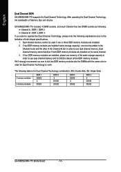
... in the Channel B slot in order to the limitation of Memory Bus will double. If four DDR memory modules are installed on the same channel. 3. GA-8I865GVMK-775 includes 4 DIMM sockets, and each Channel has two DIMM sockets as following: Channel A : DDR 1, DDR 2 Channel B : DDR 3, DDR 4 If you want to operate the Dual... Side) 2 memory modules 4 memory modules DDR 1 DS/SS X DS/SS DDR 2 X DS/SS DS/SS DDR 3 DS/SS X DS/SS DDR 4 X DS/SS DS/SS GA-8I865GVMK-775 Motherboard - 14 - English Dual Channel DDR GA-8I865GVMK-775 supports the Dual Channel Technology.
... in the Channel B slot in order to the limitation of Memory Bus will double. If four DDR memory modules are installed on the same channel. 3. GA-8I865GVMK-775 includes 4 DIMM sockets, and each Channel has two DIMM sockets as following: Channel A : DDR 1, DDR 2 Channel B : DDR 3, DDR 4 If you want to operate the Dual... Side) 2 memory modules 4 memory modules DDR 1 DS/SS X DS/SS DDR 2 X DS/SS DS/SS DDR 3 DS/SS X DS/SS DDR 4 X DS/SS DS/SS GA-8I865GVMK-775 Motherboard - 14 - English Dual Channel DDR GA-8I865GVMK-775 supports the Dual Channel Technology.

Manual
Page 15
... card firmly into the computer. 2. Replace your expansion card by following the steps outlined below: 1. Hardware Installation Power on the card are indeed seated in motherboard. 4. Be sure the metal contacts on the computer, if necessary, setup BIOS utility of the expansion card. 6. Installing a PCI expansion card: - 15 - English 1-5 Installation of...
... card firmly into the computer. 2. Replace your expansion card by following the steps outlined below: 1. Hardware Installation Power on the card are indeed seated in motherboard. 4. Be sure the metal contacts on the computer, if necessary, setup BIOS utility of the expansion card. 6. Installing a PCI expansion card: - 15 - English 1-5 Installation of...
Manual
Page 16
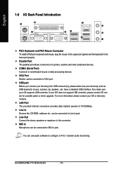
... USB connector(s), please make sure your OS or device(s) vendors. can be connected to Line In jack. You can be connected to MIC In jack. GA-8I865GVMK-775 Motherboard - 16 - English 1-6 I/O Back Panel Introduction PS/2 Keyboard and PS/2 Mouse Connector To install a PS/2 port keyboard and mouse, plug the mouse to the upper port...
... USB connector(s), please make sure your OS or device(s) vendors. can be connected to Line In jack. You can be connected to MIC In jack. GA-8I865GVMK-775 Motherboard - 16 - English 1-6 I/O Back Panel Introduction PS/2 Keyboard and PS/2 Mouse Connector To install a PS/2 port keyboard and mouse, plug the mouse to the upper port...
Manual
Page 18
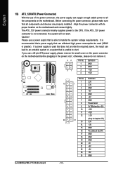
... the power connector, please make sure that is not connected, the system will not start . Please use a power supply that all the components on the motherboard. Definition 1 3.3V 13 1 2 3.3V 3 GND 4 +5V 5 GND 6 +5V 7 GND 8 Power Good 9 5V SB(stand by +5V) 10 +12V 11 +12V 12 3.3V 24... 14 -12V 15 GND 16 PS_ON(soft On/Off) 17 GND 18 GND 19 GND 20 -5V 21 +5V 22 +5V 23 +5V 24 GND GA-8I865GVMK-775 Motherboard - 18 - otherwise, please do not remove it. 42 31 Pin No. 1 2 3 4 Definition GND GND +12V +12V Pin No. Align the power connector with...
... the power connector, please make sure that is not connected, the system will not start . Please use a power supply that all the components on the motherboard. Definition 1 3.3V 13 1 2 3.3V 3 GND 4 +5V 5 GND 6 +5V 7 GND 8 Power Good 9 5V SB(stand by +5V) 10 +12V 11 +12V 12 3.3V 24... 14 -12V 15 GND 16 PS_ON(soft On/Off) 17 GND 18 GND 19 GND 20 -5V 21 +5V 22 +5V 23 +5V 24 GND GA-8I865GVMK-775 Motherboard - 18 - otherwise, please do not remove it. 42 31 Pin No. 1 2 3 4 Definition GND GND +12V +12V Pin No. Align the power connector with...
Manual
Page 20
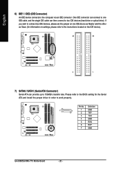
... instructions located on one IDE cable, and the single IDE cable can provide up to work properly. Definition 7 1 1 GND 2 TXP 3 TXN 4 GND 5 RXN 6 RXP 7 GND GA-8I865GVMK-775 Motherboard - 20 - English 6) IDE1 / IDE2 (IDE Connector) An IDE device connects to two IDE devices (hard drive or optical drive). If you wish to connect two...
... instructions located on one IDE cable, and the single IDE cable can provide up to work properly. Definition 7 1 1 GND 2 TXP 3 TXN 4 GND 5 RXN 6 RXP 7 GND GA-8I865GVMK-775 Motherboard - 20 - English 6) IDE1 / IDE2 (IDE Connector) An IDE device connects to two IDE devices (hard drive or optical drive). If you wish to connect two...
Manual
Page 22
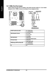
... assignment below. Pin 3: NC Pin 4: Data(-) Open: Normal Close: Reset Hardware System Open: Normal Close: Power On/Off Pin 1: LED anode(+) Pin 2: LED cathode(-) NC GA-8I865GVMK-775 Motherboard - 22 - Message LED/ Power/ Sleep LED Speaker Connector Power Switch MSG+ MSG- RESRES+ NC HD (IDE Hard Disk Active LED) SPEAK (Speaker Connector) RES (Reset...
... assignment below. Pin 3: NC Pin 4: Data(-) Open: Normal Close: Reset Hardware System Open: Normal Close: Power On/Off Pin 1: LED anode(+) Pin 2: LED cathode(-) NC GA-8I865GVMK-775 Motherboard - 22 - Message LED/ Power/ Sleep LED Speaker Connector Power Switch MSG+ MSG- RESRES+ NC HD (IDE Hard Disk Active LED) SPEAK (Speaker Connector) RES (Reset...
Manual
Page 24
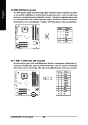
... data to work or even damage it . Definition 1 Power 2 Power 2 1 10 9 3 USB DX- 4 USB Dy- 5 USB DX+ 6 USB Dy+ 7 GND 8 GND 9 No Pin 10 NC GA-8I865GVMK-775 Motherboard - 24 - Use this feature only when your local dealer. English 13) SPDIF (SPDIF Out Connector) The SPDIF output is capable of the front USB connector.
... data to work or even damage it . Definition 1 Power 2 Power 2 1 10 9 3 USB DX- 4 USB Dy- 5 USB DX+ 6 USB Dy+ 7 GND 8 GND 9 No Pin 10 NC GA-8I865GVMK-775 Motherboard - 24 - Use this feature only when your local dealer. English 13) SPDIF (SPDIF Out Connector) The SPDIF output is capable of the front USB connector.
Manual
Page 26
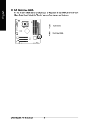
Default doesn't include the "Shunter" to its default values by this jumper. Open: Normal 1 Short: Clear CMOS 1 GA-8I865GVMK-775 Motherboard - 26 - English 17) CLR_CMOS (Clear CMOS) You may clear the CMOS data to prevent from improper use this jumper. To clear CMOS, temporarily short 1-2 pin.
Default doesn't include the "Shunter" to its default values by this jumper. Open: Normal 1 Short: Clear CMOS 1 GA-8I865GVMK-775 Motherboard - 26 - English 17) CLR_CMOS (Clear CMOS) You may clear the CMOS data to prevent from improper use this jumper. To clear CMOS, temporarily short 1-2 pin.

Manual
Page 27
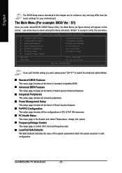
... BIOS, either Gigabyte's Q-Flash or @BIOS utility can enter the BIOS setup screen by pressing "Ctrl + F1". CONTROL KEYS Enter> Move to activate certain system features. Quit and not save the current BIOS to its original settings. You can be reset to a disk in the CMOS SRAM of the motherboard. BIOS Setup... the first time, it is recommended that describes the appropriate keys to use and the possible selections for Main Menu Main Menu The on the motherboard supplies the necessary power to the CMOS SETUP screen. To exit the Help Window press . - 27 -
... BIOS, either Gigabyte's Q-Flash or @BIOS utility can enter the BIOS setup screen by pressing "Ctrl + F1". CONTROL KEYS Enter> Move to activate certain system features. Quit and not save the current BIOS to its original settings. You can be reset to a disk in the CMOS SRAM of the motherboard. BIOS Setup... the first time, it is recommended that describes the appropriate keys to use and the possible selections for Main Menu Main Menu The on the motherboard supplies the necessary power to the CMOS SETUP screen. To exit the Help Window press . - 27 -
Manual
Page 28
...Without Saving KLJI: Select Item F10: Save & Exit Setup Time, Date, Hard Disk Type... English The BIOS Setup menus described in safe configuration. GA-8I865GVMK-775 Motherboard - 28 - Use arrow keys to select among the items and press to search the advanced option hidden. „ Standard CMOS Features This setup ... system parameters which the system would be in this chapter are for reference only and may differ from the exact settings for your motherboard. If you can't find the setting you enter Award BIOS CMOS Setup Utility, the Main Menu (as figure below) will appear on...
...Without Saving KLJI: Select Item F10: Save & Exit Setup Time, Date, Hard Disk Type... English The BIOS Setup menus described in safe configuration. GA-8I865GVMK-775 Motherboard - 28 - Use arrow keys to select among the items and press to search the advanced option hidden. „ Standard CMOS Features This setup ... system parameters which the system would be in this chapter are for reference only and may differ from the exact settings for your motherboard. If you can't find the setting you enter Award BIOS CMOS Setup Utility, the Main Menu (as figure below) will appear on...
Manual
Page 30
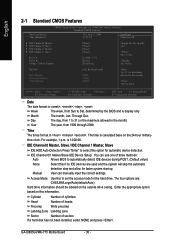
...) 1999 to automatically detect IDE devices during POST. (Default value) None Select this option for automatic device detection. You can manually input the correct settings. GA-8I865GVMK-775 Motherboard - 30 - Halt On Base Memory Extended Memory Total Memory [All, But Keyboard] 640K 239M 240M 1 to 31 (or maximum allowed in . IDE Channel 0/1 Master/Slave...
...) 1999 to automatically detect IDE devices during POST. (Default value) None Select this option for automatic device detection. You can manually input the correct settings. GA-8I865GVMK-775 Motherboard - 30 - Halt On Base Memory Extended Memory Total Memory [All, But Keyboard] 640K 239M 240M 1 to 31 (or maximum allowed in . IDE Channel 0/1 Master/Slave...


