Manual
Page 1
GA-8I865GVM-775/ GA-8I865GVMF-775 Intel® Pentium® 4 LGA775 Processor Motherboard User's Manual Rev. 1001 12ME-I865GVMT-1001
GA-8I865GVM-775/ GA-8I865GVMF-775 Intel® Pentium® 4 LGA775 Processor Motherboard User's Manual Rev. 1001 12ME-I865GVMT-1001

Manual
Page 2
Motherboard GA-8I865GVM-775/GA-8I865GVMF-775 Sep. 21, 2004 Motherboard GA-8I865GVM-775/ GA-8I865GVMF-775 Sep. 21, 2004
Motherboard GA-8I865GVM-775/GA-8I865GVMF-775 Sep. 21, 2004 Motherboard GA-8I865GVM-775/ GA-8I865GVMF-775 Sep. 21, 2004

Manual
Page 4
Table of Contents GA-8I865GVM-775/GA-8I865GVMF-775 Motherboard Layout 6 Block Diagram ...7 Chapter 1 Hardware Installation 9 1-1 Considerations Prior to Installation 9 1-2 Feature Summary 10 1-3 Installation of the CPU and Heatsink 11 1-3-1 Installation of the CPU ...
Table of Contents GA-8I865GVM-775/GA-8I865GVMF-775 Motherboard Layout 6 Block Diagram ...7 Chapter 1 Hardware Installation 9 1-1 Considerations Prior to Installation 9 1-2 Feature Summary 10 1-3 Installation of the CPU and Heatsink 11 1-3-1 Installation of the CPU ...
Manual
Page 6
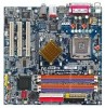
GA-8I865GVM-775/GA-8I865GVMF-775 Motherboard Layout KB_MS ATX_12V LGA 775 C PU _FAN ATX FDD IDE1 GA-8I865GVM-775 (or GA-8I865GVMF-775*) DDR1 DDR2 DDR3 DDR4 IDE2 VGA COMA LPT CLR_CMOS USB LAN F_AUDIO LPC47M997 R_U SB IR AU DIO SPDIF BIOS M arv ell 8001 C ODEC C D_ IN Intel 865GV BAT COMB PCI1 PCI2 TS B43A B23* PCI3 F2_1394* F1_1394* Intel IC H5 SATA 0 SATA 1 F_U SB1 F_U SB2 P WR_LE D F_PAN EL SYS_FAN * Only for GA-8I865GVMF-775. - 6 -
GA-8I865GVM-775/GA-8I865GVMF-775 Motherboard Layout KB_MS ATX_12V LGA 775 C PU _FAN ATX FDD IDE1 GA-8I865GVM-775 (or GA-8I865GVMF-775*) DDR1 DDR2 DDR3 DDR4 IDE2 VGA COMA LPT CLR_CMOS USB LAN F_AUDIO LPC47M997 R_U SB IR AU DIO SPDIF BIOS M arv ell 8001 C ODEC C D_ IN Intel 865GV BAT COMB PCI1 PCI2 TS B43A B23* PCI3 F2_1394* F1_1394* Intel IC H5 SATA 0 SATA 1 F_U SB1 F_U SB2 P WR_LE D F_PAN EL SYS_FAN * Only for GA-8I865GVMF-775. - 6 -

Manual
Page 7
Block Diagram LGA775 Processor CPUCLK+/-(133/200M Hz) 3 PCI PCICLK (33M Hz) MIC Line-Out Line-In Ho st VGA Interfa ce DDR 400/333/266MHz DIMM In te l 865GV GMCH PCI Bus In te l ICH5 TSB43AB23* M arvell 8001 Dual Channel Memory HCLK (133/200MHz) GM CHCLK (66M Hz) 66MHz 33MHz 14.318M Hz 48MHz BIOS 2 Serial ATA ATA33/66/100 IDE Channels RJ45 3 IEEE1394* CODEC LPC47M 997 Floppy LPT Port COM Port 8 USB Ports PS/2 KB/Mouse 14.318M Hz 33MHz * Only for GA-8I865GVMF-775. - 7 -
Block Diagram LGA775 Processor CPUCLK+/-(133/200M Hz) 3 PCI PCICLK (33M Hz) MIC Line-Out Line-In Ho st VGA Interfa ce DDR 400/333/266MHz DIMM In te l 865GV GMCH PCI Bus In te l ICH5 TSB43AB23* M arvell 8001 Dual Channel Memory HCLK (133/200MHz) GM CHCLK (66M Hz) 66MHz 33MHz 14.318M Hz 48MHz BIOS 2 Serial ATA ATA33/66/100 IDE Channels RJ45 3 IEEE1394* CODEC LPC47M 997 Floppy LPT Port COM Port 8 USB Ports PS/2 KB/Mouse 14.318M Hz 33MHz * Only for GA-8I865GVMF-775. - 7 -
Manual
Page 10
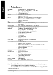
GA-8I865GVM(F)-775 Motherboard - 10 - MIC (Center/Subwoofer Speaker Out) w SPDIF Out connection w CD In connection w SMSC LPC47M997 w System voltage detection w CPU / System temperature detection w CPU / System fan ... set Mem ory Slo ts IDE Connections FDD Connections Onboard SATA Peripherals Onboard LAN Onboard Audio I/O Control Hardware Monitor BIOS Additional Features Form Factor w GA-8I865GVM-775 or GA-8I865GVMF-775 w Supports the latest Intel® Pentium® 4 LGA775 CPU w Supports 800/533MHz FSB w L2 cache varies with CPU w Northbridge: Intel® 865GV Chipset w Southbridge...
GA-8I865GVM(F)-775 Motherboard - 10 - MIC (Center/Subwoofer Speaker Out) w SPDIF Out connection w CD In connection w SMSC LPC47M997 w System voltage detection w CPU / System temperature detection w CPU / System fan ... set Mem ory Slo ts IDE Connections FDD Connections Onboard SATA Peripherals Onboard LAN Onboard Audio I/O Control Hardware Monitor BIOS Additional Features Form Factor w GA-8I865GVM-775 or GA-8I865GVMF-775 w Supports the latest Intel® Pentium® 4 LGA775 CPU w Supports 800/533MHz FSB w L2 cache varies with CPU w Northbridge: Intel® 865GV Chipset w Southbridge...
Manual
Page 12
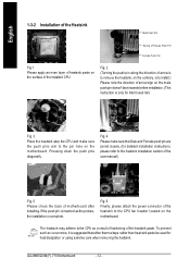
... the heatsink installation section of the user manual) Fig. 5 Please check the back of the heatsink to the CPU fan header located on the m otherboard. GA-8I865GVM(F)-775 Motherboard - 12 - Fig. 4 Please make sure the Male and Female push pin are joined closely. (for heat dissipation or using extreme care when removing the...
... the heatsink installation section of the user manual) Fig. 5 Please check the back of the heatsink to the CPU fan header located on the m otherboard. GA-8I865GVM(F)-775 Motherboard - 12 - Fig. 4 Please make sure the Male and Female push pin are joined closely. (for heat dissipation or using extreme care when removing the...

Manual
Page 14
... storage capacity in order to operate the Dual Channel Technology, please note the following table is for BIOS to detect all the DDR memory modules. GA-8I865GVM(F)-775 includes 4 DIMM sockets, and each Channel has two DIMM sockets as following: Channel A : DDR 1, DDR 2 Channel B : DDR 3, DDR 4 If you want to... 4 m em ory m odules DDR 1 DS/SS X DS/SS DDR 2 X DS/SS DS/SS DDR 3 DS/SS X DS/SS DDR 4 X DS/SS DS/SS GA-8I865GVM(F)-775 Motherboard - 14 - After operating the Dual Channel Technology, the bandwidth of Memory Bus will add double up to work. Dual channel memory cannot function if...
... storage capacity in order to operate the Dual Channel Technology, please note the following table is for BIOS to detect all the DDR memory modules. GA-8I865GVM(F)-775 includes 4 DIMM sockets, and each Channel has two DIMM sockets as following: Channel A : DDR 1, DDR 2 Channel B : DDR 3, DDR 4 If you want to... 4 m em ory m odules DDR 1 DS/SS X DS/SS DDR 2 X DS/SS DS/SS DDR 3 DS/SS X DS/SS DDR 4 X DS/SS DS/SS GA-8I865GVM(F)-775 Motherboard - 14 - After operating the Dual Channel Technology, the bandwidth of Memory Bus will add double up to work. Dual channel memory cannot function if...

Manual
Page 16
... transfer speeds of a printer, scanner and other peripheral devices. Also make sure your OS or device(s) vendors. Line In Devices like CD-ROM, walkman etc. GA-8I865GVM(F)-775 Motherboard - 16 - USB port Before you connect your device(s) into USB connector(s), please make sure your OS does not support USB controller, please contact OS...
... transfer speeds of a printer, scanner and other peripheral devices. Also make sure your OS or device(s) vendors. Line In Devices like CD-ROM, walkman etc. GA-8I865GVM(F)-775 Motherboard - 16 - USB port Before you connect your device(s) into USB connector(s), please make sure your OS does not support USB controller, please contact OS...

Manual
Page 17
Hardware Installation English 1-7 Connectors Introduction 1 3 2 5 17 6 11 13 9 18 4 7 8 12 16 15 14 10 1) ATX_12V 2) ATX (Power Connector) 3) CPU_FAN 4) SYS_FAN 5) FDD 6) IDE1 / IDE2 7) SATA0 / SATA1 8) PWR_LED 9) BAT 10) F_PANEL 11) F_AUDIO 12) CD_IN 13) SPDIF 14) F_USB1 / F_USB2 15) F1_1394* / F2_1394* 16) COMB 17) IR 18) CLR_CMOS * Only for GA-8I865GVMF-775. - 17 -
Hardware Installation English 1-7 Connectors Introduction 1 3 2 5 17 6 11 13 9 18 4 7 8 12 16 15 14 10 1) ATX_12V 2) ATX (Power Connector) 3) CPU_FAN 4) SYS_FAN 5) FDD 6) IDE1 / IDE2 7) SATA0 / SATA1 8) PWR_LED 9) BAT 10) F_PANEL 11) F_AUDIO 12) CD_IN 13) SPDIF 14) F_USB1 / F_USB2 15) F1_1394* / F2_1394* 16) COMB 17) IR 18) CLR_CMOS * Only for GA-8I865GVMF-775. - 17 -
Manual
Page 18
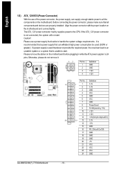
... 13 3.3V 14 -12V 15 GND 16 PS_ON(softOn/Off) 17 GND 18 GND 19 GND 20 -5 V 21 VCC 22 VCC 23 VCC 24 GND GA-8I865GVM(F)-775 Motherboard - 18 - Align the power connector with its proper location on the motherboard before plugging in while theATX power supplier is recommended that a power supply...
... 13 3.3V 14 -12V 15 GND 16 PS_ON(softOn/Off) 17 GND 18 GND 19 GND 20 -5 V 21 VCC 22 VCC 23 VCC 24 GND GA-8I865GVM(F)-775 Motherboard - 18 - Align the power connector with its proper location on the motherboard before plugging in while theATX power supplier is recommended that a power supply...
Manual
Page 20
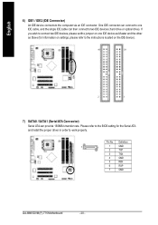
Definition 7 1 1 GND 2 TXP 3 TXN 4 GND 5 RXN 6 RXP 7 GND GA-8I865GVM(F)-775 Motherboard - 20 - If you wish to connect two IDE devices, please set the jumper on one IDE cable, and the single IDE cable can then ...
Definition 7 1 1 GND 2 TXP 3 TXN 4 GND 5 RXN 6 RXP 7 GND GA-8I865GVM(F)-775 Motherboard - 20 - If you wish to connect two IDE devices, please set the jumper on one IDE cable, and the single IDE cable can then ...
Manual
Page 22
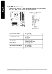
.... Pin 3: NC Pin 4: Data(-) Open:Normal Operation Close: Reset Hardware System Open:Normal Operation Close:Power On/Off Pin 1: LED anode(+) Pin 2: LED cathode(-) NC GA-8I865GVM(F)-775 Motherboard - 22 - Me ssa ge LED/ Po we r/ Sle ep L ED Spe aker C onnector Pow er Sw itch MSG+ MSG- RESRES+ NC Re set Switch...
.... Pin 3: NC Pin 4: Data(-) Open:Normal Operation Close: Reset Hardware System Open:Normal Operation Close:Power On/Off Pin 1: LED anode(+) Pin 2: LED cathode(-) NC GA-8I865GVM(F)-775 Motherboard - 22 - Me ssa ge LED/ Po we r/ Sle ep L ED Spe aker C onnector Pow er Sw itch MSG+ MSG- RESRES+ NC Re set Switch...
Manual
Page 24
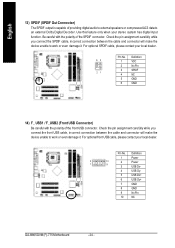
... polarity of the SPDIF connector. Pin No. Definition 1 Power 2 1 10 2 Power 9 3 USB Dx- 4 USB Dy- 5 USB Dx+ 6 USB Dy+ 7 GND 8 GND 9 No Pin 10 NC GA-8I865GVM(F)-775 Motherboard - 24 - Check the pin assignment carefully while you connect the front USB cable, incorrect connection between the cable and connector will make the device...
... polarity of the SPDIF connector. Pin No. Definition 1 Power 2 1 10 2 Power 9 3 USB Dx- 4 USB Dy- 5 USB Dx+ 6 USB Dy+ 7 GND 8 GND 9 No Pin 10 NC GA-8I865GVM(F)-775 Motherboard - 24 - Check the pin assignment carefully while you connect the front USB cable, incorrect connection between the cable and connector will make the device...

Manual
Page 25
... cable, please contact your local dealer. Definition 1 NDCDB- 2 NSINB 2 10 3 NSOUTB 1 9 4 NDTRB- 5 GND 6 NDSRB- 7 NRT SB- 8 NCT SB- 9 NRIB- 10 No Pin * Only for GA-8I865GVMF-775. - 25 - Check the pin assignm ent carefully while you connect the IEEE1394 cable, incorrect connection between the cable and connector will make the device unable...
... cable, please contact your local dealer. Definition 1 NDCDB- 2 NSINB 2 10 3 NSOUTB 1 9 4 NDTRB- 5 GND 6 NDSRB- 7 NRT SB- 8 NCT SB- 9 NRIB- 10 No Pin * Only for GA-8I865GVMF-775. - 25 - Check the pin assignm ent carefully while you connect the IEEE1394 cable, incorrect connection between the cable and connector will make the device unable...
Manual
Page 26
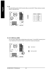
Please contact your nearest dealer for optional IR device. Pin No. Definition 1 VCC 2 No Pin 3 IR RX 1 4 GND 5 IR TX 18) CLR_CMOS (Clear CMOS) You m ay clear the CMOS data to prevent from improper use this jumper. Open:Normal 1 Short:Clear CMOS 1 GA-8I865GVM(F)-775 Motherboard - 26 - To clear CMOS, temporarily short 1-2 pin. English 17) IR Be careful with the polarity of the IR connector while you connect the IR. Default doesn't include the "Shunter" to its default values by this jumper.
Please contact your nearest dealer for optional IR device. Pin No. Definition 1 VCC 2 No Pin 3 IR RX 1 4 GND 5 IR TX 18) CLR_CMOS (Clear CMOS) You m ay clear the CMOS data to prevent from improper use this jumper. Open:Normal 1 Short:Clear CMOS 1 GA-8I865GVM(F)-775 Motherboard - 26 - To clear CMOS, temporarily short 1-2 pin. English 17) IR Be careful with the polarity of the IR connector while you connect the IR. Default doesn't include the "Shunter" to its default values by this jumper.
Manual
Page 28
... Status This setup page is control CPU clock and frequency ratio. n Load Fail -Safe Defaults Fail-Safe Defaults indicates the v alue of Green function features. GA-8I865GVM(F)- 775 Motherboard - 28 -
... Status This setup page is control CPU clock and frequency ratio. n Load Fail -Safe Defaults Fail-Safe Defaults indicates the v alue of Green function features. GA-8I865GVM(F)- 775 Motherboard - 28 -
Manual
Page 30
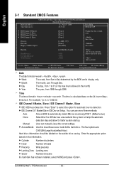
... Landing zone Sector Numberof sectors If a hard disk has not been installed, select NONEand press . Enter the appropriate option based on the 24-hour military - GA-8I865GVM(F)- 775 Motherboard - 30 - Jan. Through Dec. is display only Month The month, Jan. IDE Channel 0 Master, Sl ave / IDE Channel 1 Master, Slave IDE HDD Auto-Detec...
... Landing zone Sector Numberof sectors If a hard disk has not been installed, select NONEand press . Enter the appropriate option based on the 24-hour military - GA-8I865GVM(F)- 775 Motherboard - 30 - Jan. Through Dec. is display only Month The month, Jan. IDE Channel 0 Master, Sl ave / IDE Channel 1 Master, Slave IDE HDD Auto-Detec...
Manual
Page 32
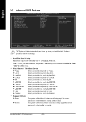
... list. LS120 Selecty our boot dev ice priority by USB-ZIP. First / Second / Third Boot Device Floppy Select y our boot dev ice priority by HardDisk. GA-8I865GVM(F)- 775 Motherboard - 32 - Hard Disk Selecty our bootdev ice priority by Floppy . CDROM Selecty our bootdev ice priority by ZIP. English 2-2 Advanced BIOS Features CMOS Setup...
... list. LS120 Selecty our boot dev ice priority by USB-ZIP. First / Second / Third Boot Device Floppy Select y our boot dev ice priority by HardDisk. GA-8I865GVM(F)- 775 Motherboard - 32 - Hard Disk Selecty our bootdev ice priority by Floppy . CDROM Selecty our bootdev ice priority by ZIP. English 2-2 Advanced BIOS Features CMOS Setup...

Manual
Page 34
GA-8I865GVM(F)- 775 Motherboard - 34 - Au to When there is no dev ice to be plugged in IDE1 or IDE2, SATA controller w ill remap to IDE controller. (Default v ... Primary PCI IDE On-Chip Secon dary PCI IDE On-Chip SATA x SATA P ort0 config ure as SATA P ort1 config ure as " item. * Only for GA-8I865GVMF-775.
GA-8I865GVM(F)- 775 Motherboard - 34 - Au to When there is no dev ice to be plugged in IDE1 or IDE2, SATA controller w ill remap to IDE controller. (Default v ... Primary PCI IDE On-Chip Secon dary PCI IDE On-Chip SATA x SATA P ort0 config ure as SATA P ort1 config ure as " item. * Only for GA-8I865GVMF-775.


