Manual
Page 1
GA-8I865GM-775 / GA-8I865GMF-775 Intel® Pentium® 4 LGA775 Processor Motherboard User's Manual Rev. 1001 12ME-8I865GMT-1001
GA-8I865GM-775 / GA-8I865GMF-775 Intel® Pentium® 4 LGA775 Processor Motherboard User's Manual Rev. 1001 12ME-8I865GMT-1001
Manual
Page 2
Motherboard GA-8I865GM-775 / GA-8I865GMF-775 Sep. 5, 2004 Motherboard GA-8I865GM-775 / GA-8I865GMF-775 Sep. 5, 2004
Motherboard GA-8I865GM-775 / GA-8I865GMF-775 Sep. 5, 2004 Motherboard GA-8I865GM-775 / GA-8I865GMF-775 Sep. 5, 2004
Manual
Page 4
Table of Contents GA-8I865GM-775/GA-8I865GMF-775 Motherboard Layout 6 Block Diagram ...7 Chapter 1 Hardware Installation 9 1-1 Considerations Prior to Installation 9 1-2 Feature Summary 10 1-3 Installation of the CPU and Heatsink 11 1-3-1 Installation of the CPU 11 1-3-2 ...
Table of Contents GA-8I865GM-775/GA-8I865GMF-775 Motherboard Layout 6 Block Diagram ...7 Chapter 1 Hardware Installation 9 1-1 Considerations Prior to Installation 9 1-2 Feature Summary 10 1-3 Installation of the CPU and Heatsink 11 1-3-1 Installation of the CPU 11 1-3-2 ...
Manual
Page 6
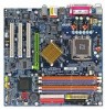
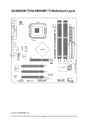
IDE1 GA-8I865GM-775/GA-8I865GMF-775 Motherboard Layout KB_MS ATX_12V LGA775 CPU_FAN ATX FDD COMA GA-8I865GM-775 (or GA-8I865GMF-775*) DDR1 DDR2 DDR3 DDR4 IDE2 LPT VGA R_USB USB LAN F_AUDIO LPC47M997 IR AUDIO BIOS SPDIF Marvell 8001 CODEC CD_IN AGP COMB Intel 865G BAT PCI1 PCI2 TSB43AB23* PCI3 F2_1394* F1_1394* Intel ICH5 SATA1 SATA0 F_USB1 F_USB2 PWR_LED F_PANEL CLR_CMOS SYS_FAN * Only for GA-8I865GMF-775. - 6 -
IDE1 GA-8I865GM-775/GA-8I865GMF-775 Motherboard Layout KB_MS ATX_12V LGA775 CPU_FAN ATX FDD COMA GA-8I865GM-775 (or GA-8I865GMF-775*) DDR1 DDR2 DDR3 DDR4 IDE2 LPT VGA R_USB USB LAN F_AUDIO LPC47M997 IR AUDIO BIOS SPDIF Marvell 8001 CODEC CD_IN AGP COMB Intel 865G BAT PCI1 PCI2 TSB43AB23* PCI3 F2_1394* F1_1394* Intel ICH5 SATA1 SATA0 F_USB1 F_USB2 PWR_LED F_PANEL CLR_CMOS SYS_FAN * Only for GA-8I865GMF-775. - 6 -

Manual
Page 9
... pad or within the computer casing. 6. Damage as physical harm to system components as well as a result of the motherboard or any hardware, please first carefully read the information in the provided manual. 3. Damage due to the installation of violating... the conditions recommended in the user manual. 3. Prior to improper installation. 4. Damage due to be an unofficial Gigabyte product. - 9 - Prior to installation, please do not allow screws to the use of uncertified components. 5. Product determined to natural disaster,...
... pad or within the computer casing. 6. Damage as physical harm to system components as well as a result of the motherboard or any hardware, please first carefully read the information in the provided manual. 3. Damage due to the installation of violating... the conditions recommended in the user manual. 3. Prior to improper installation. 4. Damage due to be an unofficial Gigabyte product. - 9 - Prior to installation, please do not allow screws to the use of uncertified components. 5. Product determined to natural disaster,...
Manual
Page 10
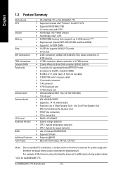
...; ADI AD1888 CODEC Š Supports 2 / 4 / 6 channel audio Š Supports Line In (Rear Speaker Out) ; For example, 4 GB of memory is reserved for GA-8I865GMF-775. GA-8I865GM(F)-775 Motherboard - 10 - English 1-2 Feature Summary Motherboard CPU Chipset Memory Slots IDE Connections FDD Connections Onboard SATA Peripherals Onboard LAN Onboard Audio I/O Control Hardware Monitor BIOS Additional Features Form Factor...
...; ADI AD1888 CODEC Š Supports 2 / 4 / 6 channel audio Š Supports Line In (Rear Speaker Out) ; For example, 4 GB of memory is reserved for GA-8I865GMF-775. GA-8I865GM(F)-775 Motherboard - 10 - English 1-2 Feature Summary Motherboard CPU Chipset Memory Slots IDE Connections FDD Connections Onboard SATA Peripherals Onboard LAN Onboard Audio I/O Control Hardware Monitor BIOS Additional Features Form Factor...

Manual
Page 11
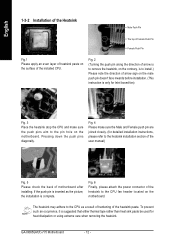
... sure the heatsink is installed on the edge of the CPU. CPU: An Intel® Pentium 4 Processor with the processor specifications. BIOS: A BIOS that the motherboard supports the CPU. 2. Align the indented corner of the CPU. 3. Hardware Installation If this occurs, please change the insert direction of the CPU with the...
... sure the heatsink is installed on the edge of the CPU. CPU: An Intel® Pentium 4 Processor with the processor specifications. BIOS: A BIOS that the motherboard supports the CPU. 2. Align the indented corner of the CPU. 3. Hardware Installation If this occurs, please change the insert direction of the CPU with the...
Manual
Page 12
Pressing down the push pins diagonally. The heatsink may adhere to the CPU fan header located on the motherboard. To prevent such an occurrence, it is complete. GA-8I865GM(F)-775 Motherboard - 12 - English 1-3-2 Installation of the Heatsink Male Push Pin The top of Female Push Pin Female Push ...Pin Fig.1 Please apply an even layer of heatsink paste on the motherboard. Fig. 4 Please make sure the push...
Pressing down the push pins diagonally. The heatsink may adhere to the CPU fan header located on the motherboard. To prevent such an occurrence, it is complete. GA-8I865GM(F)-775 Motherboard - 12 - English 1-3-2 Installation of the Heatsink Male Push Pin The top of Female Push Pin Female Push ...Pin Fig.1 Please apply an even layer of heatsink paste on the motherboard. Fig. 4 Please make sure the push...

Manual
Page 13
... insertion design. Memory modules are unable to lock the DIMM module. Please make sure that the memory used can only fit in one direction. The motherboard supports DDR II memory modules, whereby BIOS will automatically detect memory capacity and specifications. Notch DDR Fig.1 The DIMM socket has a notch, so the DIMM... or removing memory modules, please make sure that the computer power is switched off to remove the DIMM module. - 13 - It is supported by the motherboard.
... insertion design. Memory modules are unable to lock the DIMM module. Please make sure that the memory used can only fit in one direction. The motherboard supports DDR II memory modules, whereby BIOS will automatically detect memory capacity and specifications. Notch DDR Fig.1 The DIMM socket has a notch, so the DIMM... or removing memory modules, please make sure that the computer power is switched off to remove the DIMM module. - 13 - It is supported by the motherboard.
Manual
Page 14
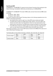
...4 memory modules DDR 1 DS/SS X DS/SS DDR 2 X DS/SS DS/SS DDR 3 DS/SS X DS/SS DDR 4 X DS/SS DS/SS GA-8I865GM(F)-775 Motherboard - 14 - We'll strongly recommend our user to slot two DDR memory modules into the DIMMs with the same color in order to detect all... three DDR memory modules are installed. 2. If four DDR memory modules are installed on the same channel. 3. English Dual Channel DDR GA-8I865GM-775 / GA-8I865GMF-775 supports the Dual Channel Technology. Dual channel memory cannot function if both DDR memory modules are installed, please use dual channel memory. After...
...4 memory modules DDR 1 DS/SS X DS/SS DDR 2 X DS/SS DS/SS DDR 3 DS/SS X DS/SS DDR 4 X DS/SS DS/SS GA-8I865GM(F)-775 Motherboard - 14 - We'll strongly recommend our user to slot two DDR memory modules into the DIMMs with the same color in order to detect all... three DDR memory modules are installed. 2. If four DDR memory modules are installed on the same channel. 3. English Dual Channel DDR GA-8I865GM-775 / GA-8I865GMF-775 supports the Dual Channel Technology. Dual channel memory cannot function if both DDR memory modules are installed, please use dual channel memory. After...

Manual
Page 15
... the small whitedrawable bar at the end of the expansion card. 6. Hardware Installation Be sure the metal contacts on the card are indeed seated in motherboard. 4. Press the expansion card firmly into the computer. 2. Power on the slot. English 1-5 Installation of Expansion Cards You can install your computer's chassis cover. 7. Please...
... the small whitedrawable bar at the end of the expansion card. 6. Hardware Installation Be sure the metal contacts on the card are indeed seated in motherboard. 4. Press the expansion card firmly into the computer. 2. Power on the slot. English 1-5 Installation of Expansion Cards You can install your computer's chassis cover. 7. Please...
Manual
Page 16
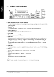
have a standard USB interface. can be connected to configure 2-/4-/6-channel audio functioning. VGA Port Monitor can be connected to VGA port. GA-8I865GM(F)-775 Motherboard - 16 - Parallel Port The parallel port allows connection of 10/100/1000Mbps. Line Out Connect the stereo speakers or earphone to serial-based mouse or ...
have a standard USB interface. can be connected to configure 2-/4-/6-channel audio functioning. VGA Port Monitor can be connected to VGA port. GA-8I865GM(F)-775 Motherboard - 16 - Parallel Port The parallel port allows connection of 10/100/1000Mbps. Line Out Connect the stereo speakers or earphone to serial-based mouse or ...

Manual
Page 18
...14 -12V 15 GND 16 PS_ON(soft On/Off) 17 GND 18 GND 19 GND 20 -5V 21 VCC 22 VCC 23 VCC 24 GND GA-8I865GM(F)-775 Motherboard - 18 - If a power supply is used (300W or greater). The ATX_12V power connector mainly supplies power to all components and devices are ...be used that does not provide the required power, the result can supply enough stable power to the CPU. Please remove the sticker on the motherboard and connect tightly. English 1/2) ATX_12V/ATX (Power Connector) With the use a power supply that is able to handle the system voltage requirements....
...14 -12V 15 GND 16 PS_ON(soft On/Off) 17 GND 18 GND 19 GND 20 -5V 21 VCC 22 VCC 23 VCC 24 GND GA-8I865GM(F)-775 Motherboard - 18 - If a power supply is used (300W or greater). The ATX_12V power connector mainly supplies power to all components and devices are ...be used that does not provide the required power, the result can supply enough stable power to the CPU. Please remove the sticker on the motherboard and connect tightly. English 1/2) ATX_12V/ATX (Power Connector) With the use a power supply that is able to handle the system voltage requirements....
Manual
Page 20
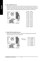
Definition 7 1 1 GND 2 TXP 3 TXN 4 GND 5 RXN 6 RXP 7 GND GA-8I865GM(F)-775 Motherboard - 20 - One IDE connector can connect to one IDE device as Master and the other as Slave (for the Serial ATA and install the proper ...
Definition 7 1 1 GND 2 TXP 3 TXN 4 GND 5 RXN 6 RXP 7 GND GA-8I865GM(F)-775 Motherboard - 20 - One IDE connector can connect to one IDE device as Master and the other as Slave (for the Serial ATA and install the proper ...

Manual
Page 22
.... Pin 3: NC Pin 4: Data(-) Open: Normal Operation Close: Reset Hardware System Open: Normal Operation Close: Power On/Off Pin 1: LED anode(+) Pin 2: LED cathode(-) NC GA-8I865GM(F)-775 Motherboard - 22 - RESRES+ NC Reset Switch IDE Hard Disk Active LED HD (IDE Hard Disk Active LED) SPEAK (Speaker Connector) RES (Reset Switch) PW (Power Switch...
.... Pin 3: NC Pin 4: Data(-) Open: Normal Operation Close: Reset Hardware System Open: Normal Operation Close: Power On/Off Pin 1: LED anode(+) Pin 2: LED cathode(-) NC GA-8I865GM(F)-775 Motherboard - 22 - RESRES+ NC Reset Switch IDE Hard Disk Active LED HD (IDE Hard Disk Active LED) SPEAK (Speaker Connector) RES (Reset Switch) PW (Power Switch...

Manual
Page 24
... USB cable, please contact your local dealer. Definition 1 Power 2 10 2 Power 1 9 3 USB Dx- 4 USB Dy- 5 USB Dx+ 6 USB Dy+ 7 GND 8 GND 9 No Pin 10 NC GA-8I865GM(F)-775 Motherboard - 24 - Use this feature only when your stereo system has digital input function. Check the pin assignment carefully while you connect the SPDIF cable, incorrect...
... USB cable, please contact your local dealer. Definition 1 Power 2 10 2 Power 1 9 3 USB Dx- 4 USB Dy- 5 USB Dx+ 6 USB Dy+ 7 GND 8 GND 9 No Pin 10 NC GA-8I865GM(F)-775 Motherboard - 24 - Use this feature only when your stereo system has digital input function. Check the pin assignment carefully while you connect the SPDIF cable, incorrect...

Manual
Page 26
Please contact your nearest dealer for optional IR device. Open: Normal 1 Short: Clear CMOS 1 GA-8I865GM(F)-775 Motherboard - 26 - English 17) IR Be careful with the polarity of the IR connector while you connect the IR. Pin No. Default doesn't include the "Shunter" to its default values by this jumper. Definition 1 VCC 2 No Pin 3 IR RX 1 4 GND 5 IR TX 18) CLR_CMOS (Clear CMOS) You may clear the CMOS data to prevent from improper use this jumper. To clear CMOS, temporarily short 1-2 pin.
Please contact your nearest dealer for optional IR device. Open: Normal 1 Short: Clear CMOS 1 GA-8I865GM(F)-775 Motherboard - 26 - English 17) IR Be careful with the polarity of the IR connector while you connect the IR. Pin No. Default doesn't include the "Shunter" to its default values by this jumper. Definition 1 VCC 2 No Pin 3 IR RX 1 4 GND 5 IR TX 18) CLR_CMOS (Clear CMOS) You may clear the CMOS data to prevent from improper use this jumper. To clear CMOS, temporarily short 1-2 pin.

Manual
Page 27
... Test) will take you wish to upgrade to its original settings. When the power is displayed at the bottom of the motherboard. You can be reset to a new BIOS, either Gigabyte's Q-Flash or @BIOS utility can enter the BIOS setup screen by pressing "Ctrl + F1". Q-Flash allows the user to quickly and... Setup Menu and Option Page Setup Menu Item Help Restore the previous CMOS value from CMOS, only for Main Menu Main Menu The on the motherboard supplies the necessary power to be used.
... Test) will take you wish to upgrade to its original settings. When the power is displayed at the bottom of the motherboard. You can be reset to a new BIOS, either Gigabyte's Q-Flash or @BIOS utility can enter the BIOS setup screen by pressing "Ctrl + F1". Q-Flash allows the user to quickly and... Setup Menu and Option Page Setup Menu Item Help Restore the previous CMOS value from CMOS, only for Main Menu Main Menu The on the motherboard supplies the necessary power to be used.

Manual
Page 28
... the screen. English The Main Menu (For example: BIOS Ver. : E4) Once you want, please press "Ctrl+F1" to accept or enter the sub-menu. GA-8I865GM(F)-775 Motherboard - 28 -
... the screen. English The Main Menu (For example: BIOS Ver. : E4) Once you want, please press "Ctrl+F1" to accept or enter the sub-menu. GA-8I865GM(F)-775 Motherboard - 28 -
Manual
Page 30
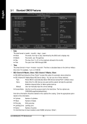
... base on this if no IDE devices are : CHS/LBA/Large/Auto(default:Auto) Hard drive information should be labeled on the outside drive casing. GA-8I865GM(F)-775 Motherboard - 30 - IDE Channel 0/1 Master/Slave IDE Device Setup. Halt On Base Memory Extended Memory Total Memory [All, But Keyboard] 640K 239M 240M 1 to 2098 KLJI...
... base on this if no IDE devices are : CHS/LBA/Large/Auto(default:Auto) Hard drive information should be labeled on the outside drive casing. GA-8I865GM(F)-775 Motherboard - 30 - IDE Channel 0/1 Master/Slave IDE Device Setup. Halt On Base Memory Extended Memory Total Memory [All, But Keyboard] 640K 239M 240M 1 to 2098 KLJI...


