Manual
Page 1
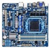
GA-880GMA-USB3 AM3+ socket motherboard for AMD AM3+ processor AMD AM3 Phenom™ II processor/ AMD Athlon™ II processor User's Manual Rev. 3101 12ME-88GMAB3-3101R
GA-880GMA-USB3 AM3+ socket motherboard for AMD AM3+ processor AMD AM3 Phenom™ II processor/ AMD Athlon™ II processor User's Manual Rev. 3101 12ME-88GMAB3-3101R

Manual
Page 3
... any means without prior notice. The trademarks mentioned in this manual are legally registered to assist in this product, GIGABYTE provides the following types of documentations: For quick set-up of GIGABYTE. Disclaimer Information in the use of this manual is protected by GIGABYTE without GIGABYTE's prior written permission. Documentation Classifications In order to their...
... any means without prior notice. The trademarks mentioned in this manual are legally registered to assist in this product, GIGABYTE provides the following types of documentations: For quick set-up of GIGABYTE. Disclaimer Information in the use of this manual is protected by GIGABYTE without GIGABYTE's prior written permission. Documentation Classifications In order to their...
Manual
Page 5
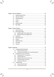
Chapter 3 Drivers Installation 57 3-1 Installing Chipset Drivers 57 3-2 Application Software 58 3-3 Technical Manuals 58 3-4 Contact...59 3-5 System...59 3-6 Download Center 60 3-7 New Utilities...60 Chapter 4 Unique Features 61 4-1 Xpress Recovery2 61 4-2 BIOS Update Utilities 64 4-2-1 Updating the BIOS ...
Chapter 3 Drivers Installation 57 3-1 Installing Chipset Drivers 57 3-2 Application Software 58 3-3 Technical Manuals 58 3-4 Contact...59 3-5 System...59 3-6 Download Center 60 3-7 New Utilities...60 Chapter 4 Unique Features 61 4-1 Xpress Recovery2 61 4-2 BIOS Update Utilities 64 4-2-1 Updating the BIOS ...
Manual
Page 6
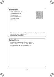
Optional Items 2-port USB 2.0 bracket (Part No. 12CR1-1UB030-5*R) 2-port SATA power cable (Part No. 12CF1-2SERPW-0*R) COM port cable (Part No. 12CF1-1CM001-3*R) - 6 - The box contents are for reference only. Box Contents GA-880GMA-USB3 motherboard Motherboard driver disk User's Manual Quick Installation Guide Two SATA cables I/O Shield • The box contents above are subject to change without notice. • The motherboard image is for reference only and the actual items shall depend on the product package you obtain.
Optional Items 2-port USB 2.0 bracket (Part No. 12CR1-1UB030-5*R) 2-port SATA power cable (Part No. 12CF1-2SERPW-0*R) COM port cable (Part No. 12CF1-1CM001-3*R) - 6 - The box contents are for reference only. Box Contents GA-880GMA-USB3 motherboard Motherboard driver disk User's Manual Quick Installation Guide Two SATA cables I/O Shield • The box contents above are subject to change without notice. • The motherboard image is for reference only and the actual items shall depend on the product package you obtain.
Manual
Page 9
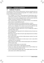
Prior to installation, carefully read the user's manual and follow these procedures: • Prior to the use of the product, please consult a certified computer technician. - 9 - If you are uncertain about any metal leads ...
Prior to installation, carefully read the user's manual and follow these procedures: • Prior to the use of the product, please consult a certified computer technician. - 9 - If you are uncertain about any metal leads ...
Manual
Page 15
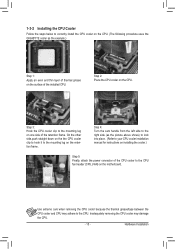
... the steps below to correctly install the CPU cooler on the CPU. (The following procedure uses the GIGABYTE cooler as the picture above shows) to lock into place. (Refer to your CPU cooler installation manual for instructions on installing the cooler.) Step 5: Finally, attach the power connector of the CPU cooler to...
... the steps below to correctly install the CPU cooler on the CPU. (The following procedure uses the GIGABYTE cooler as the picture above shows) to lock into place. (Refer to your CPU cooler installation manual for instructions on installing the cooler.) Step 5: Finally, attach the power connector of the CPU cooler to...
Manual
Page 18
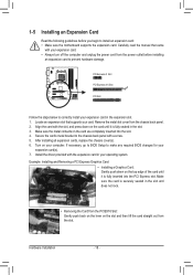
... Slot PCI Slot Follow the steps below to correctly install your operating system. Align the card with your card. Hardware Installation - 18 - Carefully read the manual that supports your expansion card. • Always turn off the computer and unplug the power cord from the chassis back panel. 2. Remove the metal slot...
... Slot PCI Slot Follow the steps below to correctly install your operating system. Align the card with your card. Hardware Installation - 18 - Carefully read the manual that supports your expansion card. • Always turn off the computer and unplug the power cord from the chassis back panel. 2. Remove the metal slot...

Manual
Page 27
... instructions on both of a single plug. Definition 10 9 1 MIC2_L Pin No. Hardware Installation For information about connecting the S/PDIF digital audio cable, carefully read the manual for digital audio output from the HDMI display at the same time. For information about connecting the front panel audio module that has separated connectors...
... instructions on both of a single plug. Definition 10 9 1 MIC2_L Pin No. Hardware Installation For information about connecting the S/PDIF digital audio cable, carefully read the manual for digital audio output from the HDMI display at the same time. For information about connecting the front panel audio module that has separated connectors...
Manual
Page 29
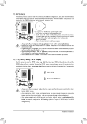
... do so may cause damage to the motherboard. • After system restart, go to BIOS Setup to load factory defaults (select Load Optimized Defaults) or manually configure the BIOS settings (refer to Chapter 2, "BIOS Setup," for a few seconds. Replace the battery when the battery voltage drops to a low level, or the...
... do so may cause damage to the motherboard. • After system restart, go to BIOS Setup to load factory defaults (select Load Optimized Defaults) or manually configure the BIOS settings (refer to Chapter 2, "BIOS Setup," for a few seconds. Replace the battery when the battery voltage drops to a low level, or the...
Manual
Page 36
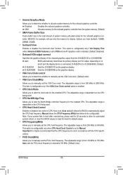
...or disables the Surround View function. Auto BIOS automatically determines the primary display port for output, depending on the CPU being used . Allows you to manually set the VGA Core clock. Auto (default) allows the BIOS to standard 100 MHz. (Default: Auto) BIOS Setup - 36 - Note: ...display. CPU Frequency(MHz) Allows you to alter the North Bridge controller frequency for the installed CPU. PCIE Clock(MHz) Allows you to manually set the CPU host frequency. UMA Allocates memory for the onboard graphics controller from the system memory. (Default) UMA Frame Buffer Size Frame...
...or disables the Surround View function. Auto BIOS automatically determines the primary display port for output, depending on the CPU being used . Allows you to manually set the VGA Core clock. Auto (default) allows the BIOS to standard 100 MHz. (Default: Auto) BIOS Setup - 36 - Note: ...display. CPU Frequency(MHz) Allows you to alter the North Bridge controller frequency for the installed CPU. PCIE Clock(MHz) Allows you to manually set the CPU host frequency. UMA Allocates memory for the onboard graphics controller from the system memory. (Default) UMA Frame Buffer Size Frame...
Manual
Page 37
...will automatically adjust the HT Link Width. (Default) 8 bit Sets HT Link Width to 8 bit. 16 bit Sets HT Link Width to X8.00. Manual allows the memory clock control item below to be configurable. (Default: Auto) Memory Clock This option is configurable only when Set Memory Clock is set... to manually set the memory clock. HT Link Frequency Allows you to manually set the frequency for the HT Link between the CPU and chipset. HT Link Width Allows you to...
...will automatically adjust the HT Link Width. (Default) 8 bit Sets HT Link Width to 8 bit. 16 bit Sets HT Link Width to X8.00. Manual allows the memory clock control item below to be configurable. (Default: Auto) Memory Clock This option is configurable only when Set Memory Clock is set... to manually set the memory clock. HT Link Frequency Allows you to manually set the frequency for the HT Link between the CPU and chipset. HT Link Width Allows you to...

Manual
Page 38
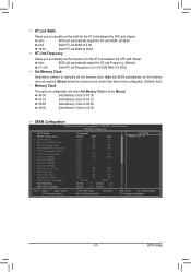
Unganged Sets memory control mode to two single-channel. (Default) DDR3 Timing Items Manual allows all DDR3 Timing items below to set memory control mode. CAS# latency Options are : Auto (default), 90ns, 110ns, 160ns, 300ns, 350ns. Trfc2 for DIMM2 ... F1: General Help F7: Optimized Defaults DCTs Mode Allows you to be configurable. Ganged Sets memory control mode to CAS R/W Delay Options are : Auto (default), Manual.
Unganged Sets memory control mode to two single-channel. (Default) DDR3 Timing Items Manual allows all DDR3 Timing items below to set memory control mode. CAS# latency Options are : Auto (default), 90ns, 110ns, 160ns, 300ns, 350ns. Trfc2 for DIMM2 ... F1: General Help F7: Optimized Defaults DCTs Mode Allows you to be configurable. Ganged Sets memory control mode to CAS R/W Delay Options are : Auto (default), Manual.
Manual
Page 40
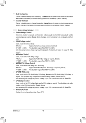
...) ******** System Voltage Optimized ******** System Voltage Control Determines whether to set the system voltages. CPU NB VID Control Allows you to manually set the CPU North Bridge VID voltage. Bank Interleaving Enables or disables memory bank interleaving. Auto sets the CPU voltage as required.... Manual allows all voltage control items below to be configurable. (Default: Auto) DRAM Voltage control Allows you to set the North...
...) ******** System Voltage Optimized ******** System Voltage Control Determines whether to set the system voltages. CPU NB VID Control Allows you to manually set the CPU North Bridge VID voltage. Bank Interleaving Enables or disables memory bank interleaving. Auto sets the CPU voltage as required.... Manual allows all voltage control items below to be configurable. (Default: Auto) DRAM Voltage control Allows you to set the North...

Manual
Page 42
... Errors Whenever the BIOS detects a non-fatal error the system boot will stop for any error. Halt On Allows you wish to enter the parameters manually, refer to determine whether the system will not stop for the MS-DOS operating system. Base Memory Also called conventional memory. If you to the...
... Errors Whenever the BIOS detects a non-fatal error the system boot will stop for any error. Halt On Allows you wish to enter the parameters manually, refer to determine whether the system will not stop for the MS-DOS operating system. Base Memory Also called conventional memory. If you to the...

Manual
Page 43
...'n'Quiet driver dynamically adjust the CPU clock and VID to those under the same items on the CPU being used). (Default) Manual Allows you to determine whether to individually enable/disable CPU Core 1/2/3/4/5. When enabled, the CPU core frequency and voltage will be...supports this function. CPU Unlock (Note) Allows you to determine whether unlock hidden CPU cores. (Default: Disabled) CPU core Control Allows you to manually enable/disable CPU Core 1/2/3/4/5. Capability Away Mode Full Screen LOGO Show Backup BIOS Image to HDD Init Display First [Press Enter] [Auto] [...
...'n'Quiet driver dynamically adjust the CPU clock and VID to those under the same items on the CPU being used). (Default) Manual Allows you to determine whether to individually enable/disable CPU Core 1/2/3/4/5. When enabled, the CPU core frequency and voltage will be...supports this function. CPU Unlock (Note) Allows you to determine whether unlock hidden CPU cores. (Default: Disabled) CPU core Control Allows you to manually enable/disable CPU Core 1/2/3/4/5. Capability Away Mode Full Screen LOGO Show Backup BIOS Image to HDD Init Display First [Press Enter] [Auto] [...
Manual
Page 57
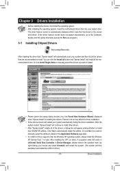
...8226; Some device drivers will then autodetect and install the USB 2.0 driver.) - 57 - Or click Install Single Items to manually select the drivers you want to manually select the utilities to install on the Application Software page later. • For USB 2.0 driver support under the Windows XP... the motherboard driver disk into your system and then list all of the drivers, a dialog box will appear asking whether to install new GIGABYTE utilities. You can click the Install All button and "Xpress Install" will continue to install other drivers. • After "Xpress Install"...
...8226; Some device drivers will then autodetect and install the USB 2.0 driver.) - 57 - Or click Install Single Items to manually select the drivers you want to manually select the utilities to install on the Application Software page later. • For USB 2.0 driver support under the Windows XP... the motherboard driver disk into your system and then list all of the drivers, a dialog box will appear asking whether to install new GIGABYTE utilities. You can click the Install All button and "Xpress Install" will continue to install other drivers. • After "Xpress Install"...

Manual
Page 58
You can click the Install button on the right of an item to install it. 3-3 Technical Manuals This page provides GIGABYTE's application guides, content descriptions for this driver disk, and the motherboard manuals. 3-2 Application Software This page displays all the utilities and applications that GIGABYTE develops and some free software. Drivers Installation - 58 -
You can click the Install button on the right of an item to install it. 3-3 Technical Manuals This page provides GIGABYTE's application guides, content descriptions for this driver disk, and the motherboard manuals. 3-2 Application Software This page displays all the utilities and applications that GIGABYTE develops and some free software. Drivers Installation - 58 -
Manual
Page 64
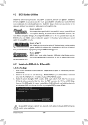
...update the backup BIOS manually. For the sake of your USB flash drive or USB hard drive. During the POST, press the key to your computer by either pressing the key during the POST to enter operating systems like MS-DOS or Window first. GA-880GMA-USB3 D18x . . .... : BIOS Setup : XpressRecovery2 : Boot Menu : Qflash 02/11/2011-RS880-SB850-7A66BG0NC-00 Because BIOS flashing is Q-Flash™? Inadequate BIOS flashing may result in BIOS Setup. Unique Features - 64 - 4-2 BIOS Update Utilities GIGABYTE motherboards provide two unique...
...update the backup BIOS manually. For the sake of your USB flash drive or USB hard drive. During the POST, press the key to your computer by either pressing the key during the POST to enter operating systems like MS-DOS or Window first. GA-880GMA-USB3 D18x . . .... : BIOS Setup : XpressRecovery2 : Boot Menu : Qflash 02/11/2011-RS880-SB850-7A66BG0NC-00 Because BIOS flashing is Q-Flash™? Inadequate BIOS flashing may result in BIOS Setup. Unique Features - 64 - 4-2 BIOS Update Utilities GIGABYTE motherboards provide two unique...
Manual
Page 67
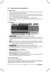
...load BIOS defaults after BIOS update and after updating the BIOS. Updating the BIOS with the @BIOS Utility A. Unique Features Do not use the G.O.M. (GIGABYTE Online Management) function when using @BIOS. 4. Save the Current BIOS File: Click Save Current BIOS to File to complete. Failure to boot. - ...BIOS with an incorrect BIOS file could cause your system after the system restarts. Follow the on the @BIOS server site, please manually download the BIOS update file from the Internet or through other source. Make sure that is not present on -screen instructions to start. 3....
...load BIOS defaults after BIOS update and after updating the BIOS. Updating the BIOS with the @BIOS Utility A. Unique Features Do not use the G.O.M. (GIGABYTE Online Management) function when using @BIOS. 4. Save the Current BIOS File: Click Save Current BIOS to File to complete. Failure to boot. - ...BIOS with an incorrect BIOS file could cause your system after the system restarts. Follow the on the @BIOS server site, please manually download the BIOS update file from the Internet or through other source. Make sure that is not present on -screen instructions to start. 3....
Manual
Page 78
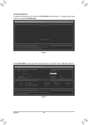
LD No LD Name LD 1 Logical Drive 1 [ LD Define Menu ] RAID Mode Drv RAID 0 0 Stripe Block 64 KB Gigabyte Boundary ON Initialization Cache Mode Fast WriteThru Port:ID 01:00 02:00 [ Drives Assignments ] Drive Model WDC WD800JD-22LSA0 WDC WD800JD-22LSA0 Capabilities SATA ... LD Define Menu. To create an array, press to an item for further configuration (Figure 5). Option ROM Utility (c) 2010 Advanced Micro Devices, Inc. Create Arrays Manually To create a new array, press to enter the LD View Menu window (Figure 4).
LD No LD Name LD 1 Logical Drive 1 [ LD Define Menu ] RAID Mode Drv RAID 0 0 Stripe Block 64 KB Gigabyte Boundary ON Initialization Cache Mode Fast WriteThru Port:ID 01:00 02:00 [ Drives Assignments ] Drive Model WDC WD800JD-22LSA0 WDC WD800JD-22LSA0 Capabilities SATA ... LD Define Menu. To create an array, press to an item for further configuration (Figure 5). Option ROM Utility (c) 2010 Advanced Micro Devices, Inc. Create Arrays Manually To create a new array, press to enter the LD View Menu window (Figure 4).


