
Manual
Page 3
Changes to the specifications and features in this manual may be made by GIGABYTE without GIGABYTE's prior written permission. Example: Check your motherboard looks like this product, GIGABYTE provides the following types of documentations: For quick set-up of the motherboard ...is 1.0. For product-related information, check on our website at: http://www.gigabyte.com Identifying Your Motherboard Revision The revision number on your motherboard revision before updating motherboard BIOS, drivers, or when looking for technical information. For example, "REV: 1.0" means...
Changes to the specifications and features in this manual may be made by GIGABYTE without GIGABYTE's prior written permission. Example: Check your motherboard looks like this product, GIGABYTE provides the following types of documentations: For quick set-up of the motherboard ...is 1.0. For product-related information, check on our website at: http://www.gigabyte.com Identifying Your Motherboard Revision The revision number on your motherboard revision before updating motherboard BIOS, drivers, or when looking for technical information. For example, "REV: 1.0" means...
Manual
Page 4
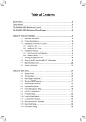
Table of Contents Box Contents...6 Optional Items...6 GA-880GMA-USB3 Motherboard Layout 7 GA-880GMA-USB3 Motherboard Block Diagram 8 Chapter 1 Hardware Installation 9 1-1 Installation Precautions 9 1-2 Product Specifications 10 1-3 Installing the CPU and CPU Cooler...8482; Configuration 19 1-7 Back Panel Connectors 20 1-8 Internal Connectors 23 Chapter 2 BIOS Setup 31 2-1 Startup Screen 32 2-2 The Main Menu 33 2-3 MB Intelligent Tweaker(M.I.T 35 2-4 Standard CMOS Features 41 2-5 Advanced BIOS Features 43 2-6 Integrated Peripherals 45 2-7 Power Management Setup 49 2-8 PnP/PCI ...
Table of Contents Box Contents...6 Optional Items...6 GA-880GMA-USB3 Motherboard Layout 7 GA-880GMA-USB3 Motherboard Block Diagram 8 Chapter 1 Hardware Installation 9 1-1 Installation Precautions 9 1-2 Product Specifications 10 1-3 Installing the CPU and CPU Cooler...8482; Configuration 19 1-7 Back Panel Connectors 20 1-8 Internal Connectors 23 Chapter 2 BIOS Setup 31 2-1 Startup Screen 32 2-2 The Main Menu 33 2-3 MB Intelligent Tweaker(M.I.T 35 2-4 Standard CMOS Features 41 2-5 Advanced BIOS Features 43 2-6 Integrated Peripherals 45 2-7 Power Management Setup 49 2-8 PnP/PCI ...
Manual
Page 5
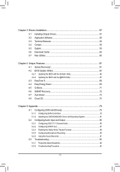
... 58 3-4 Contact...59 3-5 System...59 3-6 Download Center 60 3-7 New Utilities...60 Chapter 4 Unique Features 61 4-1 Xpress Recovery2 61 4-2 BIOS Update Utilities 64 4-2-1 Updating the BIOS with the Q-Flash Utility 64 4-2-2 Updating the BIOS with the @BIOS Utility 67 4-3 EasyTune 6...68 4-4 Easy Energy Saver 69 4-5 Q-Share...71 4-6 SMART Recovery 72 4-7 Auto Green...73 4-8 Cloud OC...
... 58 3-4 Contact...59 3-5 System...59 3-6 Download Center 60 3-7 New Utilities...60 Chapter 4 Unique Features 61 4-1 Xpress Recovery2 61 4-2 BIOS Update Utilities 64 4-2-1 Updating the BIOS with the Q-Flash Utility 64 4-2-2 Updating the BIOS with the @BIOS Utility 67 4-3 EasyTune 6...68 4-4 Easy Energy Saver 69 4-5 Q-Share...71 4-6 SMART Recovery 72 4-7 Auto Green...73 4-8 Cloud OC...
Manual
Page 8
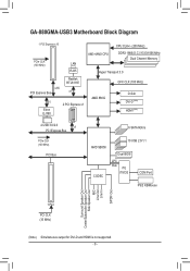
GA-880GMA-USB3 Motherboard Block Diagram 1 PCI Express x16 CPU CLK+/- (200 MHz) PCIe CLK (100 MHz) AM3+/AM3 CPU DDR3 1866(O.C.)/1333/1066 MHz Dual Channel Memory ... MHz) D-Sub DVI-D (Note) HDMI (Note) 2 USB 3.0/2.0 x1 PCI Express Bus PCIe CLK (100 MHz) PCI Bus 6 SATA 6Gb/s AMD SB850 CODEC 10 USB 2.0/1.1 Dual BIOS LPC Bus iTE IT8720 COM Port PS/2 KB/Mouse Surround Speaker Out Center/Subwoofer Speaker Out Side Speaker Out MIC Line Out Line In S/PDIF...
GA-880GMA-USB3 Motherboard Block Diagram 1 PCI Express x16 CPU CLK+/- (200 MHz) PCIe CLK (100 MHz) AM3+/AM3 CPU DDR3 1866(O.C.)/1333/1066 MHz Dual Channel Memory ... MHz) D-Sub DVI-D (Note) HDMI (Note) 2 USB 3.0/2.0 x1 PCI Express Bus PCIe CLK (100 MHz) PCI Bus 6 SATA 6Gb/s AMD SB850 CODEC 10 USB 2.0/1.1 Dual BIOS LPC Bus iTE IT8720 COM Port PS/2 KB/Mouse Surround Speaker Out Center/Subwoofer Speaker Out Side Speaker Out MIC Line Out Line In S/PDIF...
Manual
Page 11
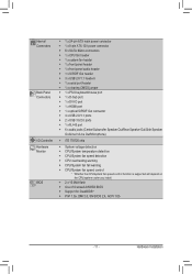
Internal Connectors Back Panel Connectors I/O Controller Hardware Monitor BIOS ŠŠ 1 x 24-pin ATX main power connector ŠŠ 1 x 8-pin ATX 12V power connector ŠŠ 6 x SATA 6Gb/s connectors ŠŠ 1 x CPU fan header &#... speed control function is supported will depend on the CPU/system cooler you install. ŠŠ 2 x 16 Mbit flash ŠŠ Use of licensed AWARD BIOS ŠŠ Support for DualBIOS™ ŠŠ PnP 1.0a, DMI 2.0, SM...
Internal Connectors Back Panel Connectors I/O Controller Hardware Monitor BIOS ŠŠ 1 x 24-pin ATX main power connector ŠŠ 1 x 8-pin ATX 12V power connector ŠŠ 6 x SATA 6Gb/s connectors ŠŠ 1 x CPU fan header &#... speed control function is supported will depend on the CPU/system cooler you install. ŠŠ 2 x 16 Mbit flash ŠŠ Use of licensed AWARD BIOS ŠŠ Support for DualBIOS™ ŠŠ PnP 1.0a, DMI 2.0, SM...
Manual
Page 12
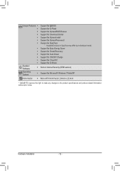
Hardware Installation - 12 - Unique Features ŠŠ Support for @BIOS ŠŠ Support for Q-Flash ŠŠ Support for Xpress BIOS Rescue ŠŠ Support for Download Center ŠŠ Support for Xpress Install ŠŠ Support for Xpress Recovery2 ŠŠ Support for EasyTune...) Operating System ŠŠ Support for Microsoft® Windows 7/Vista/XP Form Factor ŠŠ Micro ATX Form Factor; 24.4cm x 23.4cm * GIGABYTE reserves the right to make any changes to the product specifications and product-related information without prior notice.
Hardware Installation - 12 - Unique Features ŠŠ Support for @BIOS ŠŠ Support for Q-Flash ŠŠ Support for Xpress BIOS Rescue ŠŠ Support for Download Center ŠŠ Support for Xpress Install ŠŠ Support for Xpress Recovery2 ŠŠ Support for EasyTune...) Operating System ŠŠ Support for Microsoft® Windows 7/Vista/XP Form Factor ŠŠ Micro ATX Form Factor; 24.4cm x 23.4cm * GIGABYTE reserves the right to make any changes to the product specifications and product-related information without prior notice.
Manual
Page 16
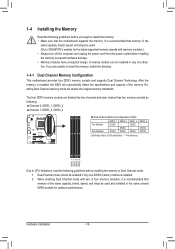
... be installed in only one DDR3 memory module is recommended that memory of the memory. Hardware Installation - 16 - A memory module can be used . (Go to GIGABYTE's website for optimum performance. DS/SS DDR3_4 - It is installed, the BIOS will double the original memory bandwidth.
... be installed in only one DDR3 memory module is recommended that memory of the memory. Hardware Installation - 16 - A memory module can be used . (Go to GIGABYTE's website for optimum performance. DS/SS DDR3_4 - It is installed, the BIOS will double the original memory bandwidth.
Manual
Page 18
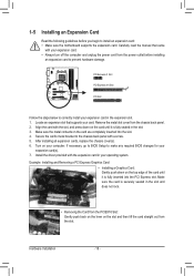
... that came with the expansion card in the slot. 3. Remove the metal slot cover from the power outlet before you begin to make any required BIOS changes for your computer. Example: Installing and Removing a PCI Express Graphics Card: • Installing a Graphics Card: Gently push down on the card until it is.... Turn on the card are completely inserted into the PCI Express slot. Make sure the metal contacts on your expansion card(s). 7. If necessary, go to BIOS Setup to install an expansion card: • Make sure the motherboard supports the expansion card.
... that came with the expansion card in the slot. 3. Remove the metal slot cover from the power outlet before you begin to make any required BIOS changes for your computer. Example: Installing and Removing a PCI Express Graphics Card: • Installing a Graphics Card: Gently push down on the card until it is.... Turn on the card are completely inserted into the PCI Express slot. Make sure the metal contacts on your expansion card(s). 7. If necessary, go to BIOS Setup to install an expansion card: • Make sure the motherboard supports the expansion card.

Manual
Page 19
... Display First to set the following instructions on the back panel. An ATI Hybrid CrossFireX-supported graphics card (Note 1) B. BIOS Setup Enter BIOS Setup to OnChipVGA. An ATI Hybrid CrossFireX-supported motherboard and correct driver - Select CrossFire™ on the Graphics menu on the...Plug the display cable into the onboard graphics port on configuring an ATI Hybrid CrossFireX system. Read the following items under the Advanced BIOS Features menu: - C. Set Internal Graphics Mode to 256MB or 512MB. (Note 2) - Configuring the Graphics Driver After installing ...
... Display First to set the following instructions on the back panel. An ATI Hybrid CrossFireX-supported graphics card (Note 1) B. BIOS Setup Enter BIOS Setup to OnChipVGA. An ATI Hybrid CrossFireX-supported motherboard and correct driver - Select CrossFire™ on the Graphics menu on the...Plug the display cable into the onboard graphics port on configuring an ATI Hybrid CrossFireX system. Read the following items under the Advanced BIOS Features menu: - C. Set Internal Graphics Mode to 256MB or 512MB. (Note 2) - Configuring the Graphics Driver After installing ...
Manual
Page 21
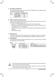
...No data transmission or receiving is compatible to the recommended system requirements (or better) below shows the supported dual display configurations. vanced BIOS Features," for more information) • Playback software: CyberLink PowerDVD 8.0 or later (Note: Please ensure Hardware Acceleration is enabled.) ... Port The USB 3.0 port supports the USB 3.0 specification and is occurring • When removing the cable connected to Chapter 2, "BIOS Setup," "Ad- The following describes the states of UMA Frame Buffer Size (refer to a back panel connector, first remove the cable...
...No data transmission or receiving is compatible to the recommended system requirements (or better) below shows the supported dual display configurations. vanced BIOS Features," for more information) • Playback software: CyberLink PowerDVD 8.0 or later (Note: Please ensure Hardware Acceleration is enabled.) ... Port The USB 3.0 port supports the USB 3.0 specification and is occurring • When removing the cable connected to Chapter 2, "BIOS Setup," "Ad- The following describes the states of UMA Frame Buffer Size (refer to a back panel connector, first remove the cable...
Manual
Page 26
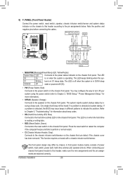
...MSG+ MSG- This function requires a chassis with a chassis intrusion switch/sensor. When connecting your system using the power switch (refer to Chapter 2, "BIOS Setup," "Power Management Setup," for information about beep codes. • HD (Hard Drive Activity LED, Blue) Connects to the chassis intrusion switch/...RESRES+ CICI+ PWR+ PWR- The system reports system startup status by chassis. The LED S0 On is on when the system is detected, the BIOS may configure the way to turn off (S5). • PW (Power Switch, Red): Connects to the power status indicator on the chassis front...
...MSG+ MSG- This function requires a chassis with a chassis intrusion switch/sensor. When connecting your system using the power switch (refer to Chapter 2, "BIOS Setup," "Power Management Setup," for information about beep codes. • HD (Hard Drive Activity LED, Blue) Connects to the chassis intrusion switch/...RESRES+ CICI+ PWR+ PWR- The system reports system startup status by chassis. The LED S0 On is on when the system is detected, the BIOS may configure the way to turn off (S5). • PW (Power Switch, Red): Connects to the power status indicator on the chassis front...
Manual
Page 29
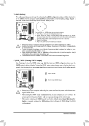
...may be accurate or may cause damage to the motherboard. • After system restart, go to BIOS Setup to load factory defaults (select Load Optimized Defaults) or manually configure the BIOS settings (refer to clear the CMOS values (e.g. Open: Normal Short: Clear CMOS Values • ... and the negative side (-) of the battery holder, making them short for BIOS configurations). - 29 - Replace the battery. 4. date information and BIOS configurations) and reset the CMOS values to keep the values (such as BIOS configurations, date, and time information) in the CMOS when the computer is...
...may be accurate or may cause damage to the motherboard. • After system restart, go to BIOS Setup to load factory defaults (select Load Optimized Defaults) or manually configure the BIOS settings (refer to clear the CMOS values (e.g. Open: Normal Short: Clear CMOS Values • ... and the negative side (-) of the battery holder, making them short for BIOS configurations). - 29 - Replace the battery. 4. date information and BIOS configurations) and reset the CMOS values to keep the values (such as BIOS configurations, date, and time information) in the CMOS when the computer is...
Manual
Page 31
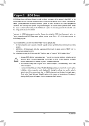
... user to modify basic system configuration settings or to boot. To upgrade the BIOS, use either the GIGABYTE Q-Flash or @BIOS utility. • Q-Flash allows the user to quickly and easily upgrade or back up BIOS without entering the operating system. • @BIOS is a Windows-based utility that you can press + in Chapter 1 for the...
... user to modify basic system configuration settings or to boot. To upgrade the BIOS, use either the GIGABYTE Q-Flash or @BIOS utility. • Q-Flash allows the user to quickly and easily upgrade or back up BIOS without entering the operating system. • @BIOS is a Windows-based utility that you can press + in Chapter 1 for the...
Manual
Page 32
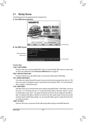
...configured in Boot Menu. BIOS Setup - 32 - Motherboard Model BIOS Version GA-880GMA-USB3 D18x . . . . : BIOS Setup : XpressRecovery2 : Boot Menu : Qflash 02/11/2011-RS880-SB850-7A66BG0NC-00 Function Keys Function Keys Function Keys: : POST SCREEN Press the key to show the BIOS POST screen at system ... access Boot Menu again to change the first boot device setting as needed. : Q-FLASH Press the key to enter BIOS Setup first. The POST Screen Award Modular BIOS v6.00PG Copyright (C) 1984-2011, Award Software, Inc. The LOGO Screen (Default) B. For more information, refer to...
...configured in Boot Menu. BIOS Setup - 32 - Motherboard Model BIOS Version GA-880GMA-USB3 D18x . . . . : BIOS Setup : XpressRecovery2 : Boot Menu : Qflash 02/11/2011-RS880-SB850-7A66BG0NC-00 Function Keys Function Keys Function Keys: : POST SCREEN Press the key to show the BIOS POST screen at system ... access Boot Menu again to change the first boot device setting as needed. : Q-FLASH Press the key to enter BIOS Setup first. The POST Screen Award Modular BIOS v6.00PG Copyright (C) 1984-2011, Award Software, Inc. The LOGO Screen (Default) B. For more information, refer to...
Manual
Page 33
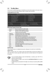
...Item F10: Save & Exit Setup Change CPU's Clock & Voltage F11: Save CMOS to BIOS F12: Load CMOS from BIOS Main Menu Help The on-screen description of a highlighted setup option is in the Item Help...right side of the submenu. • If you do not find the settings you enter the BIOS Setup program, the Main Menu (as usual, select the Load Optimized Defaults item to set ... the current submenus Access the Q-Flash utility Display system information Save all the changes and exit the BIOS Setup program Save CMOS to display a help screen. Submenu Help While in the Main Menu or ...
...Item F10: Save & Exit Setup Change CPU's Clock & Voltage F11: Save CMOS to BIOS F12: Load CMOS from BIOS Main Menu Help The on-screen description of a highlighted setup option is in the Item Help...right side of the submenu. • If you do not find the settings you enter the BIOS Setup program, the Main Menu (as usual, select the Load Optimized Defaults item to set ... the current submenus Access the Q-Flash utility Display system information Save all the changes and exit the BIOS Setup program Save CMOS to display a help screen. Submenu Help While in the Main Menu or ...
Manual
Page 34
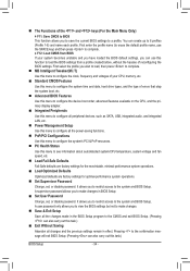
... then press to complete. MB Intelligent Tweaker(M.I.T.) Use this task.) Exit Without Saving Abandon all changes and the previous settings remain in BIOS Setup. Set User Password Change, set , or disable password. A supervisor password allows you to make changes. Save & Exit Setup...configure the system time and date, hard drive types, and the type of errors that stop the system boot, etc. Advanced BIOS Features Use this menu to configure the device boot order, advanced features available on the CPU, and the primary display adapter. ...
... then press to complete. MB Intelligent Tweaker(M.I.T.) Use this task.) Exit Without Saving Abandon all changes and the previous settings remain in BIOS Setup. Set User Password Change, set , or disable password. A supervisor password allows you to make changes. Save & Exit Setup...configure the system time and date, hard drive types, and the type of errors that stop the system boot, etc. Advanced BIOS Features Use this menu to configure the device boot order, advanced features available on the CPU, and the primary display adapter. ...
Manual
Page 35
... other unexpected results. (Inadequately altering the settings may result in system's failure to CPU, chipset, or memory and reduce the useful life of these components. BIOS Setup
... other unexpected results. (Inadequately altering the settings may result in system's failure to CPU, chipset, or memory and reduce the useful life of these components. BIOS Setup
Manual
Page 36
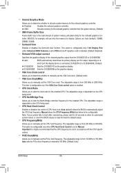
... Size Frame buffer size is dependent on the CPU being used . Important It is set in accordance with the CPU specifications. Auto BIOS automatically determines the primary display port for output, depending on the CPU being used . CPU Host Clock Control Enables or disables the control... to PEG and an ATI graphics card is set the CPU host frequency. This option is configurable only if Init Display First under Advanced BIOS Features is installed. (Default: Disabled) Onboard VGA output connect Specifies the graphics display of CPU host clock. The adjustable range is connected,...
... Size Frame buffer size is dependent on the CPU being used . Important It is set in accordance with the CPU specifications. Auto BIOS automatically determines the primary display port for output, depending on the CPU being used . CPU Host Clock Control Enables or disables the control... to PEG and an ATI graphics card is set the CPU host frequency. This option is configurable only if Init Display First under Advanced BIOS Features is installed. (Default: Disabled) Onboard VGA output connect Specifies the graphics display of CPU host clock. The adjustable range is connected,...
Manual
Page 37
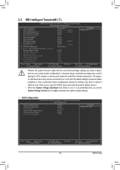
... Clock to X4.00. Auto 5T 5T Auto 110ns 110ns Auto -- -- Auto -- -- HT Link Width Allows you to X5.33. Auto BIOS will automatically adjust the HT Link Frequency. (Default) x1~x10 Sets HT Link Frequency to RAS Delay **DCTs Drive Strength** ProcOdt(ohms) DQS Drive... -- -- Manual allows the memory clock control item below to manually set the frequency for the HT Link between the CPU and chipset. BIOS Setup Set Memory Clock Determines whether to be configurable. (Default: Auto) Memory Clock This option is configurable only when Set Memory Clock is...
... Clock to X4.00. Auto 5T 5T Auto 110ns 110ns Auto -- -- Auto -- -- HT Link Width Allows you to X5.33. Auto BIOS will automatically adjust the HT Link Frequency. (Default) x1~x10 Sets HT Link Frequency to RAS Delay **DCTs Drive Strength** ProcOdt(ohms) DQS Drive... -- -- Manual allows the memory clock control item below to manually set the frequency for the HT Link between the CPU and chipset. BIOS Setup Set Memory Clock Determines whether to be configurable. (Default: Auto) Memory Clock This option is configurable only when Set Memory Clock is...

Manual
Page 38
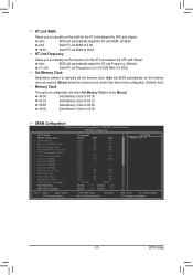
RAS to single dual-channel. BIOS Setup - 38 - CMOS Setup Utility-Copyright (C) 1984-2011 Award Software DRAM Configuration Data Drive Strength MEMCLK Drive Strength Addr/Cmd Drive Strength CS/ODT Drive ...
RAS to single dual-channel. BIOS Setup - 38 - CMOS Setup Utility-Copyright (C) 1984-2011 Award Software DRAM Configuration Data Drive Strength MEMCLK Drive Strength Addr/Cmd Drive Strength CS/ODT Drive ...


