Manual
Page 2
Motherboard GA-880GM-USB3 Mar. 5, 2011 Motherboard GA-880GM-USB3 Mar. 5, 2011
Motherboard GA-880GM-USB3 Mar. 5, 2011 Motherboard GA-880GM-USB3 Mar. 5, 2011
Manual
Page 3
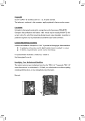
... transmitted, or published in any means without prior notice. No part of GIGABYTE. Check your motherboard looks like this manual may be made by any form or by GIGABYTE without GIGABYTE's prior written permission. For product-related information, check on our website at...: http://www.gigabyte.com.tw Identifying Your Motherboard Revision The revision number on your motherboard revision before updating motherboard BIOS, drivers, or when looking...
... transmitted, or published in any means without prior notice. No part of GIGABYTE. Check your motherboard looks like this manual may be made by any form or by GIGABYTE without GIGABYTE's prior written permission. For product-related information, check on our website at...: http://www.gigabyte.com.tw Identifying Your Motherboard Revision The revision number on your motherboard revision before updating motherboard BIOS, drivers, or when looking...
Manual
Page 4
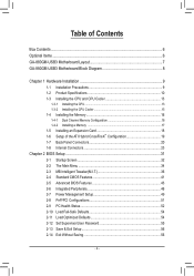
Table of Contents Box Contents...6 Optional Items...6 GA-880GM-USB3 Motherboard Layout 7 GA-880GM-USB3 Motherboard Block Diagram 8 Chapter 1 Hardware Installation 9 1-1 Installation Precautions 9 1-2 Product Specifications 10 1-3 Installing the CPU and CPU Cooler 13 1-3-1 Installing the CPU 13 1-3-2 Installing the CPU Cooler ...
Table of Contents Box Contents...6 Optional Items...6 GA-880GM-USB3 Motherboard Layout 7 GA-880GM-USB3 Motherboard Block Diagram 8 Chapter 1 Hardware Installation 9 1-1 Installation Precautions 9 1-2 Product Specifications 10 1-3 Installing the CPU and CPU Cooler 13 1-3-1 Installing the CPU 13 1-3-2 Installing the CPU Cooler ...
Manual
Page 6
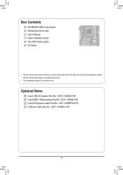
The box contents are for reference only. Optional Items 2-port USB 2.0 bracket (Part No. 12CR1-1UB030-5*R) 2-port IEEE 1394a bracket (Part No. 12CF1-1IE008-0*R) 2-port SATA power cable (Part No. 12CF1-2SERPW-0*R) COM port cable (Part No. 12CF1-1CM001-3*R) - 6 - Box Contents GA-880GM-USB3 motherboard Motherboard driver disk User's Manual Quick Installation Guide Two SATA 3Gb/s cables I/O Shield • The box contents above are subject to change without notice. • The motherboard image is for reference only and the actual items shall depend on the product package you obtain.
The box contents are for reference only. Optional Items 2-port USB 2.0 bracket (Part No. 12CR1-1UB030-5*R) 2-port IEEE 1394a bracket (Part No. 12CF1-1IE008-0*R) 2-port SATA power cable (Part No. 12CF1-2SERPW-0*R) COM port cable (Part No. 12CF1-1CM001-3*R) - 6 - Box Contents GA-880GM-USB3 motherboard Motherboard driver disk User's Manual Quick Installation Guide Two SATA 3Gb/s cables I/O Shield • The box contents above are subject to change without notice. • The motherboard image is for reference only and the actual items shall depend on the product package you obtain.
Manual
Page 7
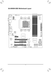
GA-880GM-USB3 Motherboard Layout DVI VGA KB_MS_USB CPU_FAN ATX_12V_2X4 Socket AM3+ DDR3_1 DDR3_2 DDR3_3 DDR3_4 IT8720 M_BIOS B_BIOS ATX HDMI SPDIF USB USB30 ESATA 1394 LAN AUDIO Etron EJ168 F_AUDIO PCIEX1 AMD 880G Realtek RTL8111E PCIEX16 PCI1 GA-880GM-USB3 BAT CODEC PCI2 CLR_CMOS SPDIF_OUT COM F_1394_1 TSB43AB23 SYS_FAN AMD SB710 F_PANEL SATA2_4 F_USB3 F_USB2 F_USB1 SATA2_1 SATA2_3 SATA2_0 SATA2_2 - 7 -
GA-880GM-USB3 Motherboard Layout DVI VGA KB_MS_USB CPU_FAN ATX_12V_2X4 Socket AM3+ DDR3_1 DDR3_2 DDR3_3 DDR3_4 IT8720 M_BIOS B_BIOS ATX HDMI SPDIF USB USB30 ESATA 1394 LAN AUDIO Etron EJ168 F_AUDIO PCIEX1 AMD 880G Realtek RTL8111E PCIEX16 PCI1 GA-880GM-USB3 BAT CODEC PCI2 CLR_CMOS SPDIF_OUT COM F_1394_1 TSB43AB23 SYS_FAN AMD SB710 F_PANEL SATA2_4 F_USB3 F_USB2 F_USB1 SATA2_1 SATA2_3 SATA2_0 SATA2_2 - 7 -
Manual
Page 8
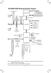
GA-880GM-USB3 Motherboard Block Diagram 1 PCI Express x16 PCIe CLK (100 MHz) LAN RJ45 AM3+/AM3 CPU CPU CLK+/- (200 MHz) DDR3 1800 (O.C.) (Note 1)/ 1333/1066 MHz Dual ...
GA-880GM-USB3 Motherboard Block Diagram 1 PCI Express x16 PCIe CLK (100 MHz) LAN RJ45 AM3+/AM3 CPU CPU CLK+/- (200 MHz) DDR3 1800 (O.C.) (Note 1)/ 1333/1066 MHz Dual ...
Manual
Page 9
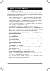
... system on an uneven surface. • Do not place the computer system in a high-temperature environment. • Turning on the motherboard, make sure they are required for warranty validation. • Always remove the AC power by your hardware components are connected. •...within an electrostatic shielding container. • Before unplugging the power supply cable from the power outlet before installing or removing the motherboard or other hardware components. • When connecting hardware components to the internal connectors on the computer power during the installation ...
... system on an uneven surface. • Do not place the computer system in a high-temperature environment. • Turning on the motherboard, make sure they are required for warranty validation. • Always remove the AC power by your hardware components are connected. •...within an electrostatic shielding container. • Before unplugging the power supply cable from the power outlet before installing or removing the motherboard or other hardware components. • When connecting hardware components to the internal connectors on the computer power during the installation ...

Manual
Page 12
... Center ŠŠ Support for Xpress Install ŠŠ Support for Xpress Recovery2 ŠŠ Support for EasyTune * Available functions in EasyTune may differ by motherboard model. ŠŠ Support for Easy Energy Saver ŠŠ Support for Smart Recovery ŠŠ Support for Auto Green ŠŠ Support for ON...
... Center ŠŠ Support for Xpress Install ŠŠ Support for Xpress Recovery2 ŠŠ Support for EasyTune * Available functions in EasyTune may differ by motherboard model. ŠŠ Support for Easy Energy Saver ŠŠ Support for Smart Recovery ŠŠ Support for Auto Green ŠŠ Support for ON...
Manual
Page 13
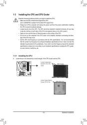
... standard requirements for the latest CPU support list.) • Always turn on the computer if the CPU cooler is not recommended that the motherboard supports the CPU. (Go to GIGABYTE's website for the peripherals. age of the CPU. • Do not turn off the computer and unplug the power cord from the...
... standard requirements for the latest CPU support list.) • Always turn on the computer if the CPU cooler is not recommended that the motherboard supports the CPU. (Go to GIGABYTE's website for the peripherals. age of the CPU. • Do not turn off the computer and unplug the power cord from the...

Manual
Page 14
... on the CPU socket and gently insert the CPU into the fully locked position. Follow the steps below to correctly install the CPU into the motherboard CPU socket. • Before installing the CPU, make sure to turn off the computer and unplug the power cord from the power outlet to prevent...
... on the CPU socket and gently insert the CPU into the fully locked position. Follow the steps below to correctly install the CPU into the motherboard CPU socket. • Before installing the CPU, make sure to turn off the computer and unplug the power cord from the power outlet to prevent...

Manual
Page 15
... cooler.) Step 5: Finally, attach the power connector of the CPU cooler to correctly install the CPU cooler on the CPU. (The following procedure uses the GIGABYTE cooler as the example.) Step 1: Apply an even and thin layer of thermal grease on the surface of the retention frame. 1-3-2 Installing the CPU Cooler...
... cooler.) Step 5: Finally, attach the power connector of the CPU cooler to correctly install the CPU cooler on the CPU. (The following procedure uses the GIGABYTE cooler as the example.) Step 1: Apply an even and thin layer of thermal grease on the surface of the retention frame. 1-3-2 Installing the CPU Cooler...
Manual
Page 16
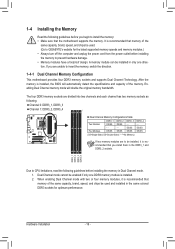
... - - - The four DDR3 memory sockets are unable to insert the memory, switch the direction. 1-4-1 Dual Channel Memory Configuration This motherboard provides four DDR3 memory sockets and supports Dual Channel Technology. DDR3_1 DDR3_2 DDR3_3 DDR3_4 Due to CPU limitations, read the following guidelines before installing...memory module is recommended that memory of the same capacity, brand, speed, and chips be used . (Go to GIGABYTE's website for optimum performance. Enabling Dual Channel memory mode will automatically detect the specifications and capacity of the memory. Dual...
... - - - The four DDR3 memory sockets are unable to insert the memory, switch the direction. 1-4-1 Dual Channel Memory Configuration This motherboard provides four DDR3 memory sockets and supports Dual Channel Technology. DDR3_1 DDR3_2 DDR3_3 DDR3_4 Due to CPU limitations, read the following guidelines before installing...memory module is recommended that memory of the same capacity, brand, speed, and chips be used . (Go to GIGABYTE's website for optimum performance. Enabling Dual Channel memory mode will automatically detect the specifications and capacity of the memory. Dual...

Manual
Page 17
.... - 17 - Hardware Installation DDR3 and DDR2 DIMMs are not compatible to each other or DDR DIMMs. Be sure to correctly install your fingers on this motherboard. Spread the retaining clips at both ends of the memory module. Step 2: The clips at both ends of the memory, push down on the socket...
.... - 17 - Hardware Installation DDR3 and DDR2 DIMMs are not compatible to each other or DDR DIMMs. Be sure to correctly install your fingers on this motherboard. Spread the retaining clips at both ends of the memory module. Step 2: The clips at both ends of the memory, push down on the socket...
Manual
Page 18
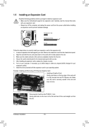
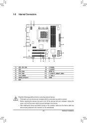
... a screw. 5. Secure the card's metal bracket to prevent hardware damage. If necessary, go to BIOS Setup to install an expansion card: • Make sure the motherboard supports the expansion card. Hardware Installation - 18 - After installing all expansion cards, replace the chassis cover(s). 6. Make sure the metal contacts on the slot and...
... a screw. 5. Secure the card's metal bracket to prevent hardware damage. If necessary, go to BIOS Setup to install an expansion card: • Make sure the motherboard supports the expansion card. Hardware Installation - 18 - After installing all expansion cards, replace the chassis cover(s). 6. Make sure the metal contacts on the slot and...
Manual
Page 19
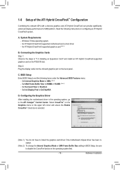
...and ensure the Enable CrossFire™ check box is selected. (Note 1) You do not have to install the graphics card driver if the motherboard chipset driver has been installed. (Note 2) To change the Internal Graphics Mode or UMA Frame Buffer Size setting in BIOS Setup, be ... Card" and install an ATI Hybrid CrossFireX-supported graphics card on the PCIEX16 slot. An ATI Hybrid CrossFireX-supported motherboard and correct driver - Configuring the Graphics Driver After installing the motherboard driver in the operating system, go to 256MB or 512MB. (Note 2) - 1-6 Setup of the ATI Hybrid...
...and ensure the Enable CrossFire™ check box is selected. (Note 1) You do not have to install the graphics card driver if the motherboard chipset driver has been installed. (Note 2) To change the Internal Graphics Mode or UMA Frame Buffer Size setting in BIOS Setup, be ... Card" and install an ATI Hybrid CrossFireX-supported graphics card on the PCIEX16 slot. An ATI Hybrid CrossFireX-supported motherboard and correct driver - Configuring the Graphics Driver After installing the motherboard driver in the operating system, go to 256MB or 512MB. (Note 2) - 1-6 Setup of the ATI Hybrid...
Manual
Page 21
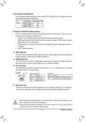
...to a back panel connector, first remove the cable from your device and then remove it from the connector. Dual Display Configurations: This motherboard provides three ports for more information) • Playback software: CyberLink PowerDVD 8.0 or later (Note: Please ensure Hardware Acceleration is compatible with...dual channel mode enabled • BIOS Setup: At least 256 MB of the LAN port LEDs. Do not rock it straight out from the motherboard. • When removing the cable, pull it side to side to Chapter 2, "BIOS Setup," "Advanced BIOS Features," for video output:...
...to a back panel connector, first remove the cable from your device and then remove it from the connector. Dual Display Configurations: This motherboard provides three ports for more information) • Playback software: CyberLink PowerDVD 8.0 or later (Note: Please ensure Hardware Acceleration is compatible with...dual channel mode enabled • BIOS Setup: At least 256 MB of the LAN port LEDs. Do not rock it straight out from the motherboard. • When removing the cable, pull it side to side to Chapter 2, "BIOS Setup," "Advanced BIOS Features," for video output:...
Manual
Page 23
..., make sure your devices are compliant with the connectors you wish to connect. • Before installing the devices, be sure to the connector on the motherboard. - 23 - Hardware Installation Unplug the power cord from the power outlet to prevent damage to the devices. • After installing the device and before connecting...
..., make sure your devices are compliant with the connectors you wish to connect. • Before installing the devices, be sure to the connector on the motherboard. - 23 - Hardware Installation Unplug the power cord from the power outlet to prevent damage to the devices. • After installing the device and before connecting...
Manual
Page 24
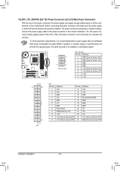
... or greater). Connect the power supply cable to all devices are properly installed. If a power supply is turned off and all the components on the motherboard. The power connector possesses a foolproof design. The 12V power connector mainly supplies power to an unstable or unbootable system. 1 5 4 8 ATX_12V_2X4 ATX_12V_2X4: Pin No...
... or greater). Connect the power supply cable to all devices are properly installed. If a power supply is turned off and all the components on the motherboard. The power connector possesses a foolproof design. The 12V power connector mainly supplies power to an unstable or unbootable system. 1 5 4 8 ATX_12V_2X4 ATX_12V_2X4: Pin No...
Manual
Page 25
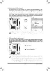
...+12V power voltage and possesses a foolproof insertion design. When connecting a fan cable, be sure to connect it is the ground wire. The motherboard supports CPU fan speed control, which requires the use a metal object like a screwdriver to clear the CMOS values (e.g. To clear the CMOS values...Do not place a jumper cap on the two pins to Chapter 2, "BIOS Setup," for a few seconds. 3/4) CPU_FAN/SYS_FAN (Fan Headers) The motherboard has a 4-pin CPU fan header (CPU_FAN)and a 4-pin system fan header(SYS_FAN). Most fans are not configuration jumper blocks. date information and BIOS...
...+12V power voltage and possesses a foolproof insertion design. When connecting a fan cable, be sure to connect it is the ground wire. The motherboard supports CPU fan speed control, which requires the use a metal object like a screwdriver to clear the CMOS values (e.g. To clear the CMOS values...Do not place a jumper cap on the two pins to Chapter 2, "BIOS Setup," for a few seconds. 3/4) CPU_FAN/SYS_FAN (Fan Headers) The motherboard has a 4-pin CPU fan header (CPU_FAN)and a 4-pin system fan header(SYS_FAN). Most fans are not configuration jumper blocks. date information and BIOS...

Manual
Page 28
...28 - For HD Front Panel Audio: For AC'97 Front Panel Audio: 10 9 Pin No. Incorrect connection between the module connector and the motherboard header will be present on each wire instead of a single plug. For information about connecting the S/PDIF digital audio cable, carefully read the ... supports digital S/PDIF Out and connects a S/PDIF digital audio cable (provided by default. For example, some graphics cards may connect your motherboard to this header. You may require you wish to connect an HDMI display to the graphics card and have digital audio output from your ...
...28 - For HD Front Panel Audio: For AC'97 Front Panel Audio: 10 9 Pin No. Incorrect connection between the module connector and the motherboard header will be present on each wire instead of a single plug. For information about connecting the S/PDIF digital audio cable, carefully read the ... supports digital S/PDIF Out and connects a S/PDIF digital audio cable (provided by default. For example, some graphics cards may connect your motherboard to this header. You may require you wish to connect an HDMI display to the graphics card and have digital audio output from your ...


