Manual
Page 1
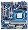
GA-880GM-UD2H/ GA-880GM-US2H AM3 socket motherboard for AMD Phenom™ II processor/AMD Athlon™ II processor User's Manual Rev. 1001 12ME-88GMU2H-1001R
GA-880GM-UD2H/ GA-880GM-US2H AM3 socket motherboard for AMD Phenom™ II processor/AMD Athlon™ II processor User's Manual Rev. 1001 12ME-88GMU2H-1001R
Manual
Page 2
Motherboard GA-880GM-UD2H/GA-880GM-US2H Mar. 5, 2010 Motherboard GA-880GM-UD2H/ GA-880GM-US2H Mar. 5, 2010
Motherboard GA-880GM-UD2H/GA-880GM-US2H Mar. 5, 2010 Motherboard GA-880GM-UD2H/ GA-880GM-US2H Mar. 5, 2010
Manual
Page 3
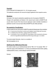
...reproduced, copied, translated, transmitted, or published in the use GIGABYTE's unique features, read the User's Manual. For example, "REV: 1.0" means the revision of GIGABYTE. For product-related information, check on our website at: http://www.gigabyte.com.tw Identifying Your Motherboard Revision The revision number on our ... Classifications In order to the specifications and features in this manual may be made by any form or by GIGABYTE without GIGABYTE's prior written permission. For instructions on how to their respective owners. All rights reserved.
...reproduced, copied, translated, transmitted, or published in the use GIGABYTE's unique features, read the User's Manual. For example, "REV: 1.0" means the revision of GIGABYTE. For product-related information, check on our website at: http://www.gigabyte.com.tw Identifying Your Motherboard Revision The revision number on our ... Classifications In order to the specifications and features in this manual may be made by any form or by GIGABYTE without GIGABYTE's prior written permission. For instructions on how to their respective owners. All rights reserved.
Manual
Page 4
Table of Contents Box Contents...6 Optional Items...6 GA-880GM-UD2H/GA-880GM-US2H Motherboard Layout 7 GA-880GM-UD2H/GA-880GM-US2H Motherboard Block Diagram 8 Chapter 1 Hardware Installation 9 1-1 Installation Precautions 9 1-2 Product Specifications 10 1-3 Installing the CPU and CPU Cooler 13 1-3-1 Installing the CPU 13 1-3-2 Installing the ...
Table of Contents Box Contents...6 Optional Items...6 GA-880GM-UD2H/GA-880GM-US2H Motherboard Layout 7 GA-880GM-UD2H/GA-880GM-US2H Motherboard Block Diagram 8 Chapter 1 Hardware Installation 9 1-1 Installation Precautions 9 1-2 Product Specifications 10 1-3 Installing the CPU and CPU Cooler 13 1-3-1 Installing the CPU 13 1-3-2 Installing the ...
Manual
Page 5
... Functionj 93 5-2-4 Configuring Microphone Recording 94 5-2-5 Using the Sound Recorder 96 5-3 Troubleshooting 97 5-3-1 Frequently Asked Questions 97 5-3-2 Troubleshooting Procedure 98 5-4 Regulatory Statements 100 j Only for GA-880GM-UD2H - 5 -
... Functionj 93 5-2-4 Configuring Microphone Recording 94 5-2-5 Using the Sound Recorder 96 5-3 Troubleshooting 97 5-3-1 Frequently Asked Questions 97 5-3-2 Troubleshooting Procedure 98 5-4 Regulatory Statements 100 j Only for GA-880GM-UD2H - 5 -
Manual
Page 6
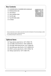
Box Contents GA-880GM-UD2H or GA-880GM-US2H motherboard Motherboard driver disk User's Manual Quick Installation Guide One IDE cable Two SATA 3Gb/s cables I/O Shield • The box contents above are subject ...
Box Contents GA-880GM-UD2H or GA-880GM-US2H motherboard Motherboard driver disk User's Manual Quick Installation Guide One IDE cable Two SATA 3Gb/s cables I/O Shield • The box contents above are subject ...
Manual
Page 7
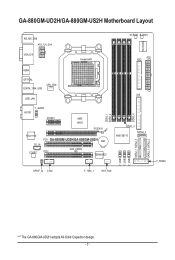
GA-880GM-UD2H/GA-880GM-US2H Motherboard Layout KB_MS_USB ATX_12V_2X4 VGA_DVI Socket AM3 M_BIOS B_BIOS ATX FDD iTE IT8720 HDMI OPTICAL ESATA_1394_USB CPU_FAN USB_LAN F_AUDIO AUDIO PCIEX1 AMD 880G PCIEX16 RTL8111D CD_IN CODEC PCI1 GA-880GM-UD2H/GA-880GM-US2H BAT CLR_CMOS PCI2 TSB43AB23 DDR3_1 DDR3_2 DDR3_4 IDE DDR3_3 AMD SB710 SATA2_4 SPDIF_IO COM F_1394_1 SYS_FAN F_USB1 F_USB2 F_USB3 SATA2_1 SATA2_3 SATA2_0 SATA2_2 F_PANEL "*" The GA-880GM-UD2H adopts All-Solid Capacitor design. - 7 -
GA-880GM-UD2H/GA-880GM-US2H Motherboard Layout KB_MS_USB ATX_12V_2X4 VGA_DVI Socket AM3 M_BIOS B_BIOS ATX FDD iTE IT8720 HDMI OPTICAL ESATA_1394_USB CPU_FAN USB_LAN F_AUDIO AUDIO PCIEX1 AMD 880G PCIEX16 RTL8111D CD_IN CODEC PCI1 GA-880GM-UD2H/GA-880GM-US2H BAT CLR_CMOS PCI2 TSB43AB23 DDR3_1 DDR3_2 DDR3_4 IDE DDR3_3 AMD SB710 SATA2_4 SPDIF_IO COM F_1394_1 SYS_FAN F_USB1 F_USB2 F_USB3 SATA2_1 SATA2_3 SATA2_0 SATA2_2 F_PANEL "*" The GA-880GM-UD2H adopts All-Solid Capacitor design. - 7 -
Manual
Page 8
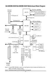
GA-880GM-UD2H/GA-880GM-US2H Motherboard Block Diagram PCIe CLK (100 MHz) 1 PCI Express x16 PCI Express x16 PCI Express Bus x1 x1 PCIe CLK (100 MHz) RTL8111D RJ45 1 ...
GA-880GM-UD2H/GA-880GM-US2H Motherboard Block Diagram PCIe CLK (100 MHz) 1 PCI Express x16 PCI Express x16 PCI Express Bus x1 x1 PCIe CLK (100 MHz) RTL8111D RJ45 1 ...
Manual
Page 9
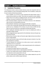
If you are uncertain about any metal leads or connectors. • It is best to wear an electrostatic discharge (ESD) wrist strap when handling electronic com- Hardware Installation ponents such as a result of electrostatic discharge (ESD). These stickers are required for warranty validation. • Always remove the AC power by your dealer. Chapter 1 Hardware Installation 1-1 Installation Precautions The motherboard contains numerous delicate electronic circuits and components which can lead to damage to system components as well as physical harm to the user. • If you do ...
If you are uncertain about any metal leads or connectors. • It is best to wear an electrostatic discharge (ESD) wrist strap when handling electronic com- Hardware Installation ponents such as a result of electrostatic discharge (ESD). These stickers are required for warranty validation. • Always remove the AC power by your dealer. Chapter 1 Hardware Installation 1-1 Installation Precautions The motherboard contains numerous delicate electronic circuits and components which can lead to damage to system components as well as physical harm to the user. • If you do ...
Manual
Page 10
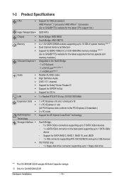
... floppy disk drive "*" The GA-880GM-UD2H adopts All-Solid Capacitor design. j Only for GA-880GM-UD2H Hardware Installation - 10 - 1-2 Product Specifications CPU Support for AM3 processors: AMD Phenom™ II processor/ AMD Athlon™ II processor (Go to GIGABYTE's website for the latest CPU... up to 16 GB of system memory (Note 1) Dual channel memory architecture Support for DDR3 1800(O.C.)/1333/1066 MHz memory modules (Note 2) (Go to GIGABYTE's website for the latest supported memory speeds and memory modules.) Integrated in the North Bridge: - 1 x D-Sub port - 1 x DVI-D port ...
... floppy disk drive "*" The GA-880GM-UD2H adopts All-Solid Capacitor design. j Only for GA-880GM-UD2H Hardware Installation - 10 - 1-2 Product Specifications CPU Support for AM3 processors: AMD Phenom™ II processor/ AMD Athlon™ II processor (Go to GIGABYTE's website for the latest CPU... up to 16 GB of system memory (Note 1) Dual channel memory architecture Support for DDR3 1800(O.C.)/1333/1066 MHz memory modules (Note 2) (Go to GIGABYTE's website for the latest supported memory speeds and memory modules.) Integrated in the North Bridge: - 1 x D-Sub port - 1 x DVI-D port ...
Manual
Page 11
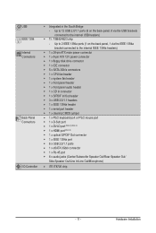
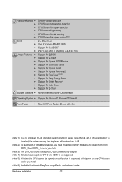
TSB43AB23 chip - Up to 2 IEEE 1394a ports (1 on the back panel, 6 via the IEEE 1394a bracket connected to the internal USB headers) IEEE 1394 T.I /O Controller w iTE IT8720 chip - 11 - USB Integrated in the South Bridge - Up to 12 USB 2.0/1.1 ports (6 on the back panel, 1 via the USB brackets connected to the internal IEEE 1394a headers) Internal w 1 x 24-pin ATX main power connector Connectors w 1 x 8-pin ATX 12V power connector w 1 x floppy disk drive connector w 1 x IDE connector w 5 x SATA 3Gb/s ...
TSB43AB23 chip - Up to 2 IEEE 1394a ports (1 on the back panel, 6 via the IEEE 1394a bracket connected to the internal USB headers) IEEE 1394 T.I /O Controller w iTE IT8720 chip - 11 - USB Integrated in the South Bridge - Up to 12 USB 2.0/1.1 ports (6 on the back panel, 1 via the USB brackets connected to the internal IEEE 1394a headers) Internal w 1 x 24-pin ATX main power connector Connectors w 1 x 8-pin ATX 12V power connector w 1 x floppy disk drive connector w 1 x IDE connector w 5 x SATA 3Gb/s ...
Manual
Page 12
Hardware Installation - 12 - Hardware Monitor w w w w w w BIOS w w w w Unique Features w w w w w w w w w w w Bundled Software w System voltage detection CPU/System temperature detection CPU/System fan speed detection CPU overheating warning CPU/System fan fail warning CPU/System fan speed control (Note 5) 2 x 8 Mbit flash Use of licensed AWARD BIOS Support for DualBIOS™ PnP 1.0a, DMI 2.0, SM BIOS 2.4, ACPI 1.0b Support for @BIOS Support for Q-Flash Support for Xpress BIOS ...
Hardware Installation - 12 - Hardware Monitor w w w w w w BIOS w w w w Unique Features w w w w w w w w w w w Bundled Software w System voltage detection CPU/System temperature detection CPU/System fan speed detection CPU overheating warning CPU/System fan fail warning CPU/System fan speed control (Note 5) 2 x 8 Mbit flash Use of licensed AWARD BIOS Support for DualBIOS™ PnP 1.0a, DMI 2.0, SM BIOS 2.4, ACPI 1.0b Support for @BIOS Support for Q-Flash Support for Xpress BIOS ...
Manual
Page 13
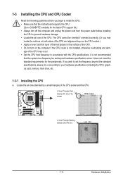
... latest CPU support list.) • Always turn on the computer if the CPU cooler is not recommended that the motherboard supports the CPU. (Go to GIGABYTE's website for the peripherals. It is not installed, otherwise overheating and dam- Locate the pin one of the CPU. Hardware Installation A Small Triangle Mark Denotes...
... latest CPU support list.) • Always turn on the computer if the CPU cooler is not recommended that the motherboard supports the CPU. (Go to GIGABYTE's website for the peripherals. It is not installed, otherwise overheating and dam- Locate the pin one of the CPU. Hardware Installation A Small Triangle Mark Denotes...
Manual
Page 14
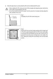
CPU Socket Locking Lever Step 1: Completely lift up the CPU socket locking lever. Make sure that the CPU pins fit perfectly into the CPU socket. B. The CPU cannot fit in if oriented incorrectly. Adjust the CPU orientation if this occurs. Once the CPU is positioned into its socket, place one (small triangle marking) with the triangle mark on the middle of the CPU, lowering the locking lever and latching it into the socket. Follow the steps below to correctly install the CPU into the motherboard CPU socket. • Before installing the CPU, make sure to turn off the ...
CPU Socket Locking Lever Step 1: Completely lift up the CPU socket locking lever. Make sure that the CPU pins fit perfectly into the CPU socket. B. The CPU cannot fit in if oriented incorrectly. Adjust the CPU orientation if this occurs. Once the CPU is positioned into its socket, place one (small triangle marking) with the triangle mark on the middle of the CPU, lowering the locking lever and latching it into the socket. Follow the steps below to correctly install the CPU into the motherboard CPU socket. • Before installing the CPU, make sure to turn off the ...
Manual
Page 15
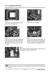
1-3-2 Installing the CPU Cooler Follow the steps below to correctly install the CPU cooler on the CPU. (The following procedure uses the GIGABYTE cooler as the picture above shows) to lock into place. (Refer to your CPU cooler installation manual for instructions on installing the cooler.) Step 5: Finally, ...
1-3-2 Installing the CPU Cooler Follow the steps below to correctly install the CPU cooler on the CPU. (The following procedure uses the GIGABYTE cooler as the picture above shows) to lock into place. (Refer to your CPU cooler installation manual for instructions on installing the cooler.) Step 5: Finally, ...
Manual
Page 16
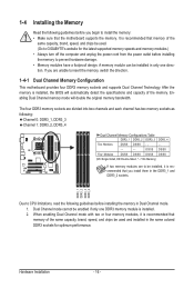
... guidelines before you begin to install the memory: • Make sure that memory of the same capacity, brand, speed, and chips be used . (Go to GIGABYTE's website for optimum performance. It is recommended that you install them in the same colored DDR3 sockets for the latest supported memory speeds and memory...
... guidelines before you begin to install the memory: • Make sure that memory of the same capacity, brand, speed, and chips be used . (Go to GIGABYTE's website for optimum performance. It is recommended that you install them in the same colored DDR3 sockets for the latest supported memory speeds and memory...
Manual
Page 17
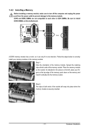
DDR3 and DDR2 DIMMs are not compatible to each other or DDR DIMMs. Be sure to install DDR3 DIMMs on the socket. As indicated in one direction. Notch DDR3 DIMM A DDR3 memory module has a notch, so it can only fit in the picture on the memory and insert it vertically into place when the memory module is securely inserted. - 17 - Step 1: Note the orientation of the socket will snap into the memory socket. Follow the steps below to the memory module. Place the memory module on this motherboard. Spread the retaining clips at both ends of the memory, push down on the left,...
DDR3 and DDR2 DIMMs are not compatible to each other or DDR DIMMs. Be sure to install DDR3 DIMMs on the socket. As indicated in one direction. Notch DDR3 DIMM A DDR3 memory module has a notch, so it can only fit in the picture on the memory and insert it vertically into place when the memory module is securely inserted. - 17 - Step 1: Note the orientation of the socket will snap into the memory socket. Follow the steps below to the memory module. Place the memory module on this motherboard. Spread the retaining clips at both ends of the memory, push down on the left,...
Manual
Page 18
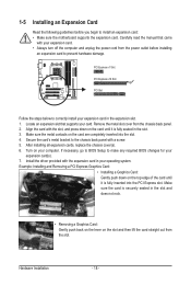
Secure the card's metal bracket to the chassis back panel with the expansion card in the slot and does not rock. • Removing a Graphics Card: Gently push back on the lever on the card are completely inserted into the PCI Express slot. Install the driver provided with a screw. 5. 1-5 Installing an Expansion Card Read the following guidelines before installing an expansion card to prevent hardware damage. Example: Installing and Removing a PCI Express Graphics Card: • Installing a Graphics Card: Gently push down on your expansion card(s). 7. Remove the metal slot ...
Secure the card's metal bracket to the chassis back panel with the expansion card in the slot and does not rock. • Removing a Graphics Card: Gently push back on the lever on the card are completely inserted into the PCI Express slot. Install the driver provided with a screw. 5. 1-5 Installing an Expansion Card Read the following guidelines before installing an expansion card to prevent hardware damage. Example: Installing and Removing a PCI Express Graphics Card: • Installing a Graphics Card: Gently push down on your expansion card(s). 7. Remove the metal slot ...
Manual
Page 19
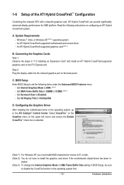
System Requirements - An ATI Hybrid CrossFireX-supported graphics card (Note 2) B. C. Set Internal Graphics Mode to OnChipVGA. Set Init Display First to UMA. (Note 3) - Set Surround View to 256MB or 512MB. (Note 3) - 1-6 Setup of the ATI Hybrid CrossFireX™ Configuration Combining the onboard GPU with a discrete graphics card, ATI Hybrid CrossFireX can provide significantly advanced display performance for AMD platform. Read the following items under the Advanced BIOS Features menu: - stalled. (Note 3) To change the Internal Graphics Mode or UMA Frame ...
System Requirements - An ATI Hybrid CrossFireX-supported graphics card (Note 2) B. C. Set Internal Graphics Mode to OnChipVGA. Set Init Display First to UMA. (Note 3) - Set Surround View to 256MB or 512MB. (Note 3) - 1-6 Setup of the ATI Hybrid CrossFireX™ Configuration Combining the onboard GPU with a discrete graphics card, ATI Hybrid CrossFireX can provide significantly advanced display performance for AMD platform. Read the following items under the Advanced BIOS Features menu: - stalled. (Note 3) To change the Internal Graphics Mode or UMA Frame ...
Manual
Page 20
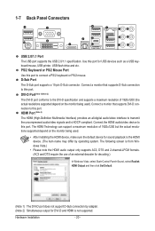
D-Sub Port The D-Sub port supports a 15-pin D-Sub connector. HDMI Port (Note 2) The HDMI (High-Definition Multimedia Interface) provides an all-digital audio/video interface to this port. The following screen is the HDMI device. (The item name may differ by adapter. (Note 2) Simultaneous output for USB devices such as a USB keyboard/mouse, USB printer, USB flash drive and etc. Connect a monitor that supports DVI-D connection to the DVI-D specification and supports a maximum resolution of 1920x1200 but the actual resolutions supported depend on the monitor being used ). ...
D-Sub Port The D-Sub port supports a 15-pin D-Sub connector. HDMI Port (Note 2) The HDMI (High-Definition Multimedia Interface) provides an all-digital audio/video interface to this port. The following screen is the HDMI device. (The item name may differ by adapter. (Note 2) Simultaneous output for USB devices such as a USB keyboard/mouse, USB printer, USB flash drive and etc. Connect a monitor that supports DVI-D connection to the DVI-D specification and supports a maximum resolution of 1920x1200 but the actual resolutions supported depend on the monitor being used ). ...
