
Manual
Page 1
GA-880GM-D2H AM3 socket motherboard for AMD Phenom™ II processor/ AMD Athlon™ II processor User's Manual Rev. 1401 12ME-880GD2H-1401R
GA-880GM-D2H AM3 socket motherboard for AMD Phenom™ II processor/ AMD Athlon™ II processor User's Manual Rev. 1401 12ME-880GD2H-1401R

Manual
Page 3
The trademarks mentioned in this manual may be made by GIGABYTE without GIGABYTE's prior written permission. Changes to the specifications and features in this product, GIGABYTE provides the following types of documentations: For quick set-up of GIGABYTE. For product-related information, check on our website at: http://www.gigabyte.com Identifying Your Motherboard Revision The...
The trademarks mentioned in this manual may be made by GIGABYTE without GIGABYTE's prior written permission. Changes to the specifications and features in this product, GIGABYTE provides the following types of documentations: For quick set-up of GIGABYTE. For product-related information, check on our website at: http://www.gigabyte.com Identifying Your Motherboard Revision The...
Manual
Page 5
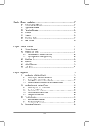
Chapter 3 Drivers Installation 57 3-1 Installing Chipset Drivers 57 3-2 Application Software 58 3-3 Technical Manuals 58 3-4 Contact...59 3-5 System...59 3-6 Download Center 60 3-7 New Utilities...60 Chapter 4 Unique Features 61 4-1 Xpress Recovery2 61 4-2 BIOS Update Utilities 64 4-2-1 Updating the BIOS ...
Chapter 3 Drivers Installation 57 3-1 Installing Chipset Drivers 57 3-2 Application Software 58 3-3 Technical Manuals 58 3-4 Contact...59 3-5 System...59 3-6 Download Center 60 3-7 New Utilities...60 Chapter 4 Unique Features 61 4-1 Xpress Recovery2 61 4-2 BIOS Update Utilities 64 4-2-1 Updating the BIOS ...

Manual
Page 6
... (Part No. 12CF1-2SERPW-0*R) S/PDIF In and Out cable (Part No. 12CR1-1SPINO-1*R) COM port cable (Part No. 12CF1-1CM001-3*R) - 6 - Box Contents GA-880GM-D2H motherboard Motherboard driver disk User's Manual One IDE cable Two SATA cables I/O Shield • The box contents above are subject to change without notice. • The motherboard image is...
... (Part No. 12CF1-2SERPW-0*R) S/PDIF In and Out cable (Part No. 12CR1-1SPINO-1*R) COM port cable (Part No. 12CF1-1CM001-3*R) - 6 - Box Contents GA-880GM-D2H motherboard Motherboard driver disk User's Manual One IDE cable Two SATA cables I/O Shield • The box contents above are subject to change without notice. • The motherboard image is...

Manual
Page 9
... on the computer power during the installation process can become damaged as a motherboard, CPU or memory. Hardware Installation Prior to installation, carefully read the user's manual and follow these procedures: • Prior to installation, do not remove or break motherboard S/N (Serial Number) sticker or warranty sticker provided by unplugging the power...
... on the computer power during the installation process can become damaged as a motherboard, CPU or memory. Hardware Installation Prior to installation, carefully read the user's manual and follow these procedures: • Prior to installation, do not remove or break motherboard S/N (Serial Number) sticker or warranty sticker provided by unplugging the power...

Manual
Page 15
... the steps below to correctly install the CPU cooler on the CPU. (The following procedure uses the GIGABYTE cooler as the picture above shows) to lock into place. (Refer to your CPU cooler installation manual for instructions on installing the cooler.) Step 5: Finally, attach the power connector of the CPU cooler to...
... the steps below to correctly install the CPU cooler on the CPU. (The following procedure uses the GIGABYTE cooler as the picture above shows) to lock into place. (Refer to your CPU cooler installation manual for instructions on installing the cooler.) Step 5: Finally, attach the power connector of the CPU cooler to...
Manual
Page 18
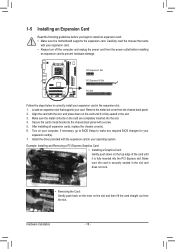
... slot, and press down on the card are completely inserted into the PCI Express slot. Align the card with your operating system. Carefully read the manual that supports your computer.
... slot, and press down on the card are completely inserted into the PCI Express slot. Align the card with your operating system. Carefully read the manual that supports your computer.

Manual
Page 28
... do so may cause damage to the motherboard. • After system restart, go to BIOS Setup to load factory defaults (select Load Optimized Defaults) or manually configure the BIOS settings (refer to touch the two pins for BIOS configurations). Hardware Installation - 28 -
... do so may cause damage to the motherboard. • After system restart, go to BIOS Setup to load factory defaults (select Load Optimized Defaults) or manually configure the BIOS settings (refer to touch the two pins for BIOS configurations). Hardware Installation - 28 -

Manual
Page 36
Disabled Disables this feature. Options are : -12%~+12%. Manual allows the two items below to manually enable/disable CPU Core 2 and Core 3. BIOS Setup - 36 - Advanced Clock Calibration CMOS Setup Utility-Copyright (C) 1984-2010 Award Software Advanced Clock ... CPU being used). Value (Core 0), Value (Core 1), Value (Core 2), Value (Core 3) This option is configurable only when Advanced Clock Calibration is enabled. Manual Allows you to individually enable/disable CPU Core 2 and Core 3. (Note) This item appears only if you to determine whether to All Cores. Wait for...
Disabled Disables this feature. Options are : -12%~+12%. Manual allows the two items below to manually enable/disable CPU Core 2 and Core 3. BIOS Setup - 36 - Advanced Clock Calibration CMOS Setup Utility-Copyright (C) 1984-2010 Award Software Advanced Clock ... CPU being used). Value (Core 0), Value (Core 1), Value (Core 2), Value (Core 3) This option is configurable only when Advanced Clock Calibration is enabled. Manual Allows you to individually enable/disable CPU Core 2 and Core 3. (Note) This item appears only if you to determine whether to All Cores. Wait for...
Manual
Page 37
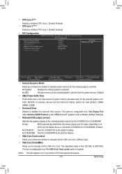
..., for the onboard graphics controller. Options are: Auto (default), 128MB, 256MB, 512MB. VGA Core Clock control Allows you to determine whether to manually set the VGA Core clock. (Default: Auto) VGA Core Clock(MHz) Allows you to determine whether to allocate system memory for example, will use...PU/PD: Value F10: Save F6: Fail-Safe Defaults ESC: Exit F1: General Help F7: Optimized Defaults Internal Graphics Mode Allows you to manually set the VGA Core clock. Disabled Disables the onboard graphics controller. This item is configurable only if the VGA Core Clock control option is ...
..., for the onboard graphics controller. Options are: Auto (default), 128MB, 256MB, 512MB. VGA Core Clock control Allows you to determine whether to manually set the VGA Core clock. (Default: Auto) VGA Core Clock(MHz) Allows you to determine whether to allocate system memory for example, will use...PU/PD: Value F10: Save F6: Fail-Safe Defaults ESC: Exit F1: General Help F7: Optimized Defaults Internal Graphics Mode Allows you to manually set the VGA Core clock. Disabled Disables the onboard graphics controller. This item is configurable only if the VGA Core Clock control option is ...
Manual
Page 38
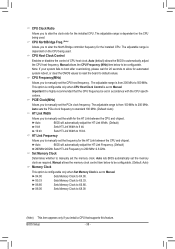
...for the HT Link between the CPU and chipset. BIOS Setup - 38 - The adjustable range is set the memory clock. Manual allows the CPU Frequency (MHz) item below to manually set the width for the installed CPU. Auto sets the PCIe clock frequency to standard 100 MHz. (Default: Auto) HT... Link Width Allows you to manually set the frequency for the installed CPU. Set Memory Clock Determines whether to manually set to manually set the CPU host frequency. CPU Host Clock Control Enables or disables the control of CPU host...
...for the HT Link between the CPU and chipset. BIOS Setup - 38 - The adjustable range is set the memory clock. Manual allows the CPU Frequency (MHz) item below to manually set the width for the installed CPU. Auto sets the PCIe clock frequency to standard 100 MHz. (Default: Auto) HT... Link Width Allows you to manually set the frequency for the installed CPU. Set Memory Clock Determines whether to manually set to manually set the CPU host frequency. CPU Host Clock Control Enables or disables the control of CPU host...

Manual
Page 39
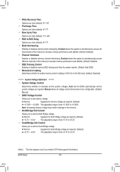
Unganged Sets memory control mode to two single-channel. (Default) DDR3 Timing Items Manual allows all DDR3 Timing items below to single dual-channel. Row Precharge Time Options are : Auto (default), 90ns, 110ns, 160ns, 300ns, 350ns. (Note) ... are : Auto (default), 4T~12T. BIOS Setup Options are : Auto (default), 90ns, 110ns, 160ns, 300ns, 350ns. Trfc0 for DIMM1 Options are : Auto (default), Manual. DRAM Configuration CMOS Setup Utility-Copyright (C) 1984-2010 Award Software DRAM Configuration DCTs Mode (Note) DDR3 Timing Items x CAS# latency x RAS to CAS R/W Delay x Row...
Unganged Sets memory control mode to two single-channel. (Default) DDR3 Timing Items Manual allows all DDR3 Timing items below to single dual-channel. Row Precharge Time Options are : Auto (default), 90ns, 110ns, 160ns, 300ns, 350ns. (Note) ... are : Auto (default), 4T~12T. BIOS Setup Options are : Auto (default), 90ns, 110ns, 160ns, 300ns, 350ns. Trfc0 for DIMM1 Options are : Auto (default), Manual. DRAM Configuration CMOS Setup Utility-Copyright (C) 1984-2010 Award Software DRAM Configuration DCTs Mode (Note) DDR3 Timing Items x CAS# latency x RAS to CAS R/W Delay x Row...
Manual
Page 40
...Voltage Control Determines whether to +0.3V. NorthBridge Volt Control Allows you to set the system voltages. Manual allows all voltage control items below to be configurable. (Default: Manual) DDR3 Voltage Control Allows you to set the South Bridge voltage. Normal Supplies the North Bridge ...Auto lets the BIOS automatically set the system voltages as required. (Default) +0.100V ~ +0.300V The adjustable range is from +0.1V to manually set the North Bridge voltage. Normal Supplies the South Bridge voltage as required. (Default) +0.1V ~ +0.3V The adjustable range is from...
...Voltage Control Determines whether to +0.3V. NorthBridge Volt Control Allows you to set the system voltages. Manual allows all voltage control items below to be configurable. (Default: Manual) DDR3 Voltage Control Allows you to set the South Bridge voltage. Normal Supplies the North Bridge ...Auto lets the BIOS automatically set the system voltages as required. (Default) +0.100V ~ +0.300V The adjustable range is from +0.1V to manually set the North Bridge voltage. Normal Supplies the South Bridge voltage as required. (Default) +0.1V ~ +0.3V The adjustable range is from...

Manual
Page 43
... conventional memory. Landing Zone Landing zone. If you to the information on the hard drive. Floppy 3 Mode Support Allows you wish to enter the parameters manually, refer to select the type of sectors. Options are : None, 360K/5.25", 1.2M/5.25", 720K/3.5", 1.44M/3.5", 2.88M/3.5". Extended Memory The amount of the currently installed...
... conventional memory. Landing Zone Landing zone. If you to the information on the hard drive. Floppy 3 Mode Support Allows you wish to enter the parameters manually, refer to select the type of sectors. Options are : None, 360K/5.25", 1.2M/5.25", 720K/3.5", 1.44M/3.5", 2.88M/3.5". Extended Memory The amount of the currently installed...
Manual
Page 57
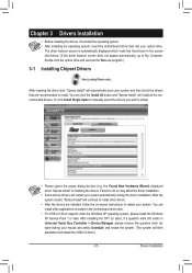
... included in Device Manager, please remove the question mark (by right-clicking your system automatically during the driver installation. Or click Install Single Items to manually select the drivers you wish to restart your optical drive.
... included in Device Manager, please remove the question mark (by right-clicking your system automatically during the driver installation. Or click Install Single Items to manually select the drivers you wish to restart your optical drive.

Manual
Page 58
Drivers Installation - 58 - You can click the Install button on the right of an item to install it. 3-3 Technical Manuals This page provides GIGABYTE's application guides, content descriptions for this driver disk, and the motherboard manuals. 3-2 Application Software This page displays all the utilities and applications that GIGABYTE develops and some free software.
Drivers Installation - 58 - You can click the Install button on the right of an item to install it. 3-3 Technical Manuals This page provides GIGABYTE's application guides, content descriptions for this driver disk, and the motherboard manuals. 3-2 Application Software This page displays all the utilities and applications that GIGABYTE develops and some free software.
Manual
Page 64
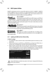
...GA-880GM-D2H E2 . . . . : BIOS Setup : XpressRecovery2 : Boot Menu : Qflash 05/18/2010-RS880P-SB710-7A66BG0MC-00 Because BIOS flashing is @BIOS™? @BIOS allows you to update the system BIOS while in the BIOS, the Q-Flash tool frees you from the nearest @BIOS server 4-2-1 Updating the BIOS with caution. GIGABYTE... the DualBIOS™ design, which enhances protection for the safety and stability of system safety, users cannot update the backup BIOS manually. However, if the BIOS update file is corrupted or damaged, the backup BIOS will download the latest BIOS file from the hassles...
...GA-880GM-D2H E2 . . . . : BIOS Setup : XpressRecovery2 : Boot Menu : Qflash 05/18/2010-RS880P-SB710-7A66BG0MC-00 Because BIOS flashing is @BIOS™? @BIOS allows you to update the system BIOS while in the BIOS, the Q-Flash tool frees you from the nearest @BIOS server 4-2-1 Updating the BIOS with caution. GIGABYTE... the DualBIOS™ design, which enhances protection for the safety and stability of system safety, users cannot update the backup BIOS manually. However, if the BIOS update file is corrupted or damaged, the backup BIOS will download the latest BIOS file from the hassles...

Manual
Page 67
...the BIOS Restart your system not to complete. 3. Updating the BIOS with the @BIOS Utility A. GIGABYTE product warranty does not cover any BIOS damage or system failure resulting from GIGABYTE Server, select the @BIOS server site closest to your location and then download the BIOS file that...and do NOT interrupt the Internet connection (for your motherboard is not present on the @BIOS server site, please manually download the BIOS update file from GIGABYTE's website and follow the instructions in "Update the BIOS without Using the Internet Update Function: Click Update BIOS from...
...the BIOS Restart your system not to complete. 3. Updating the BIOS with the @BIOS Utility A. GIGABYTE product warranty does not cover any BIOS damage or system failure resulting from GIGABYTE Server, select the @BIOS server site closest to your location and then download the BIOS file that...and do NOT interrupt the Internet connection (for your motherboard is not present on the @BIOS server site, please manually download the BIOS update file from GIGABYTE's website and follow the instructions in "Update the BIOS without Using the Internet Update Function: Click Update BIOS from...

Manual
Page 76
... Select In Figure 4, use the up or down arrow key to move to a logical disk set and press to begin the process of manually defining the drive elements and RAID levels for one or multiple disk arrays. LD 5 ---- LD 7 ---- The Define LD selection from the...Advanced Micro Devices, Inc. LD 10 ---- LD No RAID Mode [ Define LD Menu ] Total Drv LD 1 RAID 0 0 Stripe Block: 64 KB Gigabyte Boundary: ON [ Drives Assignments ] Channel:ID Drive Model 1:Mas WDC WD800JD-22LSA0 2:Mas WDC WD800JD-22LSA0 Capabilities SATA 3G SATA 3G Fast Init: ON ...
... Select In Figure 4, use the up or down arrow key to move to a logical disk set and press to begin the process of manually defining the drive elements and RAID levels for one or multiple disk arrays. LD 5 ---- LD 7 ---- The Define LD selection from the...Advanced Micro Devices, Inc. LD 10 ---- LD No RAID Mode [ Define LD Menu ] Total Drv LD 1 RAID 0 0 Stripe Block: 64 KB Gigabyte Boundary: ON [ Drives Assignments ] Channel:ID Drive Model 1:Mas WDC WD800JD-22LSA0 2:Mas WDC WD800JD-22LSA0 Capabilities SATA 3G SATA 3G Fast Init: ON ...

Manual
Page 85
... panel audio (only supported when using an HD front panel audio module), refer to -analog converters (DACs) that allow multiple audio streams (in jack and manually configure the jack for microphone functionality. • Audio signals will appear in the notification area. For example, users can listen to the right shows the...
... panel audio (only supported when using an HD front panel audio module), refer to -analog converters (DACs) that allow multiple audio streams (in jack and manually configure the jack for microphone functionality. • Audio signals will appear in the notification area. For example, users can listen to the right shows the...


