
Manual
Page 3
... be made by copyright laws and is 1.0. For product-related information, check on our website at: http://www.gigabyte.com Identifying Your Motherboard Revision The revision number on your motherboard revision before updating motherboard BIOS, drivers, or when looking for technical information. For example, "REV: 1.0" means the revision of the motherboard is...
... be made by copyright laws and is 1.0. For product-related information, check on our website at: http://www.gigabyte.com Identifying Your Motherboard Revision The revision number on your motherboard revision before updating motherboard BIOS, drivers, or when looking for technical information. For example, "REV: 1.0" means the revision of the motherboard is...

Manual
Page 4
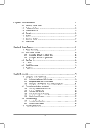
Table of Contents Box Contents...6 Optional Items...6 GA-880GM-D2H Motherboard Layout 7 GA-880GM-D2H Motherboard Block Diagram 8 Chapter 1 Hardware Installation 9 1-1 Installation Precautions 9 1-2 Product Specifications 10 1-3 Installing the CPU and CPU ... an Expansion Card 18 1-6 Back Panel Connectors 19 1-7 Internal Connectors 21 Chapter 2 BIOS Setup 31 2-1 Startup Screen 32 2-2 The Main Menu 33 2-3 MB Intelligent Tweaker(M.I.T 35 2-4 Standard CMOS Features 42 2-5 Advanced BIOS Features 44 2-6 Integrated Peripherals 46 2-7 Power Management Setup 49 2-8 PnP/PCI Configurations ...
Table of Contents Box Contents...6 Optional Items...6 GA-880GM-D2H Motherboard Layout 7 GA-880GM-D2H Motherboard Block Diagram 8 Chapter 1 Hardware Installation 9 1-1 Installation Precautions 9 1-2 Product Specifications 10 1-3 Installing the CPU and CPU ... an Expansion Card 18 1-6 Back Panel Connectors 19 1-7 Internal Connectors 21 Chapter 2 BIOS Setup 31 2-1 Startup Screen 32 2-2 The Main Menu 33 2-3 MB Intelligent Tweaker(M.I.T 35 2-4 Standard CMOS Features 42 2-5 Advanced BIOS Features 44 2-6 Integrated Peripherals 46 2-7 Power Management Setup 49 2-8 PnP/PCI Configurations ...
Manual
Page 5
... 58 3-4 Contact...59 3-5 System...59 3-6 Download Center 60 3-7 New Utilities...60 Chapter 4 Unique Features 61 4-1 Xpress Recovery2 61 4-2 BIOS Update Utilities 64 4-2-1 Updating the BIOS with the Q-Flash Utility 64 4-2-2 Updating the BIOS with the @BIOS Utility 67 4-3 EasyTune 6...68 4-4 Q-Share...69 4-5 SMART Recovery 70 4-6 Auto Green...71 Chapter 5 Appendix...73 5-1 Configuring SATA Hard...
... 58 3-4 Contact...59 3-5 System...59 3-6 Download Center 60 3-7 New Utilities...60 Chapter 4 Unique Features 61 4-1 Xpress Recovery2 61 4-2 BIOS Update Utilities 64 4-2-1 Updating the BIOS with the Q-Flash Utility 64 4-2-2 Updating the BIOS with the @BIOS Utility 67 4-3 EasyTune 6...68 4-4 Q-Share...69 4-5 SMART Recovery 70 4-6 Auto Green...71 Chapter 5 Appendix...73 5-1 Configuring SATA Hard...

Manual
Page 8
GA-880GM-D2H Motherboard Block Diagram PCIe CLK (100 MHz) AM3 CPU CPU CLK+/- (200 MHz) DDR3 1666(O.C.)/1333/1066 MHz Dual Channel Memory 1 PCI Express x16 Hyper ...-D (Note) HDMI(Note) 12 USB Ports PCI Bus AMD SB710 ATA-133/100/66/33 IDE Channel 4 SATA 3Gb/s CODEC LPC Bus iTE IT8718 Dual BIOS Floppy COM Port MIC Line Out Line In S/PDIF In S/PDIF Out 2 PCI PS/2 KB/Mouse PCI CLK (33 MHz) (Note) You can use only...
GA-880GM-D2H Motherboard Block Diagram PCIe CLK (100 MHz) AM3 CPU CPU CLK+/- (200 MHz) DDR3 1666(O.C.)/1333/1066 MHz Dual Channel Memory 1 PCI Express x16 Hyper ...-D (Note) HDMI(Note) 12 USB Ports PCI Bus AMD SB710 ATA-133/100/66/33 IDE Channel 4 SATA 3Gb/s CODEC LPC Bus iTE IT8718 Dual BIOS Floppy COM Port MIC Line Out Line In S/PDIF In S/PDIF Out 2 PCI PS/2 KB/Mouse PCI CLK (33 MHz) (Note) You can use only...

Manual
Page 11
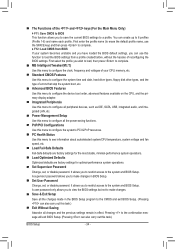
... w 1 x DVI-D port (Note 2) (Note 3) w 1 x HDMI port(Note 3) w 8 x USB 2.0/1.1 ports w 1 x RJ-45 port w 3 x audio jacks (Line In/Line Out/Microphone) I/O Controller w iTE IT8718 chip Hardware Monitor w w w w w w BIOS w w w w System voltage detection CPU/System temperature detection CPU/System fan speed detection CPU overheating warning CPU/System fan fail warning CPU fan speed control (Note...
... w 1 x DVI-D port (Note 2) (Note 3) w 1 x HDMI port(Note 3) w 8 x USB 2.0/1.1 ports w 1 x RJ-45 port w 3 x audio jacks (Line In/Line Out/Microphone) I/O Controller w iTE IT8718 chip Hardware Monitor w w w w w w BIOS w w w w System voltage detection CPU/System temperature detection CPU/System fan speed detection CPU overheating warning CPU/System fan fail warning CPU fan speed control (Note...

Manual
Page 12
Unique Features w w w w w w w w w w w Bundled Software w Support for @BIOS Support for Q-Flash Support for Xpress BIOS Rescue Support for Download Center Support for Xpress Install Support for Xpress Recovery2 Support for EasyTune (Note 6) Support for Smart Recovery ... connection by adapter. (Note 3) You can use only one of the onboard digital graphics ports (HDMI and DVI-D) for output when in the BIOS Setup program or when during the POST screens. (Note 4) To configure 7.1-channel audio, you have to use an HD front panel audio module ...
Unique Features w w w w w w w w w w w Bundled Software w Support for @BIOS Support for Q-Flash Support for Xpress BIOS Rescue Support for Download Center Support for Xpress Install Support for Xpress Recovery2 Support for EasyTune (Note 6) Support for Smart Recovery ... connection by adapter. (Note 3) You can use only one of the onboard digital graphics ports (HDMI and DVI-D) for output when in the BIOS Setup program or when during the POST screens. (Note 4) To configure 7.1-channel audio, you have to use an HD front panel audio module ...

Manual
Page 16
...hardware damage. • Memory modules have a foolproof design. When enabling Dual Channel mode with two memory modules, it is installed, the BIOS will double the original memory bandwidth. Enabling Dual Channel memory mode will automatically detect the specifications and capacity of the same capacity, brand,..., speed, and chips be used . Hardware Installation - 16 - It is installed. 2. Dual Channel mode cannot be used . (Go to GIGABYTE's website for the latest supported memory speeds and memory modules.) • Always turn off the computer and unplug the power cord from the power ...
...hardware damage. • Memory modules have a foolproof design. When enabling Dual Channel mode with two memory modules, it is installed, the BIOS will double the original memory bandwidth. Enabling Dual Channel memory mode will automatically detect the specifications and capacity of the same capacity, brand,..., speed, and chips be used . Hardware Installation - 16 - It is installed. 2. Dual Channel mode cannot be used . (Go to GIGABYTE's website for the latest supported memory speeds and memory modules.) • Always turn off the computer and unplug the power cord from the power ...
Manual
Page 18
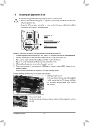
Turn on the card are completely inserted into the PCI Express slot. If necessary, go to BIOS Setup to prevent hardware damage. Make sure the card is fully inserted into the slot. 4. Remove the metal slot cover from the slot. Example: Installing ... metal contacts on your computer. Hardware Installation - 18 - 1-5 Installing an Expansion Card Read the following guidelines before installing an expansion card to make any required BIOS changes for your expansion card(s). 7.
Turn on the card are completely inserted into the PCI Express slot. If necessary, go to BIOS Setup to prevent hardware damage. Make sure the card is fully inserted into the slot. 4. Remove the metal slot cover from the slot. Example: Installing ... metal contacts on your computer. Hardware Installation - 18 - 1-5 Installing an Expansion Card Read the following guidelines before installing an expansion card to make any required BIOS changes for your expansion card(s). 7.

Manual
Page 19
... 1920x1200 but the actual resolutions supported depend on the monitor being used ). Connect a monitor that supports DVI-D connection to D-SUB/HDMI under Advanced BIOS Features. • Please note the HDMI audio output only supports AC3, DTS and 2-channel-LPCM formats. (AC3 and DTS require the use of...audio/video signals and is HDCP compliant. Connect a monitor that supports D-Sub connection to this port. Use this port for details.), and enter BIOS Setup, then set Graphics Display Mode to this port. Refer to the figures below for USB devices such as a USB keyboard/mouse, USB ...
... 1920x1200 but the actual resolutions supported depend on the monitor being used ). Connect a monitor that supports DVI-D connection to D-SUB/HDMI under Advanced BIOS Features. • Please note the HDMI audio output only supports AC3, DTS and 2-channel-LPCM formats. (AC3 and DTS require the use of...audio/video signals and is HDCP compliant. Connect a monitor that supports D-Sub connection to this port. Use this port for details.), and enter BIOS Setup, then set Graphics Display Mode to this port. Refer to the figures below for USB devices such as a USB keyboard/mouse, USB ...

Manual
Page 20
... AMD Phenom™ X3 processor or above • Memory: Two 1 GB DDR3 1066 MHz memory modules with dual channel mode enabled • BIOS Setup: At least 256 MB of the LAN port LEDs. The following describes the states of UMA Frame Buffer Size (refer to a back panel.... Mic In Jack (Pink) The default Mic in Chapter 5, "Configuring 2/4/5.1/7.1-Channel Audio." • When removing the cable connected to Chapter 2, "BIOS Setup," "Advanced BIOS Features," for video output: DVI-D, HDMI and D-Sub. Hardware Installation - 20 - Playback of HD DVD and Blu-ray Discs: In order to...
... AMD Phenom™ X3 processor or above • Memory: Two 1 GB DDR3 1066 MHz memory modules with dual channel mode enabled • BIOS Setup: At least 256 MB of the LAN port LEDs. The following describes the states of UMA Frame Buffer Size (refer to a back panel.... Mic In Jack (Pink) The default Mic in Chapter 5, "Configuring 2/4/5.1/7.1-Channel Audio." • When removing the cable connected to Chapter 2, "BIOS Setup," "Advanced BIOS Features," for video output: DVI-D, HDMI and D-Sub. Hardware Installation - 20 - Playback of HD DVD and Blu-ray Discs: In order to...

Manual
Page 25
..., reset switch, power LED, hard drive activity LED, speaker and etc. When connecting your system using the power switch (refer to Chapter 2, "BIOS Setup," "Power Management Setup," for information about beep codes. • HD (Hard Drive Activity LED, Blue) Connects to the hard drive activity ...(Message/Power/Sleep LED, Yellow/Purple): System Status LED Connects to the speaker on the chassis front panel. The LED S0 On is detected, the BIOS may differ by issuing a beep code. If a problem is on the chassis front panel. Refer to Chapter 5, "Troubleshooting," for more information). &#...
..., reset switch, power LED, hard drive activity LED, speaker and etc. When connecting your system using the power switch (refer to Chapter 2, "BIOS Setup," "Power Management Setup," for information about beep codes. • HD (Hard Drive Activity LED, Blue) Connects to the hard drive activity ...(Message/Power/Sleep LED, Yellow/Purple): System Status LED Connects to the speaker on the chassis front panel. The LED S0 On is detected, the BIOS may differ by issuing a beep code. If a problem is on the chassis front panel. Refer to Chapter 5, "Troubleshooting," for more information). &#...

Manual
Page 28
Failure to do so may cause damage to the motherboard. • After system restart, go to BIOS Setup to load factory defaults (select Load Optimized Defaults) or manually configure the BIOS settings (refer to clear the CMOS values (e.g. Definition 1 NDCD- 9 2 NSIN 1 3 NSOUT 10 2 4 NDTR- 5 GND 6...Pin 14) CLR_CMOS (Clearing CMOS Jumper) Use this jumper to Chapter 2, "BIOS Setup," for a few seconds. date information and BIOS configurations) and reset the CMOS values to touch the two pins for BIOS configurations). Open: Normal Short: Clear CMOS Values • Always turn off your...
Failure to do so may cause damage to the motherboard. • After system restart, go to BIOS Setup to load factory defaults (select Load Optimized Defaults) or manually configure the BIOS settings (refer to clear the CMOS values (e.g. Definition 1 NDCD- 9 2 NSIN 1 3 NSOUT 10 2 4 NDTR- 5 GND 6...Pin 14) CLR_CMOS (Clearing CMOS Jumper) Use this jumper to Chapter 2, "BIOS Setup," for a few seconds. date information and BIOS configurations) and reset the CMOS values to touch the two pins for BIOS configurations). Open: Normal Short: Clear CMOS Values • Always turn off your...

Manual
Page 29
... orientation of the positive side (+) and the negative side (-) of purchase or local dealer if you are not able to keep the values (such as BIOS configurations, date, and time information) in the power cord and restart your computer. • Always turn off your computer and unplug the power cord before...
... orientation of the positive side (+) and the negative side (-) of purchase or local dealer if you are not able to keep the values (such as BIOS configurations, date, and time information) in the power cord and restart your computer. • Always turn off your computer and unplug the power cord before...

Manual
Page 31
... configuration settings or to clear the CMOS values.) - 31 - BIOS Setup To upgrade the BIOS, use either the GIGABYTE Q-Flash or @BIOS utility. • Q-Flash allows the user to Chapter 4, "BIOS Update Utilities." • Because BIOS flashing is potentially risky, if you not flash the BIOS. To flash the BIOS, do not encounter problems using the Q-Flash and...
... configuration settings or to clear the CMOS values.) - 31 - BIOS Setup To upgrade the BIOS, use either the GIGABYTE Q-Flash or @BIOS utility. • Q-Flash allows the user to Chapter 4, "BIOS Update Utilities." • Because BIOS flashing is potentially risky, if you not flash the BIOS. To flash the BIOS, do not encounter problems using the Q-Flash and...

Manual
Page 32
... key can access Boot Menu again to change the first boot device setting as needed. : Q-FLASH Press the key to enter BIOS Setup first. GA-880GM-D2H E2 . . . . : BIOS Setup : XpressRecovery2 : Boot Menu : Qflash 05/18/2010-RS880P-SB710-7A66BG0MC-00 Function Keys Function Keys...: : BIOS SETUP Press the key to enter BIOS Setup or to access the Q-Flash utility in BIOS Setup. : XPRESS RECOVERY2 If you to set the first boot device without having ...
... key can access Boot Menu again to change the first boot device setting as needed. : Q-FLASH Press the key to enter BIOS Setup first. GA-880GM-D2H E2 . . . . : BIOS Setup : XpressRecovery2 : Boot Menu : Qflash 05/18/2010-RS880P-SB710-7A66BG0MC-00 Function Keys Function Keys...: : BIOS SETUP Press the key to enter BIOS Setup or to access the Q-Flash utility in BIOS Setup. : XPRESS RECOVERY2 If you to set the first boot device without having ...

Manual
Page 33
...screen (General Help) of function keys available for the current submenus Access the Q-Flash utility Display system information Save all the changes and exit the BIOS Setup program Save CMOS to display a help screen. Use arrow keys to move among the items and press to accept or enter a sub-...Save & Exit Setup Exit Without Saving ESC: Quit F8: Q-Flash Select Item F10: Save & Exit Setup F11: Save CMOS to BIOS F12: Load CMOS from BIOS Main Menu Help The on-screen description of a highlighted setup option is displayed on the bottom line of the function keys Move cursor...
...screen (General Help) of function keys available for the current submenus Access the Q-Flash utility Display system information Save all the changes and exit the BIOS Setup program Save CMOS to display a help screen. Use arrow keys to move among the items and press to accept or enter a sub-...Save & Exit Setup Exit Without Saving ESC: Quit F8: Q-Flash Select Item F10: Save & Exit Setup F11: Save CMOS to BIOS F12: Load CMOS from BIOS Main Menu Help The on-screen description of a highlighted setup option is displayed on the bottom line of the function keys Move cursor...
Manual
Page 34
...to 8 profiles (Profile 1-8) and name each profile. It allows you to make changes. Save & Exit Setup Save all the changes made in BIOS Setup. Set User Password Change, set , or disable password. First enter the profile name (to erase the default profile name, use this menu...; PnP/PCI Configurations Use this menu to configure the system's PCI & PnP resources. PC Health Status Use this function to load the BIOS settings from BIOS If your CPU, memory, etc. Standard CMOS Features Use this menu to configure the system time and date, hard drive types, floppy...
...to 8 profiles (Profile 1-8) and name each profile. It allows you to make changes. Save & Exit Setup Save all the changes made in BIOS Setup. Set User Password Change, set , or disable password. First enter the profile name (to erase the default profile name, use this menu...; PnP/PCI Configurations Use this menu to configure the system's PCI & PnP resources. PC Health Status Use this function to load the BIOS settings from BIOS If your CPU, memory, etc. Standard CMOS Features Use this menu to configure the system time and date, hard drive types, floppy...
Manual
Page 35
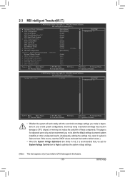
... System Voltage Optimized item blinks in system's failure to CPU, chipset, or memory and reduce the useful life of these components. If this feature. - 35 - BIOS Setup Incorrectly doing overclock/overvoltage may result in red, it is dependent on your overall system configurations. 2-3 MB Intelligent Tweaker(M.I.T.) CMOS Setup Utility-Copyright (C) 1984...
... System Voltage Optimized item blinks in system's failure to CPU, chipset, or memory and reduce the useful life of these components. If this feature. - 35 - BIOS Setup Incorrectly doing overclock/overvoltage may result in red, it is dependent on your overall system configurations. 2-3 MB Intelligent Tweaker(M.I.T.) CMOS Setup Utility-Copyright (C) 1984...

Manual
Page 36
... available depends on the CPU being used). Options are : -12%~+12%. After the selection, select Save & Exit Setup in the BIOS Main Menu and then press . Disabled Disables this feature. Value (All Cores) This option is configurable only when Advanced Clock Calibration is... set to All Cores. A message which says "BIOS Is Updating EC Firmware!!! Advanced Clock Calibration Allows you to determine whether to take effect. Manual Allows you to individually enable/disable CPU ...
... available depends on the CPU being used). Options are : -12%~+12%. After the selection, select Save & Exit Setup in the BIOS Main Menu and then press . Disabled Disables this feature. Value (All Cores) This option is configurable only when Advanced Clock Calibration is... set to All Cores. A message which says "BIOS Is Updating EC Firmware!!! Advanced Clock Calibration Allows you to determine whether to take effect. Manual Allows you to individually enable/disable CPU ...
Manual
Page 37
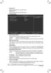
... onboard graphics controller. Options are: Auto (default), 128MB, 256MB, 512MB. This option is configurable only if Init Display First under Advanced BIOS Features is set to PEG and an ATI graphics card is from the D-SUB/DVI-D or D-SUB/HDMI. The adjustable range is installed...display of system memory allocated solely for the onboard graphics controller. D-SUB/HDMI Sets the D-SUB/HDMI as the graphics display. BIOS Setup Auto BIOS automatically determines the primary display port for display. VGA Core Clock control Allows you install a CPU that supports this memory for...
... onboard graphics controller. Options are: Auto (default), 128MB, 256MB, 512MB. This option is configurable only if Init Display First under Advanced BIOS Features is set to PEG and an ATI graphics card is from the D-SUB/DVI-D or D-SUB/HDMI. The adjustable range is installed...display of system memory allocated solely for the onboard graphics controller. D-SUB/HDMI Sets the D-SUB/HDMI as the graphics display. BIOS Setup Auto BIOS automatically determines the primary display port for display. VGA Core Clock control Allows you install a CPU that supports this memory for...


