
Manual
Page 4
Table of Contents Box Contents...6 Optional Items...6 GA-880GM-D2H Motherboard Layout 7 GA-880GM-D2H Motherboard Block Diagram 8 Chapter 1 Hardware Installation 9 1-1 Installation Precautions 9 1-2 Product Specifications 10 1-3 Installing the CPU and CPU Cooler 13 1-3-1 ...Screen 32 2-2 The Main Menu 33 2-3 MB Intelligent Tweaker(M.I.T 35 2-4 Standard CMOS Features 42 2-5 Advanced BIOS Features 44 2-6 Integrated Peripherals 46 2-7 Power Management Setup 49 2-8 PnP/PCI Configurations 51 2-9 PC Health Status 52 2-10 Load Fail-Safe Defaults 54 2-11 Load Optimized Defaults 54 2-12 ...
Table of Contents Box Contents...6 Optional Items...6 GA-880GM-D2H Motherboard Layout 7 GA-880GM-D2H Motherboard Block Diagram 8 Chapter 1 Hardware Installation 9 1-1 Installation Precautions 9 1-2 Product Specifications 10 1-3 Installing the CPU and CPU Cooler 13 1-3-1 ...Screen 32 2-2 The Main Menu 33 2-3 MB Intelligent Tweaker(M.I.T 35 2-4 Standard CMOS Features 42 2-5 Advanced BIOS Features 44 2-6 Integrated Peripherals 46 2-7 Power Management Setup 49 2-8 PnP/PCI Configurations 51 2-9 PC Health Status 52 2-10 Load Fail-Safe Defaults 54 2-11 Load Optimized Defaults 54 2-12 ...

Manual
Page 6
The box contents are for reference only. Box Contents GA-880GM-D2H motherboard Motherboard driver disk User's Manual One IDE cable Two SATA cables I/O Shield • The box contents above are subject to change without notice. • ... on the product package you obtain. Optional Items Floppy disk drive cable (Part No. 12CF1-1FD001-7*R) 2-port USB 2.0 bracket (Part No. 12CR1-1UB030-5*R) 2-port SATA power cable (Part No. 12CF1-2SERPW-0*R) S/PDIF In and Out cable (Part No. 12CR1-1SPINO-1*R) COM port cable (Part No. 12CF1-1CM001-3*R) - 6 -
The box contents are for reference only. Box Contents GA-880GM-D2H motherboard Motherboard driver disk User's Manual One IDE cable Two SATA cables I/O Shield • The box contents above are subject to change without notice. • ... on the product package you obtain. Optional Items Floppy disk drive cable (Part No. 12CF1-1FD001-7*R) 2-port USB 2.0 bracket (Part No. 12CR1-1UB030-5*R) 2-port SATA power cable (Part No. 12CF1-2SERPW-0*R) S/PDIF In and Out cable (Part No. 12CR1-1SPINO-1*R) COM port cable (Part No. 12CF1-1CM001-3*R) - 6 -

Manual
Page 9
...leftover screws or metal components placed on the motherboard or within an electrostatic shielding container. • Before unplugging the power supply cable from the power outlet before installing or removing the motherboard or other hardware components. • When connecting hardware components to the ...you do not have an ESD wrist strap, keep your dealer. These stickers are required for warranty validation. • Always remove the AC power by your hands dry and first touch a metal object to eliminate static electricity. • Prior to installing the motherboard, please have a ...
...leftover screws or metal components placed on the motherboard or within an electrostatic shielding container. • Before unplugging the power supply cable from the power outlet before installing or removing the motherboard or other hardware components. • When connecting hardware components to the ...you do not have an ESD wrist strap, keep your dealer. These stickers are required for warranty validation. • Always remove the AC power by your hands dry and first touch a metal object to eliminate static electricity. • Prior to installing the motherboard, please have a ...

Manual
Page 11
Internal Connectors Back Panel Connectors w 1 x 24-pin ATX main power connector w 1 x 4-pin ATX 12V power connector w 1 x floppy disk drive connector w 1 x IDE connector w 4 x SATA 3Gb/s connectors w 1 x CPU fan header w 1 x system fan header w 1 x front panel header w 1 x front panel audio header w 1 x CD In ...
Internal Connectors Back Panel Connectors w 1 x 24-pin ATX main power connector w 1 x 4-pin ATX 12V power connector w 1 x floppy disk drive connector w 1 x IDE connector w 4 x SATA 3Gb/s connectors w 1 x CPU fan header w 1 x system fan header w 1 x front panel header w 1 x front panel audio header w 1 x CD In ...

Manual
Page 13
... triangle) of the CPU. • Do not turn off the computer and unplug the power cord from the power outlet before you begin to install the CPU: • Make sure that the motherboard supports the CPU. (Go to GIGABYTE's website for the latest CPU support list.) • Always turn on the computer if...
... triangle) of the CPU. • Do not turn off the computer and unplug the power cord from the power outlet before you begin to install the CPU: • Make sure that the motherboard supports the CPU. (Go to GIGABYTE's website for the latest CPU support list.) • Always turn on the computer if...

Manual
Page 14
... correctly install the CPU into the motherboard CPU socket. • Before installing the CPU, make sure to turn off the computer and unplug the power cord from the power outlet to prevent damage to the CPU. • Do not force the CPU into their holes. Step 2: Align the CPU pin one finger...
... correctly install the CPU into the motherboard CPU socket. • Before installing the CPU, make sure to turn off the computer and unplug the power cord from the power outlet to prevent damage to the CPU. • Do not force the CPU into their holes. Step 2: Align the CPU pin one finger...

Manual
Page 15
... frame. 1-3-2 Installing the CPU Cooler Follow the steps below to correctly install the CPU cooler on the CPU. (The following procedure uses the GIGABYTE cooler as the picture above shows) to lock into place. (Refer to your CPU cooler installation manual for instructions on installing the cooler.) Step... 5: Finally, attach the power connector of the CPU cooler to the CPU fan header (CPU_FAN) on the motherboard. Hardware Installation Step 2: Place the CPU cooler on the CPU...
... frame. 1-3-2 Installing the CPU Cooler Follow the steps below to correctly install the CPU cooler on the CPU. (The following procedure uses the GIGABYTE cooler as the picture above shows) to lock into place. (Refer to your CPU cooler installation manual for instructions on installing the cooler.) Step... 5: Finally, attach the power connector of the CPU cooler to the CPU fan header (CPU_FAN) on the motherboard. Hardware Installation Step 2: Place the CPU cooler on the CPU...

Manual
Page 16
... that memory of the same capacity, brand, speed, and chips be used . (Go to GIGABYTE's website for the latest supported memory speeds and memory modules.) • Always turn off the computer and unplug the power cord from the power outlet before installing the memory to CPU limitation, read the following guidelines before you...
... that memory of the same capacity, brand, speed, and chips be used . (Go to GIGABYTE's website for the latest supported memory speeds and memory modules.) • Always turn off the computer and unplug the power cord from the power outlet before installing the memory to CPU limitation, read the following guidelines before you...

Manual
Page 17
... memory socket. As indicated in one direction. 1-4-2 Installing a Memory Before installing a memory module, make sure to turn off the computer and unplug the power cord from the power outlet to prevent damage to install DDR3 DIMMs on this motherboard. Step 1: Note the orientation of the memory socket. Step 2: The clips at both...
... memory socket. As indicated in one direction. 1-4-2 Installing a Memory Before installing a memory module, make sure to turn off the computer and unplug the power cord from the power outlet to prevent damage to install DDR3 DIMMs on this motherboard. Step 1: Note the orientation of the memory socket. Step 2: The clips at both...
Manual
Page 18
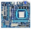
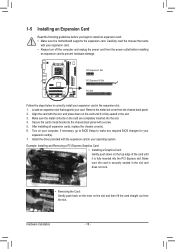
... the driver provided with your card. Carefully read the manual that supports your expansion card. • Always turn off the computer and unplug the power cord from the power outlet before you begin to install an expansion card: • Make sure the motherboard supports the expansion card. PCI Express x1 Slot PCI...
... the driver provided with your card. Carefully read the manual that supports your expansion card. • Always turn off the computer and unplug the power cord from the power outlet before you begin to install an expansion card: • Make sure the motherboard supports the expansion card. PCI Express x1 Slot PCI...

Manual
Page 21
... with the connectors you wish to connect. • Before installing the devices, be sure to the connector on the motherboard. - 21 - Unplug the power cord from the power outlet to prevent damage to the devices. • After installing the device and before connecting external devices: • First make sure the device cable...
... with the connectors you wish to connect. • Before installing the devices, be sure to the connector on the motherboard. - 21 - Unplug the power cord from the power outlet to prevent damage to the devices. • After installing the device and before connecting external devices: • First make sure the device cable...

Manual
Page 22
...on the motherboard. The 12V power connector mainly supplies power to the power connector in the correct orientation. If a power supply is recommended that a power supply that can withstand high power consumption be used that does not provide the required power, the result can supply enough stable power to all devices are properly ...Pin No. 1 2 3 4 5 6 7 8 9 10 11 12 Definition Pin No. 3.3V 13 3.3V 14 GND 15 +5V 16 GND 17 +5V 18 GND 19 Power Good 20 5VSB (stand by +5V) 21 +12V 22 +12V (Only for 2x12-pin ATX) 23 3.3V (Only for 2x12-pin ATX) 24 Definition 3.3V...
...on the motherboard. The 12V power connector mainly supplies power to the power connector in the correct orientation. If a power supply is recommended that a power supply that can withstand high power consumption be used that does not provide the required power, the result can supply enough stable power to all devices are properly ...Pin No. 1 2 3 4 5 6 7 8 9 10 11 12 Definition Pin No. 3.3V 13 3.3V 14 GND 15 +5V 16 GND 17 +5V 18 GND 19 Power Good 20 5VSB (stand by +5V) 21 +12V 22 +12V (Only for 2x12-pin ATX) 23 3.3V (Only for 2x12-pin ATX) 24 Definition 3.3V...

Manual
Page 25
... wire assignments and the pin assignments are matched correctly. - 25 - The front panel design may configure the way to turn off (S5). • PW (Power Switch, Red): Connects to the speaker on the chassis front panel. Hardware Installation PW+ PWSPEAK+ SPEAK- 2 20 1 19 HD+ HD- You may differ ... information about beep codes. • HD (Hard Drive Activity LED, Blue) Connects to the hard drive activity LED on the chassis to the power status indicator on the chassis front panel. The LED is on when the hard drive is operating. One single short beep will be heard if...
... wire assignments and the pin assignments are matched correctly. - 25 - The front panel design may configure the way to turn off (S5). • PW (Power Switch, Red): Connects to the speaker on the chassis front panel. Hardware Installation PW+ PWSPEAK+ SPEAK- 2 20 1 19 HD+ HD- You may differ ... information about beep codes. • HD (Hard Drive Activity LED, Blue) Connects to the hard drive activity LED on the chassis to the power status indicator on the chassis front panel. The LED is on when the hard drive is operating. One single short beep will be heard if...

Manual
Page 26
Definition 1 MIC 2 GND 1 9 3 MIC2_R 2 GND 3 MIC Power 4 -ACZ_DET 4 NC 5 LINE2_R 5 Line Out (R) 6 GND 6 NC 7 FAUDIO_JD 7 NC 8 No Pin 8 No Pin 9 LINE2_L 9 Line Out (L) 10 GND 10 NC • The front panel audio ...
Definition 1 MIC 2 GND 1 9 3 MIC2_R 2 GND 3 MIC Power 4 -ACZ_DET 4 NC 5 LINE2_R 5 Line Out (R) 6 GND 6 NC 7 FAUDIO_JD 7 NC 8 No Pin 8 No Pin 9 LINE2_L 9 Line Out (L) 10 GND 10 NC • The front panel audio ...

Manual
Page 27
...pin) cable into the USB header. • Prior to installing the USB bracket, be sure to turn off your computer and unplug the power cord from the power outlet to prevent damage to USB 2.0/1.1 specification. 11) SPDIF_IO (S/PDIF In/Out Header) This header supports digital S/PDIF In/Out. Each... digital audio in. For purchasing the optional S/PDIF In and Out cable, please contact the local dealer. 6 5 2 1 Pin No. 1 2 3 G.QBOF4M 5 6 Definition Power No Pin SPDIF SPDIFI GND GND 12) F_USB1/F_USB2 (USB Headers) The headers conform to the USB bracket. - 27 - Pin No. Via an optional S/PDIF...
...pin) cable into the USB header. • Prior to installing the USB bracket, be sure to turn off your computer and unplug the power cord from the power outlet to prevent damage to USB 2.0/1.1 specification. 11) SPDIF_IO (S/PDIF In/Out Header) This header supports digital S/PDIF In/Out. Each... digital audio in. For purchasing the optional S/PDIF In and Out cable, please contact the local dealer. 6 5 2 1 Pin No. 1 2 3 G.QBOF4M 5 6 Definition Power No Pin SPDIF SPDIFI GND GND 12) F_USB1/F_USB2 (USB Headers) The headers conform to the USB bracket. - 27 - Pin No. Via an optional S/PDIF...

Manual
Page 28
... 2, "BIOS Setup," for a few seconds. Hardware Installation - 28 - Open: Normal Short: Clear CMOS Values • Always turn off your computer and unplug the power cord from the power outlet before clearing the CMOS values. • After clearing the CMOS values and before turning on the two pins to temporarily short the two...
... 2, "BIOS Setup," for a few seconds. Hardware Installation - 28 - Open: Normal Short: Clear CMOS Values • Always turn off your computer and unplug the power cord from the power outlet before clearing the CMOS values. • After clearing the CMOS values and before turning on the two pins to temporarily short the two...

Manual
Page 29
...remove the battery from the battery holder and wait for 5 seconds.) 3. Turn off your computer and unplug the power cord. 2. 15) BAT(Battery) The battery provides power to keep the values (such as BIOS configurations, date, and time information) in the CMOS when the computer is... side should face up). • Used batteries must be lost. Replace the battery. 4. Plug in the power cord and restart your computer. • Always turn off your computer and unplug the power cord before replacing the battery. • Replace the battery with local environmental regulations. - 29 -
...remove the battery from the battery holder and wait for 5 seconds.) 3. Turn off your computer and unplug the power cord. 2. 15) BAT(Battery) The battery provides power to keep the values (such as BIOS configurations, date, and time information) in the CMOS when the computer is... side should face up). • Used batteries must be lost. Replace the battery. 4. Plug in the power cord and restart your computer. • Always turn off your computer and unplug the power cord before replacing the battery. • Replace the battery with local environmental regulations. - 29 -

Manual
Page 31
...turned off, the battery on the motherboard supplies the necessary power to the CMOS to keep the configuration values in the CMOS on using the current version of BIOS, it with caution. To upgrade the BIOS, use either the GIGABYTE Q-Flash or @BIOS utility. • Q-Flash allows the...8226; BIOS will emit a beep code during system startup, saving system parameters and loading operating system, etc. Its major functions include conducting the Power-On Self-Test (POST) during the POST. BIOS includes a BIOS Setup program that searches and downloads the latest version of BIOS from the Internet...
...turned off, the battery on the motherboard supplies the necessary power to the CMOS to keep the configuration values in the CMOS on using the current version of BIOS, it with caution. To upgrade the BIOS, use either the GIGABYTE Q-Flash or @BIOS utility. • Q-Flash allows the...8226; BIOS will emit a beep code during system startup, saving system parameters and loading operating system, etc. Its major functions include conducting the Power-On Self-Test (POST) during the POST. BIOS includes a BIOS Setup program that searches and downloads the latest version of BIOS from the Internet...

Manual
Page 33
...: E2) CMOS Setup Utility-Copyright (C) 1984-2010 Award Software MB Intelligent Tweaker(M.I.T.) Standard CMOS Features Advanced BIOS Features Integrated Peripherals Power Management Setup PnP/PCI Configurations PC Health Status Load Fail-Safe Defaults Load Optimized Defaults Set Supervisor Password Set User Password Save & Exit...
...: E2) CMOS Setup Utility-Copyright (C) 1984-2010 Award Software MB Intelligent Tweaker(M.I.T.) Standard CMOS Features Advanced BIOS Features Integrated Peripherals Power Management Setup PnP/PCI Configurations PC Health Status Load Fail-Safe Defaults Load Optimized Defaults Set Supervisor Password Set User Password Save & Exit...
Manual
Page 34
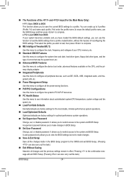
...; Integrated Peripherals Use this menu to configure all peripheral devices, such as IDE, SATA, USB, integrated audio, and integrated LAN, etc. Power Management Setup Use this menu to configure all the changes made in the BIOS Setup program to the CMOS and exit BIOS Setup. (Pressing can...also carry out this task.) BIOS Setup - 34 - A user password only allows you to make changes. Save & Exit Setup Save all the power-saving functions. PnP/PCI Configurations Use this menu to configure the system's PCI & PnP resources. PC Health Status Use this menu to ...
...; Integrated Peripherals Use this menu to configure all peripheral devices, such as IDE, SATA, USB, integrated audio, and integrated LAN, etc. Power Management Setup Use this menu to configure all the changes made in the BIOS Setup program to the CMOS and exit BIOS Setup. (Pressing can...also carry out this task.) BIOS Setup - 34 - A user password only allows you to make changes. Save & Exit Setup Save all the power-saving functions. PnP/PCI Configurations Use this menu to configure the system's PCI & PnP resources. PC Health Status Use this menu to ...


