
Manual
Page 1
GA-880G-UD3H AM3 socket motherboard for AMD Phenom™ II processor/AMD Athlon™ II processor User's Manual Rev. 1401
GA-880G-UD3H AM3 socket motherboard for AMD Phenom™ II processor/AMD Athlon™ II processor User's Manual Rev. 1401

Manual
Page 2
Motherboard GA-880G-UD3H Aug. 27, 2010 Motherboard GA-880G-UD3H Aug. 27, 2010
Motherboard GA-880G-UD3H Aug. 27, 2010 Motherboard GA-880G-UD3H Aug. 27, 2010

Manual
Page 3
... laws and is the property of the motherboard is 1.0. For product-related information, check on our website at: http://www.gigabyte.com Identifying Your Motherboard Revision The revision number on your motherboard revision before updating motherboard BIOS, drivers, or when looking for...Quick Installation Guide included with the product. Example: The trademarks mentioned in the use GIGABYTE's unique features, read or download the information on/from the Support&Downloads\Motherboard\Technology Guide page on how to their respective owners. For instructions on our website...
... laws and is the property of the motherboard is 1.0. For product-related information, check on our website at: http://www.gigabyte.com Identifying Your Motherboard Revision The revision number on your motherboard revision before updating motherboard BIOS, drivers, or when looking for...Quick Installation Guide included with the product. Example: The trademarks mentioned in the use GIGABYTE's unique features, read or download the information on/from the Support&Downloads\Motherboard\Technology Guide page on how to their respective owners. For instructions on our website...

Manual
Page 4
Table of Contents Box Contents...6 Optional Items...6 GA-880G-UD3H Motherboard Layout 7 GA-880G-UD3H Motherboard Block Diagram 8 Chapter 1 Hardware Installation 9 1-1 Installation Precautions 9 1-2 Product Specifications 10 1-3 Installing the CPU and CPU Cooler 13 1-3-1 Installing the CPU 13 1-3-2 Installing the CPU Cooler ...
Table of Contents Box Contents...6 Optional Items...6 GA-880G-UD3H Motherboard Layout 7 GA-880G-UD3H Motherboard Block Diagram 8 Chapter 1 Hardware Installation 9 1-1 Installation Precautions 9 1-2 Product Specifications 10 1-3 Installing the CPU and CPU Cooler 13 1-3-1 Installing the CPU 13 1-3-2 Installing the CPU Cooler ...

Manual
Page 6
The box contents are for reference only. Box Contents GA-880G-UD3H motherboard Motherboard driver disk User's Manual Quick Installation Guide One IDE cable Two SATA cables I/O Shield • The box contents above are subject to change without notice. • The motherboard image is for reference only and the actual items shall depend on the product package...
The box contents are for reference only. Box Contents GA-880G-UD3H motherboard Motherboard driver disk User's Manual Quick Installation Guide One IDE cable Two SATA cables I/O Shield • The box contents above are subject to change without notice. • The motherboard image is for reference only and the actual items shall depend on the product package...

Manual
Page 7
When the PCIEX4_1 slot is populated with the PCIEX4_1 slot. GA-880G-UD3H Motherboard Layout KB_USB VGA_DVI ATX_12V_2X4 HDMI OPTICAL USB_1394 USB_LAN CPU_FAN Socket AM3 PWR_FAN ATX AUDIO F_AUDIO PCIEX1_1 AMD 880G iTE IT8718 F_USB1 F_USB2 F_USB3 DDR3_1 DDR3_2 DDR3_3 DDR3_4 Realtek RTL8111D/E SYS_FAN2 PCIEX16_1 CD_IN PCIEX1_2 (Note) GA-880G-UD3H PCIEX1_3 (Note) CODEC PCIEX4_1 (Note) SPDIF_IO BAT CLR_CMOS...
When the PCIEX4_1 slot is populated with the PCIEX4_1 slot. GA-880G-UD3H Motherboard Layout KB_USB VGA_DVI ATX_12V_2X4 HDMI OPTICAL USB_1394 USB_LAN CPU_FAN Socket AM3 PWR_FAN ATX AUDIO F_AUDIO PCIEX1_1 AMD 880G iTE IT8718 F_USB1 F_USB2 F_USB3 DDR3_1 DDR3_2 DDR3_3 DDR3_4 Realtek RTL8111D/E SYS_FAN2 PCIEX16_1 CD_IN PCIEX1_2 (Note) GA-880G-UD3H PCIEX1_3 (Note) CODEC PCIEX4_1 (Note) SPDIF_IO BAT CLR_CMOS...

Manual
Page 8
.... The PCIEX1_2 and PCIEX1_3 slots share bandwidth with a x4 card, the PCIEX1_2 and PCIEX1_3 slots become unavailable. - 8 - TSB43AB23 3 IEEE 1394a AMD 880G D-Sub DVI-D (Note 2) HDMI (Note 2) 12 USB Ports AMD SB710 Dual BIOS CODEC LPC Bus iTE IT8718 Floppy LPT Port COM Port PS/2 ...(Note 2) (Note 3) To reach DDR3 1866 MHz or above, you must install two memory modules and install them in the DDR3_3 and DDR3_4 memory sockets. GA-880G-UD3H Motherboard Block Diagram 1 PCI Express x16 1 PCI Express x4 (Note 3) AM3 CPU CPU CLK+/- (200 MHz) DDR3 1866 (O.C.) (Note 1)/ 1333/1066 MHz ...
.... The PCIEX1_2 and PCIEX1_3 slots share bandwidth with a x4 card, the PCIEX1_2 and PCIEX1_3 slots become unavailable. - 8 - TSB43AB23 3 IEEE 1394a AMD 880G D-Sub DVI-D (Note 2) HDMI (Note 2) 12 USB Ports AMD SB710 Dual BIOS CODEC LPC Bus iTE IT8718 Floppy LPT Port COM Port PS/2 ...(Note 2) (Note 3) To reach DDR3 1866 MHz or above, you must install two memory modules and install them in the DDR3_3 and DDR3_4 memory sockets. GA-880G-UD3H Motherboard Block Diagram 1 PCI Express x16 1 PCI Express x4 (Note 3) AM3 CPU CPU CLK+/- (200 MHz) DDR3 1866 (O.C.) (Note 1)/ 1333/1066 MHz ...

Manual
Page 9
...is best to the use of the product, please consult a certified computer technician. - 9 - Chapter 1 Hardware Installation 1-1 Installation Precautions The motherboard contains numerous delicate electronic circuits and components which can lead to damage to system components as well as physical harm to the user. •... for warranty validation. • Always remove the AC power by your hardware components are connected. • To prevent damage to the motherboard, do not have an ESD wrist strap, keep your hands dry and first touch a metal object to eliminate static electricity. •...
...is best to the use of the product, please consult a certified computer technician. - 9 - Chapter 1 Hardware Installation 1-1 Installation Precautions The motherboard contains numerous delicate electronic circuits and components which can lead to damage to system components as well as physical harm to the user. •... for warranty validation. • Always remove the AC power by your hardware components are connected. • To prevent damage to the motherboard, do not have an ESD wrist strap, keep your hands dry and first touch a metal object to eliminate static electricity. •...

Manual
Page 12
... 4) Simultaneous output for DVI-D and HDMI is supported will depend on the CPU/system cooler you install. (Note 7) Available functions in EasyTune may differ by motherboard model.
... 4) Simultaneous output for DVI-D and HDMI is supported will depend on the CPU/system cooler you install. (Note 7) Available functions in EasyTune may differ by motherboard model.
Manual
Page 13
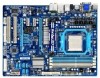
... standard requirements for the latest CPU support list.) • Always turn on the computer if the CPU cooler is not recommended that the motherboard supports the CPU. (Go to GIGABYTE's website for the peripherals. 1-3 Installing the CPU and CPU Cooler Read the following guidelines before you begin to install the CPU: •...
... standard requirements for the latest CPU support list.) • Always turn on the computer if the CPU cooler is not recommended that the motherboard supports the CPU. (Go to GIGABYTE's website for the peripherals. 1-3 Installing the CPU and CPU Cooler Read the following guidelines before you begin to install the CPU: •...

Manual
Page 14
... on the CPU socket and gently insert the CPU into the fully locked position. B. Follow the steps below to correctly install the CPU into the motherboard CPU socket. • Before installing the CPU, make sure to turn off the computer and unplug the power cord from the power outlet to prevent...
... on the CPU socket and gently insert the CPU into the fully locked position. B. Follow the steps below to correctly install the CPU into the motherboard CPU socket. • Before installing the CPU, make sure to turn off the computer and unplug the power cord from the power outlet to prevent...

Manual
Page 15
... cooler.) Step 5: Finally, attach the power connector of the CPU cooler to correctly install the CPU cooler on the CPU. (The following procedure uses the GIGABYTE cooler as the example.) Step 1: Apply an even and thin layer of thermal grease on the surface of the retention frame. Hardware Installation Use extreme.... - 15 - Step 2: Place the CPU cooler on the CPU. 1-3-2 Installing the CPU Cooler Follow the steps below to the CPU fan header (CPU_FAN) on the motherboard.
... cooler.) Step 5: Finally, attach the power connector of the CPU cooler to correctly install the CPU cooler on the CPU. (The following procedure uses the GIGABYTE cooler as the example.) Step 1: Apply an even and thin layer of thermal grease on the surface of the retention frame. Hardware Installation Use extreme.... - 15 - Step 2: Place the CPU cooler on the CPU. 1-3-2 Installing the CPU Cooler Follow the steps below to the CPU fan header (CPU_FAN) on the motherboard.
Manual
Page 16
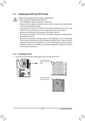
...modules, it is installed. 2. If you begin to insert the memory, switch the direction. 1-4-1 Dual Channel Memory Configuration This motherboard provides four DDR3 memory sockets and supports Dual Channel Technology. The four DDR3 memory sockets are unable to install the memory: •..., speed, and chips be enabled if only one direction. Hardware Installation - 16 - Dual Channel mode cannot be used . (Go to GIGABYTE's website for optimum performance. 1-4 Installing the Memory Read the following : Channel 0: DDR3_1, DDR3_3 Channel 1: DDR3_2, DDR3_4 Dual Channel Memory Configurations...
...modules, it is installed. 2. If you begin to insert the memory, switch the direction. 1-4-1 Dual Channel Memory Configuration This motherboard provides four DDR3 memory sockets and supports Dual Channel Technology. The four DDR3 memory sockets are unable to install the memory: •..., speed, and chips be enabled if only one direction. Hardware Installation - 16 - Dual Channel mode cannot be used . (Go to GIGABYTE's website for optimum performance. 1-4 Installing the Memory Read the following : Channel 0: DDR3_1, DDR3_3 Channel 1: DDR3_2, DDR3_4 Dual Channel Memory Configurations...

Manual
Page 17
..., make sure to turn off the computer and unplug the power cord from the power outlet to prevent damage to install DDR3 DIMMs on this motherboard. Place the memory module on the socket.
..., make sure to turn off the computer and unplug the power cord from the power outlet to prevent damage to install DDR3 DIMMs on this motherboard. Place the memory module on the socket.

Manual
Page 18
... PCI Express x16 Slot (PCIEX16_1) PCI Express x16 Slot (PCIEX4_1) PCI Slot Follow the steps below to install an expansion card: • Make sure the motherboard supports the expansion card. Make sure the metal contacts on your expansion card(s). 7. After installing all expansion cards, replace the chassis cover(s). 6. Example: Installing and...
... PCI Express x16 Slot (PCIEX16_1) PCI Express x16 Slot (PCIEX4_1) PCI Slot Follow the steps below to install an expansion card: • Make sure the motherboard supports the expansion card. Make sure the metal contacts on your expansion card(s). 7. After installing all expansion cards, replace the chassis cover(s). 6. Example: Installing and...

Manual
Page 19
...Center. D. Read the following items under the Advanced BIOS Features menu: - An ATI Hybrid CrossFireX-supported motherboard and correct driver - Configuring the Graphics Driver After installing the motherboard driver in the operating system first. - 19 - Windows 7/Vista operating system - Connecting the Graphics Cards ...the Enable CrossFire™ check box is selected. (Note 1) You do not have to install the graphics card driver if the motherboard chipset driver has been installed. (Note 2) To change the Internal Graphics Mode or UMA Frame Buffer Size setting in "1-5 Installing...
...Center. D. Read the following items under the Advanced BIOS Features menu: - An ATI Hybrid CrossFireX-supported motherboard and correct driver - Configuring the Graphics Driver After installing the motherboard driver in the operating system first. - 19 - Windows 7/Vista operating system - Connecting the Graphics Cards ...the Enable CrossFire™ check box is selected. (Note 1) You do not have to install the graphics card driver if the motherboard chipset driver has been installed. (Note 2) To change the Internal Graphics Mode or UMA Frame Buffer Size setting in "1-5 Installing...
Manual
Page 21
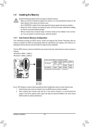
Dual Display Configurations: This motherboard provides three ports for an IEEE 1394a device. vanced BIOS Features," for more information) • Playback software: CyberLink PowerDVD 8.0 or later (Note: Please ensure Hardware ... HDMI + D-Sub Supported or Not Yes No Yes B. Use this feature, ensure that supports digital optical audio. Do not rock it straight out from the motherboard. • When removing the cable, pull it side to side to Chapter 2, "BIOS Setup," "Ad- Playback of HD DVD and Blu-ray Discs: In order...
Dual Display Configurations: This motherboard provides three ports for an IEEE 1394a device. vanced BIOS Features," for more information) • Playback software: CyberLink PowerDVD 8.0 or later (Note: Please ensure Hardware ... HDMI + D-Sub Supported or Not Yes No Yes B. Use this feature, ensure that supports digital optical audio. Do not rock it straight out from the motherboard. • When removing the cable, pull it side to side to Chapter 2, "BIOS Setup," "Ad- Playback of HD DVD and Blu-ray Discs: In order...

Manual
Page 23
..., make sure your devices are compliant with the connectors you wish to connect. • Before installing the devices, be sure to the connector on the motherboard. - 23 - Hardware Installation Unplug the power cord from the power outlet to prevent damage to the devices. • After installing the device and before connecting...
..., make sure your devices are compliant with the connectors you wish to connect. • Before installing the devices, be sure to the connector on the motherboard. - 23 - Hardware Installation Unplug the power cord from the power outlet to prevent damage to the devices. • After installing the device and before connecting...

Manual
Page 24
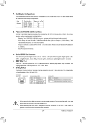
... be used (500W or greater). Connect the power supply cable to the CPU. If a power supply is turned off and all the components on the motherboard. 1/2) ATX_12V_2X4/ATX (2x4 12V Power Connector and 2x12 Main Power Connector) With the use of the power connector, the power supply can supply enough stable...
... be used (500W or greater). Connect the power supply cable to the CPU. If a power supply is turned off and all the components on the motherboard. 1/2) ATX_12V_2X4/ATX (2x4 12V Power Connector and 2x12 Main Power Connector) With the use of the power connector, the power supply can supply enough stable...

Manual
Page 25
The motherboard supports CPU fan speed control, which requires the use of floppy disk drives supported are not configuration jumper blocks. Definition 1 CPU_FAN 1 GND 2 +12V / Speed Control 3 ... control design. For purchasing the optional floppy disk drive cable, please contact the local dealer. 33 1 34 2 - 25 - 3/4/5) CPU_FAN/SYS_FAN1/SYS_FAN2/PWR_FAN (Fan Headers) The motherboard has a 4-pin CPU fan header (CPU_FAN), a 3-pin (SYS_FAN2) and a 4-pin (SYS_ FAN1) system fan headers, and a 3-pin power fan header (PWR_FAN). Hardware Installation Overheating may...
The motherboard supports CPU fan speed control, which requires the use of floppy disk drives supported are not configuration jumper blocks. Definition 1 CPU_FAN 1 GND 2 +12V / Speed Control 3 ... control design. For purchasing the optional floppy disk drive cable, please contact the local dealer. 33 1 34 2 - 25 - 3/4/5) CPU_FAN/SYS_FAN1/SYS_FAN2/PWR_FAN (Fan Headers) The motherboard has a 4-pin CPU fan header (CPU_FAN), a 3-pin (SYS_FAN2) and a 4-pin (SYS_ FAN1) system fan headers, and a 3-pin power fan header (PWR_FAN). Hardware Installation Overheating may...


