Manual
Page 2
... 3 Using the Web UI...4 Gigabyte Content Management System Console Overview 5 Enter Gigabyte Content Management System Console 6 Properties ...6 Configuration ...7 Network ...7 Network Security ...8 Users ...9 Services ...10 IPMI ...11 Time Setting ...13 Sessions ...14 LDAP ...15 Updates ...16 Utilities ...17 Server Information ...18 Power Control ...18 Voltages ...19 Thermal ...20 Fans ...20 Temperature ...21 System Event Log ...22 Event Management ...23 Platform Event ...23 Trap Settings ...24 Email Settings ...25 Serial Over LAN ...26...
... 3 Using the Web UI...4 Gigabyte Content Management System Console Overview 5 Enter Gigabyte Content Management System Console 6 Properties ...6 Configuration ...7 Network ...7 Network Security ...8 Users ...9 Services ...10 IPMI ...11 Time Setting ...13 Sessions ...14 LDAP ...15 Updates ...16 Utilities ...17 Server Information ...18 Power Control ...18 Voltages ...19 Thermal ...20 Fans ...20 Temperature ...21 System Event Log ...22 Event Management ...23 Platform Event ...23 Trap Settings ...24 Email Settings ...25 Serial Over LAN ...26...
Manual
Page 4
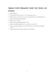
... LAN. FRU information report includes main board part number, product name, and manufacturer, etc.) Health status/Hardware monitoring report. Events log, view, and clear. Event notification via PET (Platform Event Trap). Platform Event Filtering (PEF) to take selected action for selected events. Chassis management includes power control and status report, front panel buttons and LEDs control. Support...
... LAN. FRU information report includes main board part number, product name, and manufacturer, etc.) Health status/Hardware monitoring report. Events log, view, and clear. Event notification via PET (Platform Event Trap). Platform Event Filtering (PEF) to take selected action for selected events. Chassis management includes power control and status report, front panel buttons and LEDs control. Support...

Manual
Page 5
The web server shall support 4 concurrent connections Web-based GUI is supported on the following browsers: Microsoft Windows: • Internet Explorer 6 and 7 • Mozilla® Firefox® 2.0 or later Linux: Mozilla Firefox 2.0 or later 4 Using the Web UI The BMC firmware features an embedded web server, enabling users to connect to the BMC using an Internet browser (Microsoft® Internet Explorer™).
The web server shall support 4 concurrent connections Web-based GUI is supported on the following browsers: Microsoft Windows: • Internet Explorer 6 and 7 • Mozilla® Firefox® 2.0 or later Linux: Mozilla Firefox 2.0 or later 4 Using the Web UI The BMC firmware features an embedded web server, enabling users to connect to the BMC using an Internet browser (Microsoft® Internet Explorer™).
Manual
Page 6
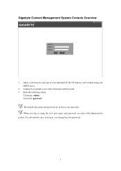
The IP address can be found using the root user name and password, you have full administrative powers. It is advised that once you change the root password. 5 Gigabyte Content Management System Console Overview 1. Open a web browser and type in , you log in your DHCP server. 2. Enter the following values: Username: admin Password: password The default user name and password are in using your identified IP. When you to enter Username and Password. 3. A dialog box prompts you log in lower-case characters.
The IP address can be found using the root user name and password, you have full administrative powers. It is advised that once you change the root password. 5 Gigabyte Content Management System Console Overview 1. Open a web browser and type in , you log in your DHCP server. 2. Enter the following values: Username: admin Password: password The default user name and password are in using your identified IP. When you to enter Username and Password. 3. A dialog box prompts you log in lower-case characters.

Manual
Page 8
... related settings through the NIC2 port. (Shared NIC Mode) Failover Mode When set to take effect of changes. 7 Dedicate Mode When set to Failover Mode, you can configure the BMC related settings through the BMC or NIC2 port. (Backup Mode) When you finish configuration, click Apply Change. Shared Mode When set to Shared Mode, you can view and modify the network settings on this screen. Select the Network Mode from the drop-down list.
... related settings through the NIC2 port. (Shared NIC Mode) Failover Mode When set to take effect of changes. 7 Dedicate Mode When set to Failover Mode, you can configure the BMC related settings through the BMC or NIC2 port. (Backup Mode) When you finish configuration, click Apply Change. Shared Mode When set to Shared Mode, you can view and modify the network settings on this screen. Select the Network Mode from the drop-down list.
Manual
Page 9
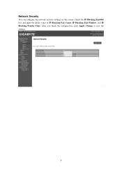
Check the IP Blocking Enabled box and input the desire value of IP Blocking Fail Count, IP Blocking Fail Window, and IP Blocking Penalty Time. After you finish the configuration, click Apply Change to save the settings. 8 Network Security You can configure the network security settings on this screen.
Check the IP Blocking Enabled box and input the desire value of IP Blocking Fail Count, IP Blocking Fail Window, and IP Blocking Penalty Time. After you finish the configuration, click Apply Change to save the settings. 8 Network Security You can configure the network security settings on this screen.

Manual
Page 10
Users To configure a specific user, click the Users ID. NOTE: BMC convention for User ID 1 with a null username (all zero's) and a null password (all zero's). To display new user information, click Refresh. Applications may then present this to configure the entry for enabling an 'anonymous' login is to the user as an anonymous login. 9
Users To configure a specific user, click the Users ID. NOTE: BMC convention for User ID 1 with a null username (all zero's) and a null password (all zero's). To display new user information, click Refresh. Applications may then present this to configure the entry for enabling an 'anonymous' login is to the user as an anonymous login. 9
Manual
Page 11
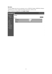
By default, the timeout is 1800 seconds. When you finish the configuration, click Apply Changes. 10 Services You can configure the web server parameters (such as, HTTP Port Number, HTTPS Port Number, and Timeout) on a remote computer.
By default, the timeout is 1800 seconds. When you finish the configuration, click Apply Changes. 10 Services You can configure the web server parameters (such as, HTTP Port Number, HTTPS Port Number, and Timeout) on a remote computer.
Manual
Page 12
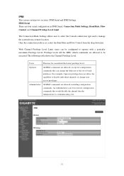
... An Administrator can change user access privileges. Administrator All BMC commands are four serial configuration in IPMI Serial: Connection Mode Settings, Baud Rate, Flow Control, and Channel Privilege Level Limit. IPMI This screen contains two sections: IPMI Serial and IPMI Settings. Privilege levels tell the BMC which commands are allowed, except for configuration commands that can even execute configuration commands that would disable the channel that the Administrator...
... An Administrator can change user access privileges. Administrator All BMC commands are four serial configuration in IPMI Serial: Connection Mode Settings, Baud Rate, Flow Control, and Channel Privilege Level Limit. IPMI This screen contains two sections: IPMI Serial and IPMI Settings. Privilege levels tell the BMC which commands are allowed, except for configuration commands that can even execute configuration commands that would disable the channel that the Administrator...

Manual
Page 13
When you finish the configuration, click "Apply Changes". 12 To activate IPMI remote configuration by LAN, check Enable IPMI Over LAN option, define the Channel Privilege Level Limit, and enter the Encryption Key. IPMI Settings IPMI Settings provides remote configuration over LAN.
When you finish the configuration, click "Apply Changes". 12 To activate IPMI remote configuration by LAN, check Enable IPMI Over LAN option, define the Channel Privilege Level Limit, and enter the Encryption Key. IPMI Settings IPMI Settings provides remote configuration over LAN.
Manual
Page 14
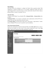
... button. Select Slew mode when you want to configure the Network Time acquisition method. Time Synchronization Method Specifies the synchronization method for Requested Mode. You can modify configuration settings and click the Apply Changes button to execute the settings, as well as click the Sync Time Now button (when in Requested Mode) to request an immediate clock set Requested Mode, or Daemon Mode in place. Time Setting...
... button. Select Slew mode when you want to configure the Network Time acquisition method. Time Synchronization Method Specifies the synchronization method for Requested Mode. You can modify configuration settings and click the Apply Changes button to execute the settings, as well as click the Sync Time Now button (when in Requested Mode) to request an immediate clock set Requested Mode, or Daemon Mode in place. Time Setting...
Manual
Page 16
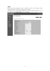
Click Apply Changes to access the LDAP server. Check the box below to enable LDAP authentication and enter the required information to save your changes. 15 LDAP LDAP screen allows download user list of LDAP server then create Gigabyte Content Management System Console user account from this list directly.
Click Apply Changes to access the LDAP server. Check the box below to enable LDAP authentication and enter the required information to save your changes. 15 LDAP LDAP screen allows download user list of LDAP server then create Gigabyte Content Management System Console user account from this list directly.

Manual
Page 17
Select the file on your local system using Browse. Updates The firmware can be updated remotely. Click Upload to update to the new version of firmware. 16 To update firmware, follow the instruction below: 1. Select Update Type. 2.
Select the file on your local system using Browse. Updates The firmware can be updated remotely. Click Upload to update to the new version of firmware. 16 To update firmware, follow the instruction below: 1. Select Update Type. 2.

Manual
Page 19
Additionally you to power on/off/cycle the remote host system. To perform the power control operation, select the operation and click Apply Changes. 18 Server Information Power Control The Power Control allows you can see the remote power status.
Additionally you to power on/off/cycle the remote host system. To perform the power control operation, select the operation and click Apply Changes. 18 Server Information Power Control The Power Control allows you can see the remote power status.

Manual
Page 21
The green color indicates the device is healthy and there's no sensor that has a critical alert. Thermal This screen displays the Fans and Temperatures sensors of a remote host system. Fans 20 The yellow color indicates the device has at least one sensor that has a warning alert. The red color indicates the device has at least one sensor that has any alert. Click Refresh to update current health status for both Fans and Temperatures.
The green color indicates the device is healthy and there's no sensor that has a critical alert. Thermal This screen displays the Fans and Temperatures sensors of a remote host system. Fans 20 The yellow color indicates the device has at least one sensor that has a warning alert. The red color indicates the device has at least one sensor that has any alert. Click Refresh to update current health status for both Fans and Temperatures.
Manual
Page 24
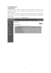
You can trigger an action and generate an alert when a critical hardware-related event occurs. In the Platform Events screen, you can enable the generation of platform event alerts globally by clicking Global Alerting Enable. For each PEF, you can choose the action to generate and send an alert when a platform event occurs. When you finish the configuration, click Apply Changes. 23 Event Management Platform Event A platform event filter (PEF) can also choose to be taken when a platform event occurs.
You can trigger an action and generate an alert when a critical hardware-related event occurs. In the Platform Events screen, you can enable the generation of platform event alerts globally by clicking Global Alerting Enable. For each PEF, you can choose the action to generate and send an alert when a platform event occurs. When you finish the configuration, click Apply Changes. 23 Event Management Platform Event A platform event filter (PEF) can also choose to be taken when a platform event occurs.
Manual
Page 25
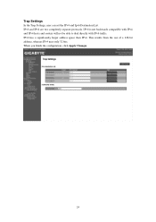
Trap Settings In the Trap Settings, user can set the IPv4 and Ipv6 Destination List. IPv6 and IPv4 are two completely separate protocols. IPv6 has a significantly larger address space than IPv4. When you finish the configuration, click Apply Changes. 24 IPv6 is not backwards compatible with IPv4, and IPv4 hosts and routers will not be able to deal directly with IPv6 traffic. This results from the use of a 128-bit address, whereas IPv4 uses only 32 bits.
Trap Settings In the Trap Settings, user can set the IPv4 and Ipv6 Destination List. IPv6 and IPv4 are two completely separate protocols. IPv6 has a significantly larger address space than IPv4. When you finish the configuration, click Apply Changes. 24 IPv6 is not backwards compatible with IPv4, and IPv4 hosts and routers will not be able to deal directly with IPv6 traffic. This results from the use of a 128-bit address, whereas IPv4 uses only 32 bits.
Manual
Page 26
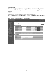
When you can configure to specify the e-mail address, subject and message in the Email Settings. select the STARTTLS Mode and SASL Mode from the drop-down list. SMTP Set E-mail (SMTP) server IP address for sending alert notification to save the settings. Check the SMTP Authentication Enabled box and enter the SMTP IP address, User Name, Password; Email Settings If you want the alert to be sent by email, you finish the configuration, click "Apply Changes". 25 After you finish the configuration, click Apply Change to user.
When you can configure to specify the e-mail address, subject and message in the Email Settings. select the STARTTLS Mode and SASL Mode from the drop-down list. SMTP Set E-mail (SMTP) server IP address for sending alert notification to save the settings. Check the SMTP Authentication Enabled box and enter the SMTP IP address, User Name, Password; Email Settings If you want the alert to be sent by email, you finish the configuration, click "Apply Changes". 25 After you finish the configuration, click Apply Change to user.
Manual
Page 27
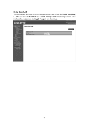
After you finish the configuration, click Apply Change to save the settings. 26 Serial Over LAN You can configure the Serial Over LAN settings on this screen. Check the Enable Serial Over LAN box and select the Baud Rate and Channel Privilege Limit from the drop-down list.
After you finish the configuration, click Apply Change to save the settings. 26 Serial Over LAN You can configure the Serial Over LAN settings on this screen. Check the Enable Serial Over LAN box and select the Baud Rate and Channel Privilege Limit from the drop-down list.
Manual
Page 30
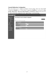
Check the Virtual KVM Configuration Enabled box or Virtual Media Configuration Enabled box, and select the Max Sessions, Remote Port, Video Encryption Enabled, and Preference Client from the drop-down list. After you to save the settings. 29 Console Redirection Configuration This screen allows you finish the configuration, click "Apply Change" to configure the Remote Console settings.
Check the Virtual KVM Configuration Enabled box or Virtual Media Configuration Enabled box, and select the Max Sessions, Remote Port, Video Encryption Enabled, and Preference Client from the drop-down list. After you to save the settings. 29 Console Redirection Configuration This screen allows you finish the configuration, click "Apply Change" to configure the Remote Console settings.


