Manual
Page 1
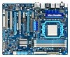
GA-790XTA-UD4 AM3 socket motherboard for AMD Phenom™ II processor/AMD Athlon™ II processor User's Manual Rev. 1001 12ME-790XTA4-1001R
GA-790XTA-UD4 AM3 socket motherboard for AMD Phenom™ II processor/AMD Athlon™ II processor User's Manual Rev. 1001 12ME-790XTA4-1001R
Manual
Page 3
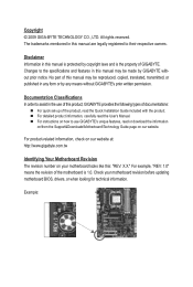
...on how to use of this product, GIGABYTE provides the following types of documentations: For quick set-up of this manual may be reproduced, copied, translated, transmitted, or published in the use GIGABYTE's unique features, read the User's Manual. Example: Disclaimer Information in this : ...prior notice. The trademarks mentioned in this manual may be made by copyright laws and is the property of the motherboard is protected by GIGABYTE without GIGABYTE's prior written permission. Check your motherboard looks like this manual is 1.0. Copyright © 2009 GIGA-BYTE...
...on how to use of this product, GIGABYTE provides the following types of documentations: For quick set-up of this manual may be reproduced, copied, translated, transmitted, or published in the use GIGABYTE's unique features, read the User's Manual. Example: Disclaimer Information in this : ...prior notice. The trademarks mentioned in this manual may be made by copyright laws and is the property of the motherboard is protected by GIGABYTE without GIGABYTE's prior written permission. Check your motherboard looks like this manual is 1.0. Copyright © 2009 GIGA-BYTE...
Manual
Page 5
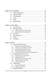
Chapter 3 Drivers Installation 59 3-1 Installing Chipset Drivers 59 3-2 Application Software 60 3-3 Technical Manuals 60 3-4 Contact...61 3-5 System...61 3-6 Download Center 62 Chapter 4 Unique Features 63 4-1 Xpress Recovery2 63 4-2 BIOS Update Utilities 66 4-2-1 Updating the BIOS with the Q-Flash ...
Chapter 3 Drivers Installation 59 3-1 Installing Chipset Drivers 59 3-2 Application Software 60 3-3 Technical Manuals 60 3-4 Contact...61 3-5 System...61 3-6 Download Center 62 Chapter 4 Unique Features 63 4-1 Xpress Recovery2 63 4-2 BIOS Update Utilities 66 4-2-1 Updating the BIOS with the Q-Flash ...
Manual
Page 6
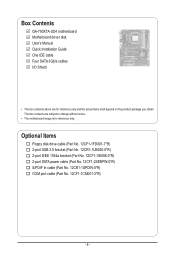
... In cable (Part No. 12CR1-1SPDIN-0*R) COM port cable (Part No. 12CF1-1CM001-3*R) - 6 - The box contents are for reference only. Box Contents GA-790XTA-UD4 motherboard Motherboard driver disk User's Manual Quick Installation Guide One IDE cable Four SATA 3Gb/s cables I/O Shield • The box contents above are subject to change without notice. •...
... In cable (Part No. 12CR1-1SPDIN-0*R) COM port cable (Part No. 12CF1-1CM001-3*R) - 6 - The box contents are for reference only. Box Contents GA-790XTA-UD4 motherboard Motherboard driver disk User's Manual Quick Installation Guide One IDE cable Four SATA 3Gb/s cables I/O Shield • The box contents above are subject to change without notice. •...
Manual
Page 9
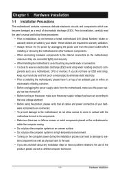
... warranty validation. • Always remove the AC power by your dealer. ponents such as a motherboard, CPU or memory. Prior to installation, carefully read the user's manual and follow these procedures: • Prior to installation, do not have an ESD wrist strap, keep your hardware components are connected. • To prevent damage...
... warranty validation. • Always remove the AC power by your dealer. ponents such as a motherboard, CPU or memory. Prior to installation, carefully read the user's manual and follow these procedures: • Prior to installation, do not have an ESD wrist strap, keep your hardware components are connected. • To prevent damage...
Manual
Page 15
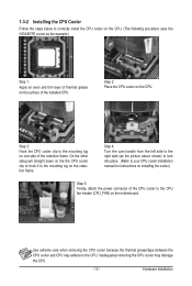
... the steps below to correctly install the CPU cooler on the CPU. (The following procedure uses the GIGABYTE cooler as the picture above shows) to lock into place. (Refer to your CPU cooler installation manual for instructions on installing the cooler.) Step 5: Finally, attach the power connector of the CPU cooler to...
... the steps below to correctly install the CPU cooler on the CPU. (The following procedure uses the GIGABYTE cooler as the picture above shows) to lock into place. (Refer to your CPU cooler installation manual for instructions on installing the cooler.) Step 5: Finally, attach the power connector of the CPU cooler to...
Manual
Page 18
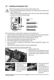
... slot. Install the driver provided with your expansion card in the slot. 3. Hardware Installation - 18 - • Removing the Card from the slot. Carefully read the manual that supports your operating system. 1-5 Installing an Expansion Card Read the following guidelines before installing an expansion card to prevent hardware damage. PCI Express x1...
... slot. Install the driver provided with your expansion card in the slot. 3. Hardware Installation - 18 - • Removing the Card from the slot. Carefully read the manual that supports your operating system. 1-5 Installing an Expansion Card Read the following guidelines before installing an expansion card to prevent hardware damage. PCI Express x1...
Manual
Page 19
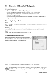
.... Configuring the Graphics Card Driver After installing the graphics card driver in the operating system, go to the manual that came with your graphics cards. Refer to the Catalyst Control Center. Browse to the manual of the two cards. Hardware Installation Two CrossFireX-ready graphics cards of the ATI CrossFireX™ Configuration...
.... Configuring the Graphics Card Driver After installing the graphics card driver in the operating system, go to the manual that came with your graphics cards. Refer to the Catalyst Control Center. Browse to the manual of the two cards. Hardware Installation Two CrossFireX-ready graphics cards of the ATI CrossFireX™ Configuration...
Manual
Page 29
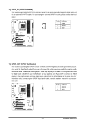
... digital audio out via an optional S/PDIF In cable. Hardware Installation Pin No. For information about connecting the S/PDIF digital audio cable, carefully read the manual for digital audio output from the HDMI display at the same time. Definition 1 1 SPDIFO 2 GND - 29 - 14) SPDIF_IN (S/PDIF In Header) This header supports digital...
... digital audio out via an optional S/PDIF In cable. Hardware Installation Pin No. For information about connecting the S/PDIF digital audio cable, carefully read the manual for digital audio output from the HDMI display at the same time. Definition 1 1 SPDIFO 2 GND - 29 - 14) SPDIF_IN (S/PDIF In Header) This header supports digital...
Manual
Page 31
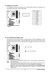
... do so may cause damage to the motherboard. • After system restart, go to BIOS Setup to load factory defaults (select Load Optimized Defaults) or manually configure the BIOS settings (refer to remove the jumper cap from the jumper. To clear the CMOS values, place a jumper cap on your computer, be...
... do so may cause damage to the motherboard. • After system restart, go to BIOS Setup to load factory defaults (select Load Optimized Defaults) or manually configure the BIOS settings (refer to remove the jumper cap from the jumper. To clear the CMOS values, place a jumper cap on your computer, be...
Manual
Page 38
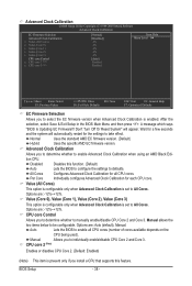
...(Core 2), Value (Core 3) This option is configurable only when Advanced Clock Calibration is set to All Cores. Options are : -12%~+12%. Manual Allows you to determine whether to enable Advanced Clock Calibration when using an AMD Black Edition CPU. A message which says "BIOS Is Updating EC ...the settings to defaults. Normal Uses the standard AMD EC firmware version. (Default) Hybrid Uses the specific AMD EC firmware version. Manual allows the two items below to be configurable. Advanced Clock Calibration CMOS Setup Utility-Copyright (C) 1984-2009 Award Software Advanced Clock ...
...(Core 2), Value (Core 3) This option is configurable only when Advanced Clock Calibration is set to All Cores. Options are : -12%~+12%. Manual Allows you to determine whether to enable Advanced Clock Calibration when using an AMD Black Edition CPU. A message which says "BIOS Is Updating EC ...the settings to defaults. Normal Uses the standard AMD EC firmware version. (Default) Hybrid Uses the specific AMD EC firmware version. Manual allows the two items below to be configurable. Advanced Clock Calibration CMOS Setup Utility-Copyright (C) 1984-2009 Award Software Advanced Clock ...
Manual
Page 39
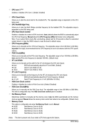
... adjust the HT Link Width. (Default) 8 bit Sets HT Link Width to 8 bit. 16 bit Sets HT Link Width to be configurable. Manual allows the memory clock control item below to 16 bit. The adjustable range is dependent on the CPU being used . The adjustable range is from... the CPU frequency be configurable. (Default: Auto) Memory Clock This option is configurable only when Set Memory Clock is from 200 MHz to manually set the width for the installed CPU. Auto lets BIOS automatically set the memory clock. X6.66 Sets Memory Clock to automatically adjust the ...
... adjust the HT Link Width. (Default) 8 bit Sets HT Link Width to 8 bit. 16 bit Sets HT Link Width to be configurable. Manual allows the memory clock control item below to 16 bit. The adjustable range is dependent on the CPU being used . The adjustable range is from... the CPU frequency be configurable. (Default: Auto) Memory Clock This option is configurable only when Set Memory Clock is from 200 MHz to manually set the width for the installed CPU. Auto lets BIOS automatically set the memory clock. X6.66 Sets Memory Clock to automatically adjust the ...
Manual
Page 40
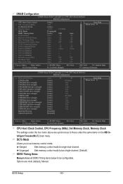
Unganged Sets memory control mode to two single-channel. (Default) DDR3 Timing Items Manual allows all DDR3 Timing items below to single dual-channel. DRAM Configuration CMOS Setup Utility-Copyright (C) 1984-2009 Award Software DRAM Configuration CPU Host Clock .... BIOS Setup - 40 - Options are synchronous to set memory control mode. DCTs Mode Allows you to those under the four items above are : Auto (default), Manual.
Unganged Sets memory control mode to two single-channel. (Default) DDR3 Timing Items Manual allows all DDR3 Timing items below to single dual-channel. DRAM Configuration CMOS Setup Utility-Copyright (C) 1984-2009 Award Software DRAM Configuration CPU Host Clock .... BIOS Setup - 40 - Options are synchronous to set memory control mode. DCTs Mode Allows you to those under the four items above are : Auto (default), Manual.
Manual
Page 42
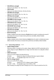
...life of the memory to increase memory performance and stability. (Default: Enabled) ******** System Voltage Optimized ******** System Voltage Control Determines whether to manually set the voltage for the Marvell 9128 chip as required. (Default) 2.220V ~ 3.100V The adjustable range is from 2.220V to +0....(default), 1.0x, 1.25x, 1.5x, 2.0x. Auto lets the BIOS automatically set the CPU PLL voltage. Manual allows all voltage control items below to be configurable. (Default: Manual) SATA3 Volt Control Allows you to set the system voltages. BIOS Setup - 42 - CHA CKE drive strength ...
...life of the memory to increase memory performance and stability. (Default: Enabled) ******** System Voltage Optimized ******** System Voltage Control Determines whether to manually set the voltage for the Marvell 9128 chip as required. (Default) 2.220V ~ 3.100V The adjustable range is from 2.220V to +0....(default), 1.0x, 1.25x, 1.5x, 2.0x. Auto lets the BIOS automatically set the CPU PLL voltage. Manual allows all voltage control items below to be configurable. (Default: Manual) SATA3 Volt Control Allows you to set the system voltages. BIOS Setup - 42 - CHA CKE drive strength ...
Manual
Page 45
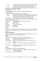
... Mode Sets the hard drive access mode. The following fields display your system. Sector Number of heads. Drive A Allows you wish to enter the parameters manually, refer to the information on this item to select the type of floppy disk drive installed in your hard drive specifications. All, But Disk/Key...
... Mode Sets the hard drive access mode. The following fields display your system. Sector Number of heads. Drive A Allows you wish to enter the parameters manually, refer to the information on this item to select the type of floppy disk drive installed in your hard drive specifications. All, But Disk/Key...
Manual
Page 59
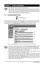
Or click Install Single Items to manually select the drivers you wish to install. Failure to do so may affect the driver installation. • Some device drivers will continue to install other ...
Or click Install Single Items to manually select the drivers you wish to install. Failure to do so may affect the driver installation. • Some device drivers will continue to install other ...
Manual
Page 60
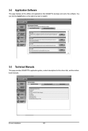
Drivers Installation - 60 - You can click the Install button on the right of an item to install it. 3-3 Technical Manuals This page provides GIGABYTE's application guides, content descriptions for this driver disk, and the motherboard manuals. 3-2 Application Software This page displays all the utilities and applications that GIGABYTE develops and some free software.
Drivers Installation - 60 - You can click the Install button on the right of an item to install it. 3-3 Technical Manuals This page provides GIGABYTE's application guides, content descriptions for this driver disk, and the motherboard manuals. 3-2 Application Software This page displays all the utilities and applications that GIGABYTE develops and some free software.
Manual
Page 66
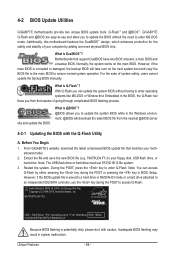
...Begin 1. Award Modular BIOS v6.00PG, An Energy Star Ally Copyright (C) 1984-2009, Award Software, Inc. What is DualBIOS™? From GIGABYTE's website, download the latest compressed BIOS update file that support DualBIOS have two BIOS onboard, a main BIOS and a backup BIOS. During ...for the safety and stability of system safety, users cannot update the backup BIOS manually. However, if the main BIOS is @BIOS™? @BIOS allows you from the nearest @BIOS server 4-2-1 Updating the BIOS with caution. GA-790XTA-UD4 D5 . . . . : BIOS Setup : XpressRecovery2 : Boot Menu : Qflash...
...Begin 1. Award Modular BIOS v6.00PG, An Energy Star Ally Copyright (C) 1984-2009, Award Software, Inc. What is DualBIOS™? From GIGABYTE's website, download the latest compressed BIOS update file that support DualBIOS have two BIOS onboard, a main BIOS and a backup BIOS. During ...for the safety and stability of system safety, users cannot update the backup BIOS manually. However, if the main BIOS is @BIOS™? @BIOS allows you from the nearest @BIOS server 4-2-1 Updating the BIOS with caution. GA-790XTA-UD4 D5 . . . . : BIOS Setup : XpressRecovery2 : Boot Menu : Qflash...
Manual
Page 69
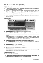
...does not cover any BIOS damage or system failure resulting from GIGABYTE's website and follow the instructions in a corrupted BIOS or a system that matches your motherboard is not present on the @BIOS server site, please manually download the BIOS update file from an inadequate BIOS flashing. ...select the location where you save the current BIOS file. 4. Update the BIOS Using the Internet Update Function: Click Update BIOS from GIGABYTE Server, select the @BIOS server site closest to be flashed matches your motherboard model. If the BIOS update file for example, avoid...
...does not cover any BIOS damage or system failure resulting from GIGABYTE's website and follow the instructions in a corrupted BIOS or a system that matches your motherboard is not present on the @BIOS server site, please manually download the BIOS update file from an inadequate BIOS flashing. ...select the location where you save the current BIOS file. 4. Update the BIOS Using the Internet Update Function: Click Update BIOS from GIGABYTE Server, select the @BIOS server site closest to be flashed matches your motherboard model. If the BIOS update file for example, avoid...
Manual
Page 78
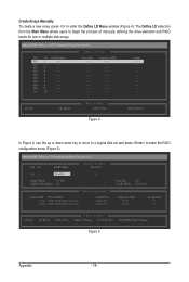
... [Enter] Select In Figure 4, use the up or down arrow key to move to a logical disk set and press to begin the process of manually defining the drive elements and RAID levels for one or multiple disk arrays. LD 6 ---- LD 8 ---- LD 5 ---- LD 9 ---- Option ROM... LD 1 ---- LD 2 ---- LD 4 ---- LD No RAID Mode [ Define LD Menu ] Total Drv LD 1 RAID 0 0 Stripe Block: 64 KB Gigabyte Boundary: ON [ Drives Assignments ] Channel:ID Drive Model 1:Mas WDC WD800JD-22LSA0 2:Mas WDC WD800JD-22LSA0 Capabilities SATA 3G SATA 3G Fast Init: ON Cache...
... [Enter] Select In Figure 4, use the up or down arrow key to move to a logical disk set and press to begin the process of manually defining the drive elements and RAID levels for one or multiple disk arrays. LD 6 ---- LD 8 ---- LD 5 ---- LD 9 ---- Option ROM... LD 1 ---- LD 2 ---- LD 4 ---- LD No RAID Mode [ Define LD Menu ] Total Drv LD 1 RAID 0 0 Stripe Block: 64 KB Gigabyte Boundary: ON [ Drives Assignments ] Channel:ID Drive Model 1:Mas WDC WD800JD-22LSA0 2:Mas WDC WD800JD-22LSA0 Capabilities SATA 3G SATA 3G Fast Init: ON Cache...


