Manual
Page 3
... Revision The revision number on how to the specifications and features in this manual may be made by GIGABYTE without GIGABYTE's prior written permission. Example: For instructions on your motherboard revision before updating motherboard BIOS, drivers, or when looking for technical information. No part of the product, read the Quick Installation Guide included...
... Revision The revision number on how to the specifications and features in this manual may be made by GIGABYTE without GIGABYTE's prior written permission. Example: For instructions on your motherboard revision before updating motherboard BIOS, drivers, or when looking for technical information. No part of the product, read the Quick Installation Guide included...
Manual
Page 4
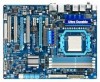
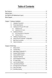
Table of Contents Box Contents...6 Optional Items...6 GA-790XTA-UD4 Motherboard Layout 7 Block Diagram...8 Chapter 1 Hardware Installation 9 1-1 Installation Precautions 9 1-2 Product Specifications 10 1-3 Installing the CPU and CPU Cooler 13...ATI CrossFireX™ Configuration 19 1-7 Back Panel Connectors 20 1-8 Internal Connectors 22 Chapter 2 BIOS Setup 33 2-1 Startup Screen 34 2-2 The Main Menu 35 2-3 MB Intelligent Tweaker(M.I.T 37 2-4 Standard CMOS Features 44 2-5 Advanced BIOS Features 46 2-6 Integrated Peripherals 48 2-7 Power Management Setup 52 2-8 PC Health Status 54...
Table of Contents Box Contents...6 Optional Items...6 GA-790XTA-UD4 Motherboard Layout 7 Block Diagram...8 Chapter 1 Hardware Installation 9 1-1 Installation Precautions 9 1-2 Product Specifications 10 1-3 Installing the CPU and CPU Cooler 13...ATI CrossFireX™ Configuration 19 1-7 Back Panel Connectors 20 1-8 Internal Connectors 22 Chapter 2 BIOS Setup 33 2-1 Startup Screen 34 2-2 The Main Menu 35 2-3 MB Intelligent Tweaker(M.I.T 37 2-4 Standard CMOS Features 44 2-5 Advanced BIOS Features 46 2-6 Integrated Peripherals 48 2-7 Power Management Setup 52 2-8 PC Health Status 54...
Manual
Page 5
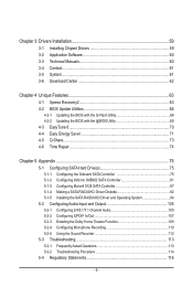
... 60 3-3 Technical Manuals 60 3-4 Contact...61 3-5 System...61 3-6 Download Center 62 Chapter 4 Unique Features 63 4-1 Xpress Recovery2 63 4-2 BIOS Update Utilities 66 4-2-1 Updating the BIOS with the Q-Flash Utility 66 4-2-2 Updating the BIOS with the @BIOS Utility 69 4-3 EasyTune 6...70 4-4 Easy Energy Saver 71 4-5 Q-Share...73 4-6 Time Repair...74 Chapter 5 Appendix...75 5-1 Configuring SATA...
... 60 3-3 Technical Manuals 60 3-4 Contact...61 3-5 System...61 3-6 Download Center 62 Chapter 4 Unique Features 63 4-1 Xpress Recovery2 63 4-2 BIOS Update Utilities 66 4-2-1 Updating the BIOS with the Q-Flash Utility 66 4-2-2 Updating the BIOS with the @BIOS Utility 69 4-3 EasyTune 6...70 4-4 Easy Energy Saver 71 4-5 Q-Share...73 4-6 Time Repair...74 Chapter 5 Appendix...75 5-1 Configuring SATA...
Manual
Page 8
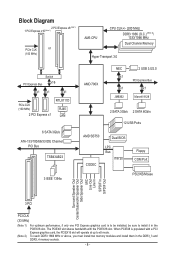
... 3 IEEE 1394a AMD 790X NEC x1 x1 JMB362 2 USB 3.0/2.0 PCI Express Bus x1 Marvell 9128 2 SATA 3Gb/s 2 SATA 6Gb/s 12 USB Ports AMD SB750 Dual BIOS CODEC LPC Bus IT8720 Floppy COM Port PS/2 KB/Mouse Surround Speaker Out Center/Subwoofer Speaker Out Side Speaker Out MIC Line Out Line In...
... 3 IEEE 1394a AMD 790X NEC x1 x1 JMB362 2 USB 3.0/2.0 PCI Express Bus x1 Marvell 9128 2 SATA 3Gb/s 2 SATA 6Gb/s 12 USB Ports AMD SB750 Dual BIOS CODEC LPC Bus IT8720 Floppy COM Port PS/2 KB/Mouse Surround Speaker Out Center/Subwoofer Speaker Out Side Speaker Out MIC Line Out Line In...
Manual
Page 12
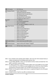
... DDR3 1866 MHz or above, you install. (Note 5) Available functions in the PCIEX16 slot. When PCIEX8 is populated with the PCIEX16 slot. I/O Controller w Hardware Monitor w w w w w w BIOS w w w w Unique Features w w w w w w w w w w Bundled Software w iTE IT8720 chip System voltage detection CPU/System temperature detection CPU/System/Power fan speed detection CPU overheating warning CPU/System...
... DDR3 1866 MHz or above, you install. (Note 5) Available functions in the PCIEX16 slot. When PCIEX8 is populated with the PCIEX16 slot. I/O Controller w Hardware Monitor w w w w w w BIOS w w w w Unique Features w w w w w w w w w w Bundled Software w iTE IT8720 chip System voltage detection CPU/System temperature detection CPU/System/Power fan speed detection CPU overheating warning CPU/System...
Manual
Page 16
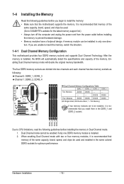
After the memory is installed, the BIOS will double the original memory bandwidth. Enabling Dual Channel memory mode will automatically detect the specifications and capacity of the memory. The four DDR3 memory .../SS Four Modules DS/SS DS/SS DS/SS DS/SS (SS=Single-Sided, DS=Double-Sided, "- -"=No Memory) If two memory modules are to GIGABYTE's website for optimum performance. 1-4 Installing the Memory Read the following guidelines before you are divided into two channels and each channel has two memory sockets...
After the memory is installed, the BIOS will double the original memory bandwidth. Enabling Dual Channel memory mode will automatically detect the specifications and capacity of the memory. The four DDR3 memory .../SS Four Modules DS/SS DS/SS DS/SS DS/SS (SS=Single-Sided, DS=Double-Sided, "- -"=No Memory) If two memory modules are to GIGABYTE's website for optimum performance. 1-4 Installing the Memory Read the following guidelines before you are divided into two channels and each channel has two memory sockets...
Manual
Page 18
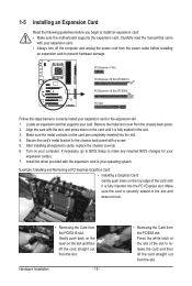
... Express x1 Slot PCI Express x16 Slot (PCIEX16) PCI Express x16 Slot (PCIEX8) PCI Slot Follow the steps below to make any required BIOS changes for your card. Turn on the top edge of the slot to release the card and then lift the card straight out from the... expansion card: • Make sure the motherboard supports the expansion card. After installing all expansion cards, replace the chassis cover(s). 6. If necessary, go to BIOS Setup to correctly install your expansion card. • Always turn off the computer and unplug the power cord from the chassis back panel. 2. Secure the...
... Express x1 Slot PCI Express x16 Slot (PCIEX16) PCI Express x16 Slot (PCIEX8) PCI Slot Follow the steps below to make any required BIOS changes for your card. Turn on the top edge of the slot to release the card and then lift the card straight out from the... expansion card: • Make sure the motherboard supports the expansion card. After installing all expansion cards, replace the chassis cover(s). 6. If necessary, go to BIOS Setup to correctly install your expansion card. • Always turn off the computer and unplug the power cord from the chassis back panel. 2. Secure the...
Manual
Page 26
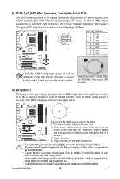
... negative side (-) of the SATA 3Gb/s cable to your SATA hard drive. 10) BAT (Battery) The battery provides power to keep the values (such as BIOS configurations, date, and time information) in the CMOS when the computer is replaced with SATA 3Gb/s and SATA 1.5Gb/s standards. Turn off . Hardware Installation - ... wait for one . Danger of hard drives must be lost. 9) GSATA3_6/7 (SATA 6Gb/s Connectors, Controlled by Marvell 9128) The SATA connectors conform to Chapter 2, "BIOS Setup," "Integrated Peripherals," and Chapter 5, "Configuring SATA Hard Drive(s)," for 5 seconds.) 3.
... negative side (-) of the SATA 3Gb/s cable to your SATA hard drive. 10) BAT (Battery) The battery provides power to keep the values (such as BIOS configurations, date, and time information) in the CMOS when the computer is replaced with SATA 3Gb/s and SATA 1.5Gb/s standards. Turn off . Hardware Installation - ... wait for one . Danger of hard drives must be lost. 9) GSATA3_6/7 (SATA 6Gb/s Connectors, Controlled by Marvell 9128) The SATA connectors conform to Chapter 2, "BIOS Setup," "Integrated Peripherals," and Chapter 5, "Configuring SATA Hard Drive(s)," for 5 seconds.) 3.

Manual
Page 27
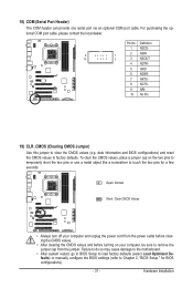
... LED, hard drive activity LED, speaker and etc. RESRES+ CICI+ PWR+ PWR- When connecting your system using the power switch (refer to Chapter 2, "BIOS Setup," "Power Management Setup," for information about beep codes. • HD (Hard Drive Activity LED, Blue) Connects to the speaker on the chassis front ...panel. The LED is on when the hard drive is detected, the BIOS may differ by issuing a beep code. The LED keeps blinking when the sys- The front panel design may issue beeps in different patterns to...
... LED, hard drive activity LED, speaker and etc. RESRES+ CICI+ PWR+ PWR- When connecting your system using the power switch (refer to Chapter 2, "BIOS Setup," "Power Management Setup," for information about beep codes. • HD (Hard Drive Activity LED, Blue) Connects to the speaker on the chassis front ...panel. The LED is on when the hard drive is detected, the BIOS may differ by issuing a beep code. The LED keeps blinking when the sys- The front panel design may issue beeps in different patterns to...
Manual
Page 31
... from the jumper. Failure to do so may cause damage to the motherboard. • After system restart, go to BIOS Setup to load factory defaults (select Load Optimized Defaults) or manually configure the BIOS settings (refer to factory defaults. Definition 1 NDCD- 9 1 2 NSIN 10 2 3 NSOUT 4 NDTR- 5 GND 6 NDSR- 7 ... turning on the two pins to temporarily short the two pins or use a metal object like a screwdriver to touch the two pins for BIOS configurations). - 31 - Pin No. Open: Normal Short: Clear CMOS Values • Always turn off your computer, be sure to clear...
... from the jumper. Failure to do so may cause damage to the motherboard. • After system restart, go to BIOS Setup to load factory defaults (select Load Optimized Defaults) or manually configure the BIOS settings (refer to factory defaults. Definition 1 NDCD- 9 1 2 NSIN 10 2 3 NSOUT 4 NDTR- 5 GND 6 NDSR- 7 ... turning on the two pins to temporarily short the two pins or use a metal object like a screwdriver to touch the two pins for BIOS configurations). - 31 - Pin No. Open: Normal Short: Clear CMOS Values • Always turn off your computer, be sure to clear...
Manual
Page 33
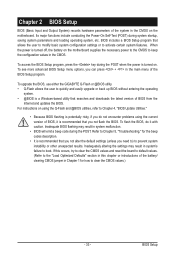
...the battery on the motherboard. Refer to Chapter 5, "Troubleshooting," for how to clear the CMOS values.) - 33 - Chapter 2 BIOS Setup BIOS (Basic Input and Output System) records hardware parameters of the system in system's failure to boot. Inadequately altering the settings may result ... settings or to quickly and easily upgrade or back up BIOS without entering the operating system. • @BIOS is potentially risky, if you not flash the BIOS. To upgrade the BIOS, use either the GIGABYTE Q-Flash or @BIOS utility. • Q-Flash allows the user to activate certain...
...the battery on the motherboard. Refer to Chapter 5, "Troubleshooting," for how to clear the CMOS values.) - 33 - Chapter 2 BIOS Setup BIOS (Basic Input and Output System) records hardware parameters of the system in system's failure to boot. Inadequately altering the settings may result ... settings or to quickly and easily upgrade or back up BIOS without entering the operating system. • @BIOS is potentially risky, if you not flash the BIOS. To upgrade the BIOS, use either the GIGABYTE Q-Flash or @BIOS utility. • Q-Flash allows the user to activate certain...
Manual
Page 34
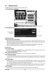
..., then press to Xpress Recovery2 during the POST, telling you do not respond YES or NO in time. To show the BIOS POST screen. BIOS Setup - 34 - Motherboard Model BIOS Version GA-790XTA-UD4 D4 . . . . : BIOS Setup : XpressRecovery2 : Boot Menu : Qflash 10/28/2009-RD780-SB750-7A66AG00C-00 Function Keys Function Keys SATA Mode Message: "SATA is...
..., then press to Xpress Recovery2 during the POST, telling you do not respond YES or NO in time. To show the BIOS POST screen. BIOS Setup - 34 - Motherboard Model BIOS Version GA-790XTA-UD4 D4 . . . . : BIOS Setup : XpressRecovery2 : Boot Menu : Qflash 10/28/2009-RD780-SB750-7A66AG00C-00 Function Keys Function Keys SATA Mode Message: "SATA is...
Manual
Page 35
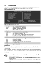
...& Exit Setup Exit Without Saving ESC: Quit F8: Q-Flash Select Item F10: Save & Exit Setup Change CPU's Clock & Voltage F11: Save CMOS to BIOS F12: Load CMOS from BIOS BIOS Setup Program Function Keys Move the selection bar to select an item Execute command or enter the submenu Main Menu: Exit the... Menu Help The on the screen. Press to exit the help screen (General Help) of function keys available for reference only and may differ by BIOS version. - 35 - 2-2 The Main Menu Once you want in the Main Menu or a submenu, press + to access more advanced options. • When the...
...& Exit Setup Exit Without Saving ESC: Quit F8: Q-Flash Select Item F10: Save & Exit Setup Change CPU's Clock & Voltage F11: Save CMOS to BIOS F12: Load CMOS from BIOS BIOS Setup Program Function Keys Move the selection bar to select an item Execute command or enter the submenu Main Menu: Exit the... Menu Help The on the screen. Press to exit the help screen (General Help) of function keys available for reference only and may differ by BIOS version. - 35 - 2-2 The Main Menu Once you want in the Main Menu or a submenu, press + to access more advanced options. • When the...
Manual
Page 36
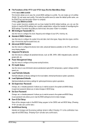
...carry out this menu to configure the system time and date, hard drive types, floppy disk drive types, and the type of reconfiguring the BIOS settings. A supervisor password allows you to restrict access to configure all peripheral devices, such as IDE, SATA, USB, integrated audio, and ... F12: Load CMOS from a profile created before, without the hassles of errors that stop the system boot, etc. Advanced BIOS Features Use this menu to configure the device boot order, advanced features available on the CPU, and the primary display adapter. Integrated Peripherals...
...carry out this menu to configure the system time and date, hard drive types, floppy disk drive types, and the type of reconfiguring the BIOS settings. A supervisor password allows you to restrict access to configure all peripheral devices, such as IDE, SATA, USB, integrated audio, and ... F12: Load CMOS from a profile created before, without the hassles of errors that stop the system boot, etc. Advanced BIOS Features Use this menu to configure the device boot order, advanced features available on the CPU, and the primary display adapter. Integrated Peripherals...

Manual
Page 37
... Help F7: Optimized Defaults • Whether the system will work stably with the overclock/overvoltage settings you made is dependent on your overall system configurations. BIOS Setup Incorrectly doing overclock/overvoltage may result in system's failure to boot. If this occurs, clear the CMOS values and reset the board to default...
... Help F7: Optimized Defaults • Whether the system will work stably with the overclock/overvoltage settings you made is dependent on your overall system configurations. BIOS Setup Incorrectly doing overclock/overvoltage may result in system's failure to boot. If this occurs, clear the CMOS values and reset the board to default...
Manual
Page 38
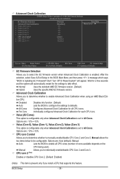
... when Advanced Clock Calibration is set to enable Advanced Clock Calibration when using an AMD Black Edition CPU. A message which says "BIOS Is Updating EC Firmware!!! Normal Uses the standard AMD EC firmware version. (Default) Hybrid Uses the specific AMD EC firmware version....%~+12%. CPU core Control Allows you to determine whether to All Cores. Advanced Clock Calibration Allows you to determine whether to take effect. BIOS Setup - 38 - Per Core Individually configures Advanced Clock Calibration for the settings to manually enable/disable CPU Core 2 and Core 3. All...
... when Advanced Clock Calibration is set to enable Advanced Clock Calibration when using an AMD Black Edition CPU. A message which says "BIOS Is Updating EC Firmware!!! Normal Uses the standard AMD EC firmware version. (Default) Hybrid Uses the specific AMD EC firmware version....%~+12%. CPU core Control Allows you to determine whether to All Cores. Advanced Clock Calibration Allows you to determine whether to take effect. BIOS Setup - 38 - Per Core Individually configures Advanced Clock Calibration for the settings to manually enable/disable CPU Core 2 and Core 3. All...
Manual
Page 39
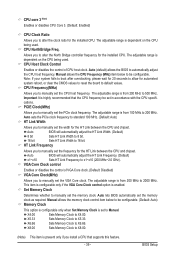
...you to alter the North Bridge controller frequency for the installed CPU. The adjustable range is highly recommended that supports this feature. - 39 - BIOS Setup Manual allows the CPU Frequency (MHz) item below to be configurable. (Default: Auto) Memory Clock This option is configurable only when Set... adjust the CPU host frequency. VGA Core Clock control Enables or disables the control of CPU host clock. Auto (default) allows the BIOS to X5.33. HT Link Frequency Allows you to manually set the memory clock. Set Memory Clock Determines whether to X8.00. (Note...
...you to alter the North Bridge controller frequency for the installed CPU. The adjustable range is highly recommended that supports this feature. - 39 - BIOS Setup Manual allows the CPU Frequency (MHz) item below to be configurable. (Default: Auto) Memory Clock This option is configurable only when Set... adjust the CPU host frequency. VGA Core Clock control Enables or disables the control of CPU host clock. Auto (default) allows the BIOS to X5.33. HT Link Frequency Allows you to manually set the memory clock. Set Memory Clock Determines whether to X8.00. (Note...
Manual
Page 40
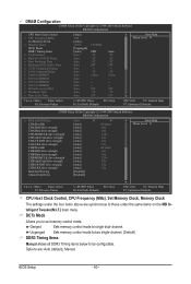
... CPU Host Clock Control, CPU Frequency (MHz), Set Memory Clock, Memory Clock The settings under the same items on the MB Intelligent Tweaker(M.I.T.) main menu. BIOS Setup - 40 -
... CPU Host Clock Control, CPU Frequency (MHz), Set Memory Clock, Memory Clock The settings under the same items on the MB Intelligent Tweaker(M.I.T.) main menu. BIOS Setup - 40 -
Manual
Page 41
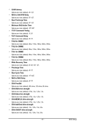
... : Auto (default), 4T~12T. Write Recovery Time Options are : Auto (default), 90ns, 110ns, 160ns, 300ns, 350ns. Row Precharge Time Options are : Auto (default), 4T~7T. BIOS Setup Precharge Time Options are : Auto (default), 5T~12T. CHA Data drive strength Options are : Auto (default), 0.75x, 1.0x, 1.25x, 1.5x. CHA MEMCLK drive strength...
... : Auto (default), 4T~12T. Write Recovery Time Options are : Auto (default), 90ns, 110ns, 160ns, 300ns, 350ns. Row Precharge Time Options are : Auto (default), 4T~7T. BIOS Setup Precharge Time Options are : Auto (default), 5T~12T. CHA Data drive strength Options are : Auto (default), 0.75x, 1.0x, 1.25x, 1.5x. CHA MEMCLK drive strength...
Manual
Page 42
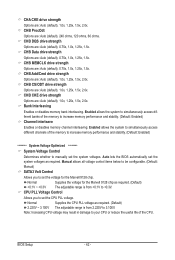
...), 1.0x, 1.25x, 1.5x, 2.0x. CHB Add/Cmd drive strength Options are : Auto (default), 1.0x, 1.25x, 1.5x, 2.0x. Auto lets the BIOS automatically set the voltage for the Marvell 9128 chip. BIOS Setup - 42 - CHB ProcOdt Options are: Auto (default), 240 ohms, 120 ohms, 60 ohms. CHB DQS drive strength Options are : Auto...
...), 1.0x, 1.25x, 1.5x, 2.0x. CHB Add/Cmd drive strength Options are : Auto (default), 1.0x, 1.25x, 1.5x, 2.0x. Auto lets the BIOS automatically set the voltage for the Marvell 9128 chip. BIOS Setup - 42 - CHB ProcOdt Options are: Auto (default), 240 ohms, 120 ohms, 60 ohms. CHB DQS drive strength Options are : Auto...


