
Manual
Page 3
... "REV: 1.0" means the revision of GIGABYTE. The trademarks mentioned in the use GIGABYTE's unique features, read or download the information..., check on our website at: http://www.gigabyte.com.tw Identifying Your Motherboard Revision The revision number on how to use of this product, GIGABYTE provides the following types of this manual may .... Copyright © 2009 GIGA-BYTE TECHNOLOGY CO., LTD. Disclaimer Information in any form or by GIGABYTE without GIGABYTE's prior written permission. Example: All rights reserved. No part of documentations: For detailed product...
... "REV: 1.0" means the revision of GIGABYTE. The trademarks mentioned in the use GIGABYTE's unique features, read or download the information..., check on our website at: http://www.gigabyte.com.tw Identifying Your Motherboard Revision The revision number on how to use of this product, GIGABYTE provides the following types of this manual may .... Copyright © 2009 GIGA-BYTE TECHNOLOGY CO., LTD. Disclaimer Information in any form or by GIGABYTE without GIGABYTE's prior written permission. Example: All rights reserved. No part of documentations: For detailed product...
Manual
Page 4
...GA-73PVM-S2 Motherboard Layout 7 Block Diagram ...8 Chapter 1 Hardware Installation 9 1-1 Installation Precautions 9 1-2 Product Specifications 10 1-3 Installing the CPU and CPU Cooler 13 1-3-1 Installing the CPU 13 1-3-2 Installing the CPU Cooler 15 1-4 Installing the Memory 16 1-4-1 Installing a Memory 16 1-5 Installing an Expansion Card 17 1-6 Back Panel Connectors 18 1-7 Internal Connectors 20 Chapter 2 BIOS... Setup 31 2-1 Startup Screen 32 2-2 The Main Menu 33 2-3 Standard CMOS Features 35 2-4 Advanced BIOS Features 37 2-5 IntegratedPeripherals...
...GA-73PVM-S2 Motherboard Layout 7 Block Diagram ...8 Chapter 1 Hardware Installation 9 1-1 Installation Precautions 9 1-2 Product Specifications 10 1-3 Installing the CPU and CPU Cooler 13 1-3-1 Installing the CPU 13 1-3-2 Installing the CPU Cooler 15 1-4 Installing the Memory 16 1-4-1 Installing a Memory 16 1-5 Installing an Expansion Card 17 1-6 Back Panel Connectors 18 1-7 Internal Connectors 20 Chapter 2 BIOS... Setup 31 2-1 Startup Screen 32 2-2 The Main Menu 33 2-3 Standard CMOS Features 35 2-4 Advanced BIOS Features 37 2-5 IntegratedPeripherals...
Manual
Page 5
... 56 3-3 Driver CD Information 56 3-4 Hardware Information 57 3-5 Contact Us ...57 Chapter 4 Unique Features 59 4-1 Xpress Recovery2 59 4-2 BIOS Update Utilities 64 4-2-1 Updating the BIOS with the Q-Flash Utility 64 4-2-2 Updating the BIOS with the @BIOS Utility 67 4-3 EasyTune 5 ...69 4-4 Windows Vista ReadyBoost 70 Chapter 5 Appendix ...71 5-1 Configuring SATA Hard Drive(s 71 5-1-1 Configuring the...
... 56 3-3 Driver CD Information 56 3-4 Hardware Information 57 3-5 Contact Us ...57 Chapter 4 Unique Features 59 4-1 Xpress Recovery2 59 4-2 BIOS Update Utilities 64 4-2-1 Updating the BIOS with the Q-Flash Utility 64 4-2-2 Updating the BIOS with the @BIOS Utility 67 4-3 EasyTune 5 ...69 4-4 Windows Vista ReadyBoost 70 Chapter 5 Appendix ...71 5-1 Configuring SATA Hard Drive(s 71 5-1-1 Configuring the...
Manual
Page 7
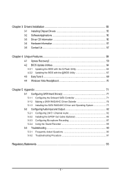
GA-73PVM-S2 Motherboard Layout KB_MS ATX_12V LGA775 CPU_FAN DDRII1 DDRII2 DVI LPT LAN VGA USB R_USB RTL8211B AUDIO F_AUDIO BIOS CLR_CMOS PCIE_1 nVIDIA® GeForce 7100/ nForce 630i PCIE_16 IT8718 PCI1 SPDIF_O CODEC PCI2 CD_IN COMA F_USB1 F_USB2 FDD ATX IDE GA-73PVM-S2 SATAII0 SATAII2 SATAII1 SATAII3 CI PWR_LED F_PANEL BAT SYS_FAN - 7 -
GA-73PVM-S2 Motherboard Layout KB_MS ATX_12V LGA775 CPU_FAN DDRII1 DDRII2 DVI LPT LAN VGA USB R_USB RTL8211B AUDIO F_AUDIO BIOS CLR_CMOS PCIE_1 nVIDIA® GeForce 7100/ nForce 630i PCIE_16 IT8718 PCI1 SPDIF_O CODEC PCI2 CD_IN COMA F_USB1 F_USB2 FDD ATX IDE GA-73PVM-S2 SATAII0 SATAII2 SATAII1 SATAII3 CI PWR_LED F_PANEL BAT SYS_FAN - 7 -
Manual
Page 8
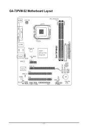
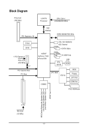
Block Diagram PCIe CLK (100 MHz) LGA775 Processor CPU CLK+/(333/266/200 MHz) PCI Express x16 Host Interface DDR2 800/667/533 MHz D-Sub DVI-D 1 PCI Express x1 PCIe CLK (100 MHz) x1 PCI Express Bus PCI Bus ATA-133/100/66/33 IDE Channel 4 SATA 3Gb/s nVIDIA® GeForce 7100/ nForce 630i 10 USB Ports RTL 8211B LAN RJ45 CODEC LPC BUS IT8718 BIOS Floppy LPT Port COM Port PS/2 KB/Mouse MIC(Center/Subwoofer Speaker Out) Line-Out(Front Speaker Out) Line-In(Rear Speaker Out) SPDIF Out 2 PCI PCI CLK (33 MHz) - 8 -
Block Diagram PCIe CLK (100 MHz) LGA775 Processor CPU CLK+/(333/266/200 MHz) PCI Express x16 Host Interface DDR2 800/667/533 MHz D-Sub DVI-D 1 PCI Express x1 PCIe CLK (100 MHz) x1 PCI Express Bus PCI Bus ATA-133/100/66/33 IDE Channel 4 SATA 3Gb/s nVIDIA® GeForce 7100/ nForce 630i 10 USB Ports RTL 8211B LAN RJ45 CODEC LPC BUS IT8718 BIOS Floppy LPT Port COM Port PS/2 KB/Mouse MIC(Center/Subwoofer Speaker Out) Line-Out(Front Speaker Out) Line-In(Rear Speaker Out) SPDIF Out 2 PCI PCI CLK (33 MHz) - 8 -
Manual
Page 11
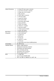
.../System temperature detection Š CPU/System fan speed detection Š CPU overheating warning Š CPU/System fan fail warning Š CPU fan speed control (Note 1) BIOS Š 1 x 4 Mbit flash Š Use of licensed AWARD...
.../System temperature detection Š CPU/System fan speed detection Š CPU overheating warning Š CPU/System fan fail warning Š CPU fan speed control (Note 1) BIOS Š 1 x 4 Mbit flash Š Use of licensed AWARD...
Manual
Page 12
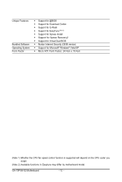
... Center Š Support for Q-Flash Š Support for EasyTune (Note 2) Š Support for Xpress Install Š Support for Xpress Recovery2 Š Support for Virtual Dual BIOS Š Norton Internet Security (OEM version) Š Support for Microsoft® Windows® Vista/XP Š Micro ATX Form Factor; 24.4cm x 19.4cm (Note... CPU fan speed control function is supported will depend on the CPU cooler you install. (Note 2) Available functions in Easytune may differ by motherboard model. GA-73PVM-S2 Motherboard - 12 -
... Center Š Support for Q-Flash Š Support for EasyTune (Note 2) Š Support for Xpress Install Š Support for Xpress Recovery2 Š Support for Virtual Dual BIOS Š Norton Internet Security (OEM version) Š Support for Microsoft® Windows® Vista/XP Š Micro ATX Form Factor; 24.4cm x 19.4cm (Note... CPU fan speed control function is supported will depend on the CPU cooler you install. (Note 2) Available functions in Easytune may differ by motherboard model. GA-73PVM-S2 Motherboard - 12 -

Manual
Page 17
... computer. Secure the card's metal bracket to the chassis back panel with the expansion card in the expansion slot. 1. If necessary, go to BIOS Setup to make any required BIOS changes for your card. Hardware Installation Remove the metal slot cover from the slot. - 17 - Carefully read the manual that supports your...
... computer. Secure the card's metal bracket to the chassis back panel with the expansion card in the expansion slot. 1. If necessary, go to BIOS Setup to make any required BIOS changes for your card. Hardware Installation Remove the metal slot cover from the slot. - 17 - Carefully read the manual that supports your...
Manual
Page 24
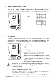
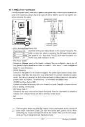
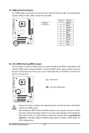
... with an incorrect model. • Contact the place of purchase or local dealer if you are not able to keep the values (such as BIOS configurations, date, and time information) in the CMOS when the computer is turned off. The LED keeps blinking when the system is in the ...S5). Definition 1 MPD+ 1 2 MPD- 3 MPD- You may be lost. Plug in S1 sleep state. The LED is on the chassis to indicate system power status. GA-73PVM-S2 Motherboard - 24 - System Status LED S0 On S1 Blinking S3/S4/S5 Off 9) BAT (BATTERY) The battery provides power to replace the battery by removing...
... with an incorrect model. • Contact the place of purchase or local dealer if you are not able to keep the values (such as BIOS configurations, date, and time information) in the CMOS when the computer is turned off. The LED keeps blinking when the system is in the ...S5). Definition 1 MPD+ 1 2 MPD- 3 MPD- You may be lost. Plug in S1 sleep state. The LED is on the chassis to indicate system power status. GA-73PVM-S2 Motherboard - 24 - System Status LED S0 On S1 Blinking S3/S4/S5 Off 9) BAT (BATTERY) The battery provides power to replace the battery by removing...
Manual
Page 25
... and the pin assignments are matched correctly. - 25 - The system reports system startup status by chassis. If a problem is detected, the BIOS may differ by issuing a beep code. The LED is on when the hard drive is operating. One single short beep will be heard if...; PW (Power Switch): Connects to the speaker on the chassis front panel. When connecting your system using the power switch (refer to Chapter 2, "BIOS Setup," "Power Management Setup," for information about beep codes. • HD (IDE Hard Drive Activity LED) Connects to this header according to the pin...
... and the pin assignments are matched correctly. - 25 - The system reports system startup status by chassis. If a problem is detected, the BIOS may differ by issuing a beep code. The LED is on when the hard drive is operating. One single short beep will be heard if...; PW (Power Switch): Connects to the speaker on the chassis front panel. When connecting your system using the power switch (refer to Chapter 2, "BIOS Setup," "Power Management Setup," for information about beep codes. • HD (IDE Hard Drive Activity LED) Connects to this header according to the pin...
Manual
Page 28
... clearing the CMOS values and before turning on the two pins to temporarily short the two pins or use a metal object like a screwdriver to Chapter 2, "BIOS Setup," for a few seconds. Failure to do so may cause damage to the motherboard. • After system restart, go to... to factory defaults. Open: Normal Short: Clear CMOS Values • Always turn off your computer, be sure to remove the jumper cap from the jumper. GA-73PVM-S2 Motherboard - 28 -
... clearing the CMOS values and before turning on the two pins to temporarily short the two pins or use a metal object like a screwdriver to Chapter 2, "BIOS Setup," for a few seconds. Failure to do so may cause damage to the motherboard. • After system restart, go to... to factory defaults. Open: Normal Short: Clear CMOS Values • Always turn off your computer, be sure to remove the jumper cap from the jumper. GA-73PVM-S2 Motherboard - 28 -
Manual
Page 31
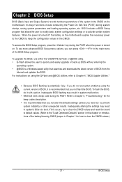
... on . To see more advanced BIOS Setup menu options, you do it is recommended that allows the user to modify basic system configuration settings or to keep the configuration values in the CMOS. To upgrade the BIOS, use either the GIGABYTE Q-Flash or @BIOS utility. • Q-Flash allows the... user to quickly and easily upgrade or back up BIOS without entering the operating system. • @BIOS is potentially risky, if you can press + in the ...
... on . To see more advanced BIOS Setup menu options, you do it is recommended that allows the user to modify basic system configuration settings or to keep the configuration values in the CMOS. To upgrade the BIOS, use either the GIGABYTE Q-Flash or @BIOS utility. • Q-Flash allows the... user to quickly and easily upgrade or back up BIOS without entering the operating system. • @BIOS is potentially risky, if you can press + in the ...
Manual
Page 32
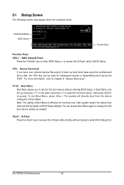
... access Boot Menu again to change the first boot device setting as needed. : Q-Flash Press the key to access the Q-Flash utility directly without entering BIOS Setup. GA-73PVM-S2 Motherboard - 32 - Note: The setting in Boot Menu. The system will still be used for one time only. Motherboard Model...
... access Boot Menu again to change the first boot device setting as needed. : Q-Flash Press the key to access the Q-Flash utility directly without entering BIOS Setup. GA-73PVM-S2 Motherboard - 32 - Note: The setting in Boot Menu. The system will still be used for one time only. Motherboard Model...
Manual
Page 33
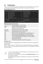
... description of a highlighted setup option is displayed on the right side of the submenu. • If you do not find the settings you enter the BIOS Setup program, the Main Menu (as usual, select the Load Optimized Defaults item to set your system to its defaults. • The...: Quit F8: Q-Flash KLJI: Select Item F10: Save & Exit Setup Time, Date, Hard Disk Type... Submenu Help While in a submenu, press to display a help screen. BIOS Setup 2-2 The Main Menu Once you want in the Main Menu or a submenu, press + to access more advanced options. • When the system is in...
... description of a highlighted setup option is displayed on the right side of the submenu. • If you do not find the settings you enter the BIOS Setup program, the Main Menu (as usual, select the Load Optimized Defaults item to set your system to its defaults. • The...: Quit F8: Q-Flash KLJI: Select Item F10: Save & Exit Setup Time, Date, Hard Disk Type... Submenu Help While in a submenu, press to display a help screen. BIOS Setup 2-2 The Main Menu Once you want in the Main Menu or a submenu, press + to access more advanced options. • When the system is in...
Manual
Page 34
...you to make changes. „ Save & Exit Setup Save all the changes made in the BIOS Setup program to the CMOS and exit BIOS Setup. (Pressing can also carry out this task.) GA-73PVM-S2 Motherboard - 34 - A supervisor password allows you to restrict access to the confirmation message will... exit BIOS Setup. (Pressing can also carry out this task.) „ Exit Without Saving Abandon all ...
...you to make changes. „ Save & Exit Setup Save all the changes made in the BIOS Setup program to the CMOS and exit BIOS Setup. (Pressing can also carry out this task.) GA-73PVM-S2 Motherboard - 34 - A supervisor password allows you to restrict access to the confirmation message will... exit BIOS Setup. (Pressing can also carry out this task.) „ Exit Without Saving Abandon all ...
Manual
Page 35
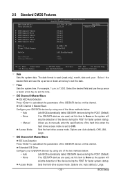
...this channel. IDE Channel 0 Master/Slave Configure your IDE/SATA devices by using one of the two methods below : • Auto • None Lets BIOS automatically detect IDE/SATA devices during the POST for faster system startup. Options are : Auto (default), Large. - 35 - For example, 1 p.m. ...hard drive access mode. Extended IDE Drive Configure your IDE/SATA devices by using one of the three methods below : • Auto Lets BIOS automatically detect IDE/SATA devices during the POST for faster system startup. 2-3 Standard CMOS Features Date (mm:dd:yy) Time (hh:mm...
...this channel. IDE Channel 0 Master/Slave Configure your IDE/SATA devices by using one of the two methods below : • Auto • None Lets BIOS automatically detect IDE/SATA devices during the POST for faster system startup. Options are : Auto (default), Large. - 35 - For example, 1 p.m. ...hard drive access mode. Extended IDE Drive Configure your IDE/SATA devices by using one of the three methods below : • Auto Lets BIOS automatically detect IDE/SATA devices during the POST for faster system startup. 2-3 Standard CMOS Features Date (mm:dd:yy) Time (hh:mm...
Manual
Page 36
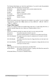
... Number of sectors. Sector Number of heads. Memory These fields are read-only and are : Disabled (default), Drive A. GA-73PVM-S2 Motherboard - 36 - Precomp Write precompensation cylinder. Extended Memory The amount of the currently installed hard drive. Floppy 3 Mode ... the installed floppy disk drive is 3-mode floppy disk drive, a Japanese standard floppy disk drive. Options are determined by the BIOS POST. Cylinder Number of floppy disk drive installed in your hard drive specifications. Base Memory Also called conventional memory. All, But...
... Number of sectors. Sector Number of heads. Memory These fields are read-only and are : Disabled (default), Drive A. GA-73PVM-S2 Motherboard - 36 - Precomp Write precompensation cylinder. Extended Memory The amount of the currently installed hard drive. Floppy 3 Mode ... the installed floppy disk drive is 3-mode floppy disk drive, a Japanese standard floppy disk drive. Options are determined by the BIOS POST. Cylinder Number of floppy disk drive installed in your hard drive specifications. Base Memory Also called conventional memory. All, But...
Manual
Page 37
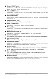
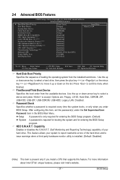
... Capability Enables or disables the S.M.A.R.T. (Self Monitoring and Reporting Technology) capability of your system to move it up or down on the list. BIOS Setup This feature allows your hard drive. Use the up or down arrow key to select a hard drive, then press the plus key (or...LS120, Hard Disk, CDROM, ZIP, USB-FDD, USB-ZIP, USB-CDROM, USB-HDD, Legacy LAN, Disabled. Setup A password is only required for entering the BIOS Setup program. (Default) System A password is required every time the system boots, or only when you install a CPU that supports this feature. HDD S.M.A.R.T. For...
... Capability Enables or disables the S.M.A.R.T. (Self Monitoring and Reporting Technology) capability of your system to move it up or down on the list. BIOS Setup This feature allows your hard drive. Use the up or down arrow key to select a hard drive, then press the plus key (or...LS120, Hard Disk, CDROM, ZIP, USB-FDD, USB-ZIP, USB-CDROM, USB-HDD, Legacy LAN, Disabled. Setup A password is only required for entering the BIOS Setup program. (Default) System A password is required every time the system boots, or only when you install a CPU that supports this feature. HDD S.M.A.R.T. For...

Manual
Page 39
...) Onboard VGA Sets the onboard VGA as the first display. - 39 - MS-DOS, for example, will use only this memory for the onboard graphics controller. BIOS Setup Init Display First Specifies the first initiation of system memory allocated solely for display. PEG Sets PCI Express graphics card as the first display...
...) Onboard VGA Sets the onboard VGA as the first display. - 39 - MS-DOS, for example, will use only this memory for the onboard graphics controller. BIOS Setup Init Display First Specifies the first initiation of system memory allocated solely for display. PEG Sets PCI Express graphics card as the first display...

Manual
Page 41
... network card instead of using the onboard audio, set to RAID. (Default: Enabled) SATA-II Sec-Master RAID Enables or disables RAID for USB devices. BIOS Setup USB Keyboard Support Allows USB keyboard to be used in audio card instead of memory allocated for the third SATA 3Gb/s connector (SATAII2). Advanced...
... network card instead of using the onboard audio, set to RAID. (Default: Enabled) SATA-II Sec-Master RAID Enables or disables RAID for USB devices. BIOS Setup USB Keyboard Support Allows USB keyboard to be used in audio card instead of memory allocated for the third SATA 3Gb/s connector (SATAII2). Advanced...


