
User Manual
Page 2
... of Content Item Checklist 4 WARNING 4 Chapter 1 Introduction 5 Summary of Features 5 GA-2CEWH Motherboard Layout 7 Chapter 2 Hardware Installation Process 9 Step 1: Installing Processor and CPU Cooling Fan 10 Step1-1: Installing CPU 10 ..., cabinet wires, and power supply .......... 17 Step4-1:I/O Back Panel Introduction 17 Step4-2: Connectors Introduction 20 Chapter 3 BIOS Setup 35 Main ...37 Advanced 41 Hardware Monitoring ...42 BIOS Event Logging ...43 Processor ...44 Hammer Configuration ...45 Chipset ...48 Diskette Controller ...49 ATAController ...50 Integrated Network ...
... of Content Item Checklist 4 WARNING 4 Chapter 1 Introduction 5 Summary of Features 5 GA-2CEWH Motherboard Layout 7 Chapter 2 Hardware Installation Process 9 Step 1: Installing Processor and CPU Cooling Fan 10 Step1-1: Installing CPU 10 ..., cabinet wires, and power supply .......... 17 Step4-1:I/O Back Panel Introduction 17 Step4-2: Connectors Introduction 20 Chapter 3 BIOS Setup 35 Main ...37 Advanced 41 Hardware Monitoring ...42 BIOS Event Logging ...43 Processor ...44 Hammer Configuration ...45 Chipset ...48 Diskette Controller ...49 ATAController ...50 Integrated Network ...
User Manual
Page 6
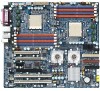
GA-2CEWH Motherboard On-Board Peripherals RAID Supported Hardware Monitor Power Managerment Features IEEE1394A Audio On-Board LAN PS/2 Connector BIOS Additional Features 1 Floppy port supports 2 FDD with 360K, 720K,1.2M, 1.44M and 2.88M bytes. 1 Parallel port supports Normal/EPP/ECP mode 1 Serial port (COM) 8 x USB 2.0 2 x ..., mouse Supports ACPI S1/S3/S4/S5 functions TI TSB43AB23 ALC 850 Boradcom BCM 5751T & 5011U phy PS/2 Keyboard interface and PS/2 Mouse interface Phoenix BIOS on 8Mb flash RAM SMBus Support IOAPIC Support Serial IRQ Support AC Recovery 6
GA-2CEWH Motherboard On-Board Peripherals RAID Supported Hardware Monitor Power Managerment Features IEEE1394A Audio On-Board LAN PS/2 Connector BIOS Additional Features 1 Floppy port supports 2 FDD with 360K, 720K,1.2M, 1.44M and 2.88M bytes. 1 Parallel port supports Normal/EPP/ECP mode 1 Serial port (COM) 8 x USB 2.0 2 x ..., mouse Supports ACPI S1/S3/S4/S5 functions TI TSB43AB23 ALC 850 Boradcom BCM 5751T & 5011U phy PS/2 Keyboard interface and PS/2 Mouse interface Phoenix BIOS on 8Mb flash RAM SMBus Support IOAPIC Support Serial IRQ Support AC Recovery 6
User Manual
Page 8
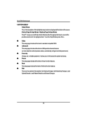
... Profession 20503. ITE IT8712F-A 7. IO4_FAN I. DIMM 0~3 R. SATA1 18. AUX_IN 25. FAN4 (Front Fan) F. IDE2 10. SATA3 16. FAN5 (CPU1 Fan) E. FAN3 (Rear Fan) G. SATA2 15. GA-2CEWH Motherboard A. CENTER_SOUOUND C. AMD8132 5. BIOS 8. F_USB2 13. DIMM4~7 Q. AUDIO S. USB_LAN1 U. CI 21. F_AUDIO 23. LPT X. ATX1 (SSI power connector) 27.
... Profession 20503. ITE IT8712F-A 7. IO4_FAN I. DIMM 0~3 R. SATA1 18. AUX_IN 25. FAN4 (Front Fan) F. IDE2 10. SATA3 16. FAN5 (CPU1 Fan) E. FAN3 (Rear Fan) G. SATA2 15. GA-2CEWH Motherboard A. CENTER_SOUOUND C. AMD8132 5. BIOS 8. F_USB2 13. DIMM4~7 Q. AUDIO S. USB_LAN1 U. CI 21. F_AUDIO 23. LPT X. ATX1 (SSI power connector) 27.

User Manual
Page 9
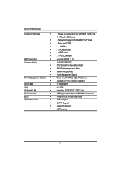
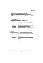
Connect ribbon cables, cabinet wires, and power supply Step 5- Install expansion cards Step 4- Setup BIOS software Step 6- Install supporting software tools Step 3 Step 2 Step 5 Step 4 Step 1 Step 4 Step 4 Step 1 Step 2 9 Hardware Installation Process Chapter 2 Hardware Installation Process To set up your computer, you must complete the following steps: Step 1- Install memory modules Step 3- Install the Central Processing Unit (CPU) Step 2-
Connect ribbon cables, cabinet wires, and power supply Step 5- Install expansion cards Step 4- Setup BIOS software Step 6- Install supporting software tools Step 3 Step 2 Step 5 Step 4 Step 1 Step 4 Step 4 Step 1 Step 2 9 Hardware Installation Process Chapter 2 Hardware Installation Process To set up your computer, you must complete the following steps: Step 1- Install memory modules Step 3- Install the Central Processing Unit (CPU) Step 2-

User Manual
Page 13
... and size. To install the memory module, just push it vertically into the DIMM socket .The DIMM module can only fit in one notches. The BIOS will cause improper installation. Step 2: Install memory modules Hardware Installation Process Before installing the processor and heatsink, adhere to the following warning: Please note that...
... and size. To install the memory module, just push it vertically into the DIMM socket .The DIMM module can only fit in one notches. The BIOS will cause improper installation. Step 2: Install memory modules Hardware Installation Process Before installing the processor and heatsink, adhere to the following warning: Please note that...
User Manual
Page 16
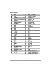
..., if necessary, setup BIOS utility of the expansion card. 6. Power on the card are indeed seated in motherboard. 4. Read the related expansion card's instruction document before install the expansion card into expansion slot in the slot. 5. Replace the screw to secure the slot bracket of expansion card from BIOS. 8. GA-2CEWH Motherboard Step 3: Install...
..., if necessary, setup BIOS utility of the expansion card. 6. Power on the card are indeed seated in motherboard. 4. Read the related expansion card's instruction document before install the expansion card into expansion slot in the slot. 5. Replace the screw to secure the slot bracket of expansion card from BIOS. 8. GA-2CEWH Motherboard Step 3: Install...
User Manual
Page 25
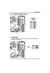
Pin No. 1 2 3 Definition GND INTRUDER# NC 25 H / I / J / K ) SATA0/1/2/3 (Serial ATA Connector) Connector Introduction 1 7 SATA0~3 Pin No. 1 2 3 4 5 6 7 Definition GND TXP TXN GND RXN RXP GND SATA0~3 L ) CI (CASE OPEN) This 3 pin connector allows your system to enable or disable the "case open" item in BIOS if the system case begin remove.
Pin No. 1 2 3 Definition GND INTRUDER# NC 25 H / I / J / K ) SATA0/1/2/3 (Serial ATA Connector) Connector Introduction 1 7 SATA0~3 Pin No. 1 2 3 4 5 6 7 Definition GND TXP TXN GND RXN RXP GND SATA0~3 L ) CI (CASE OPEN) This 3 pin connector allows your system to enable or disable the "case open" item in BIOS if the system case begin remove.

User Manual
Page 34
GA-2CEWH Motherboard 5 ) CLR_CMOS1 (Clear CMOS Function) You may clear the CMOS data to prevent from improper use this jumper. To clear CMOS, temporarily short 1-2 pin. 1 1-2 close: Clear CMOS 1 2-3 close: Normal (Default) 6 ) BIOS_RE (BIOS Recovery Function) 1 1-2 close: Enable BIOS Recovery function 1 2-3 close: Disable BIOS Recovery function (Default) 34 Default value doesn't include the "Shunter" to its default values by this jumper.
GA-2CEWH Motherboard 5 ) CLR_CMOS1 (Clear CMOS Function) You may clear the CMOS data to prevent from improper use this jumper. To clear CMOS, temporarily short 1-2 pin. 1 1-2 close: Clear CMOS 1 2-3 close: Normal (Default) 6 ) BIOS_RE (BIOS Recovery Function) 1 1-2 close: Enable BIOS Recovery function 1 2-3 close: Disable BIOS Recovery function (Default) 34 Default value doesn't include the "Shunter" to its default values by this jumper.

User Manual
Page 35
... hand Move to enter Setup. Quit and not save changes into CMOS Status Page Setup Menu and Option Page Setup Menu - This type of the BIOS Setup Program. CONTROL KEYS Move to previous item Move to next item Move to the item in battery-backed CMOS RAM so that allows users... Defaults Reserved Reserved Save all the CMOS changes, only for Main Menu 35 Exit current page and return to modify the basic system configuration. Chapter 3 BIOS Setup BIOS Setup BIOS Setup is turned off.
... hand Move to enter Setup. Quit and not save changes into CMOS Status Page Setup Menu and Option Page Setup Menu - This type of the BIOS Setup Program. CONTROL KEYS Move to previous item Move to next item Move to the item in battery-backed CMOS RAM so that allows users... Defaults Reserved Reserved Save all the CMOS changes, only for Main Menu 35 Exit current page and return to modify the basic system configuration. Chapter 3 BIOS Setup BIOS Setup BIOS Setup is turned off.
User Manual
Page 36
... This setup page includes all the items in standard compatible BIOS. z Exit There are five optionsin this selection: Exit Saving Changes, Exit Discarding Changes, Load Optimal Defaults, Load Failsafe Defaults, and Discard Changes. 36 To exit the Help Window press . GA-2CEWH Motherboard GETTINGHELP Main Menu The on-line description of the highlighted...
... This setup page includes all the items in standard compatible BIOS. z Exit There are five optionsin this selection: Exit Saving Changes, Exit Discarding Changes, Load Optimal Defaults, Load Failsafe Defaults, and Discard Changes. 36 To exit the Help Window press . GA-2CEWH Motherboard GETTINGHELP Main Menu The on-line description of the highlighted...

User Manual
Page 37
... Menu + -: Change Values F5: Setup Defaults Enter: Select Sub-Menu F10: Save&Exit Figure 1: Main System Time The time is calculated based on the screen. BIOS Setup Main Once you set the date. (Weekend: DD: MM: YY) (YY: 1099~2099) Note!! Use arrow keys to select among the items and press... to accept or enter the sub-menu. " "Indicates DISPLAY ONLY 37 Note that the "Day" automatically changed after you enter Phoenix BIOS Setup Utility, the Main Menu (Figure 1) will appear on the 24-hour military time clock. Set the System Time (HH:MM:SS) System Date Set...
... Menu + -: Change Values F5: Setup Defaults Enter: Select Sub-Menu F10: Save&Exit Figure 1: Main System Time The time is calculated based on the screen. BIOS Setup Main Once you set the date. (Weekend: DD: MM: YY) (YY: 1099~2099) Note!! Use arrow keys to select among the items and press... to accept or enter the sub-menu. " "Indicates DISPLAY ONLY 37 Note that the "Day" automatically changed after you enter Phoenix BIOS Setup Utility, the Main Menu (Figure 1) will appear on the 24-hour military time clock. Set the System Time (HH:MM:SS) System Date Set...
User Manual
Page 39
... that you will use commonly . 39 Maximum Capacity This field displays the maximum capacity of the device in the specific IDE channel support LBA Mode. BIOS Setup Multi-Sector Transfer This field displays the information of Teansfer Mode. Installed OS This category allows you to max imize the IDE data transfer...
... that you will use commonly . 39 Maximum Capacity This field displays the maximum capacity of the device in the specific IDE channel support LBA Mode. BIOS Setup Multi-Sector Transfer This field displays the information of Teansfer Mode. Installed OS This category allows you to max imize the IDE data transfer...
User Manual
Page 40
.... This is the amount of the base memory is present during the POST. GA-2CEWH Motherboard System Information This category includes the information of base (or conventional) memory installed in the C PU's memory address map. 40 Extended Memory The BIOS determines how much extended memory is typically 512K for systems with 512K memory...
.... This is the amount of the base memory is present during the POST. GA-2CEWH Motherboard System Information This category includes the information of base (or conventional) memory installed in the C PU's memory address map. 40 Extended Memory The BIOS determines how much extended memory is typically 512K for systems with 512K memory...

User Manual
Page 41
...'s default boot-up sequence, keyboard operation, chipset configuration, PCI configuration and System Hardware health monitoring. 41 BIOS Setup Advanced Phoenix TrustedCore(tm) Setup Utility Main Advanced Security Power Boot Exit Hardware Monitoring Item Specific Help BIOS Event Logging Processor Hammer Configuration Chipset Diskette Controller ATA Controller Integrated Network Interface Integrated Audio Integrated...
...'s default boot-up sequence, keyboard operation, chipset configuration, PCI configuration and System Hardware health monitoring. 41 BIOS Setup Advanced Phoenix TrustedCore(tm) Setup Utility Main Advanced Security Power Boot Exit Hardware Monitoring Item Specific Help BIOS Event Logging Processor Hammer Configuration Chipset Diskette Controller ATA Controller Integrated Network Interface Integrated Audio Integrated...

User Manual
Page 43
...Disabled] F1: Help Esc: Exit KL: Select Item IJ: Select Menu + -: Change Values F5: Setup Defaults Enter: Select Sub-Menu F10: Save&Exit Figure 2-2: BIOS Event Logging Boot Event Logging Enabled When this function. 43 Disabled Disable this item is set to enabld, all system errors will be logged to... BIOS event log. (Default vaule) Disabled Error will not be logged to enabled, system will clear BIOS event log after rebooting system. View DMI external Log Press [Enter] to view the contents of ...
...Disabled] F1: Help Esc: Exit KL: Select Item IJ: Select Menu + -: Change Values F5: Setup Defaults Enter: Select Sub-Menu F10: Save&Exit Figure 2-2: BIOS Event Logging Boot Event Logging Enabled When this function. 43 Disabled Disable this item is set to enabld, all system errors will be logged to... BIOS event log. (Default vaule) Disabled Error will not be logged to enabled, system will clear BIOS event log after rebooting system. View DMI external Log Press [Enter] to view the contents of ...
User Manual
Page 45
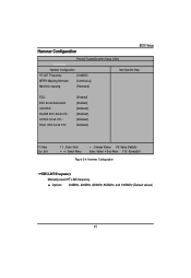
Hammer Configuration BIOS Setup PhoenixTrustedCore(tm) Setup Utility Advanced Hammer Configuration Item Specific Help HT-LDT Frequency: [100MHz] MTRR Mapping Methods: [Continuous] Memhole mapping [Hardware] ECC: ECC Scrub ...
Hammer Configuration BIOS Setup PhoenixTrustedCore(tm) Setup Utility Advanced Hammer Configuration Item Specific Help HT-LDT Frequency: [100MHz] MTRR Mapping Methods: [Continuous] Memhole mapping [Hardware] ECC: ECC Scrub ...
User Manual
Page 47
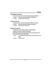
BIOS Setup DCACHE ECC Scrub CTL This option allows user to set the rates of background scrubbing for L2 cache lines. Disabled Disable this function. (Default ...
BIOS Setup DCACHE ECC Scrub CTL This option allows user to set the rates of background scrubbing for L2 cache lines. Disabled Disable this function. (Default ...

User Manual
Page 48
... Enabled All memory modules in the system support parity ECC mode. NODE Memory Interleaving Auto BIOS will automatically detect capability on each node. (Default value) Disabled Disable this function. GA-2CEWH Motherboard Chipset Advanced Chipset DRAM Bank Interleaving NODE memory Interleaving ACPI SRAT Table ECC Memory Checking...Select Menu + -: Change Values F5: Setup Defaults Enter: Select Sub-Menu F10: Save&Exit Figure 2-5: Chipset DRAM Bank Interleaving Auto BIOS will automatically detect capability on each node. (Default value) Disabled Disable this function.
... Enabled All memory modules in the system support parity ECC mode. NODE Memory Interleaving Auto BIOS will automatically detect capability on each node. (Default value) Disabled Disable this function. GA-2CEWH Motherboard Chipset Advanced Chipset DRAM Bank Interleaving NODE memory Interleaving ACPI SRAT Table ECC Memory Checking...Select Menu + -: Change Values F5: Setup Defaults Enter: Select Sub-Menu F10: Save&Exit Figure 2-5: Chipset DRAM Bank Interleaving Auto BIOS will automatically detect capability on each node. (Default value) Disabled Disable this function.
User Manual
Page 49
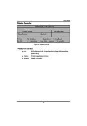
Disabled Disable this function. 49 Diskette Controller Advanced Diskette Controller Diskette Controller BIOS Setup PhoenixTrustedCore(tm) Setup Utility [Enabled] Item Specific Help F1: Help Esc: Exit KL: Select Item IJ: Select Menu + -: Change Values F5: Setup Defaults Enter: Select Sub-Menu F10: Save&Exit Figure 2-6: Diskette Controller Diskette Controller Auto BIOS will automatically start configuration for floppy diskette controller. (Default value) Enabled Enable floppy diskette controller.
Disabled Disable this function. 49 Diskette Controller Advanced Diskette Controller Diskette Controller BIOS Setup PhoenixTrustedCore(tm) Setup Utility [Enabled] Item Specific Help F1: Help Esc: Exit KL: Select Item IJ: Select Menu + -: Change Values F5: Setup Defaults Enter: Select Sub-Menu F10: Save&Exit Figure 2-6: Diskette Controller Diskette Controller Auto BIOS will automatically start configuration for floppy diskette controller. (Default value) Enabled Enable floppy diskette controller.

User Manual
Page 51
..., 00A0h, 00C0h, 00Eh. 51 Option ROM Scan Enabled Enableing this item to initialize device expansion ROM. (Defualt value) Disabled Disable this function. Integrated Network Interface BIOS Setup PhoenixTrustedCore(tm) Setup Utility Advanced Integrated Network Interface Item Specific Help Integrated Network Interface 1 (Broadcom) Integrated Network Interface 2 (NVDIA) F1: Help Esc: Exit KL...
..., 00A0h, 00C0h, 00Eh. 51 Option ROM Scan Enabled Enableing this item to initialize device expansion ROM. (Defualt value) Disabled Disable this function. Integrated Network Interface BIOS Setup PhoenixTrustedCore(tm) Setup Utility Advanced Integrated Network Interface Item Specific Help Integrated Network Interface 1 (Broadcom) Integrated Network Interface 2 (NVDIA) F1: Help Esc: Exit KL...


