Manual
Page 4
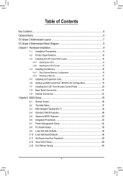
Table of Contents Box Contents...6 Optional Items...6 G1.Sniper 2 Motherboard Layout 7 G1.Sniper 2 Motherboard Block Diagram 8 Chapter 1 Hardware Installation 9 1-1 Installation Precautions 9 1-2 Product Specifications 10 1-3 Installing the CPU and CPU Cooler 13 1-3-1 Installing the CPU 13 1-3-2 Installing the CPU Cooler 15 1-4 Installing the Memory 16 1-4-1 Dual Channel Memory Configuration 16 1-4-2 Installing a Memory ... 2-9 Load Fail-Safe Defaults 58 2-10 Load Optimized Defaults 58 2-11 Set Supervisor/User Password 59 2-12 Save & Exit Setup 60 2-13 Exit Without Saving 60 - 4 -
Table of Contents Box Contents...6 Optional Items...6 G1.Sniper 2 Motherboard Layout 7 G1.Sniper 2 Motherboard Block Diagram 8 Chapter 1 Hardware Installation 9 1-1 Installation Precautions 9 1-2 Product Specifications 10 1-3 Installing the CPU and CPU Cooler 13 1-3-1 Installing the CPU 13 1-3-2 Installing the CPU Cooler 15 1-4 Installing the Memory 16 1-4-1 Dual Channel Memory Configuration 16 1-4-2 Installing a Memory ... 2-9 Load Fail-Safe Defaults 58 2-10 Load Optimized Defaults 58 2-11 Set Supervisor/User Password 59 2-12 Save & Exit Setup 60 2-13 Exit Without Saving 60 - 4 -
Manual
Page 13
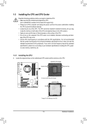
...cord from the power outlet before you begin to install the CPU: •• Make sure that the motherboard supports the CPU. (Go to GIGABYTE's website for the peripherals. It is not installed, otherwise overheating and dam- Locate the alignment keys on the motherboard CPU socket and the notches... on the CPU - 13 - Hardware Installation age of the CPU. •• Do not turn on the computer if the CPU cooler is not recommended that the ...
...cord from the power outlet before you begin to install the CPU: •• Make sure that the motherboard supports the CPU. (Go to GIGABYTE's website for the peripherals. It is not installed, otherwise overheating and dam- Locate the alignment keys on the motherboard CPU socket and the notches... on the CPU - 13 - Hardware Installation age of the CPU. •• Do not turn on the computer if the CPU cooler is not recommended that the ...
Manual
Page 23
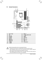
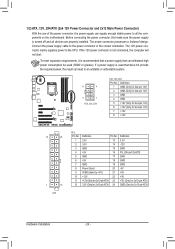
... 8 7 6 7 4 10 11 4 12 14 18 15 9 19 1) ATX_12V_2X4 2) ATX 3) CPU_FAN 4) FAN1/2/3/4 5) HP_PWR 6) SATA3_0/1 7) SATA2_2/3/4 8) GSATA3_6/7 9) F_PANEL 10) F_AUDIO 11) SPDIF_O 12) F_USB1/F_USB2/F_USB3 13) F_USB30 14) COMA 15) CLR_CMOS 16) BAT 17) PHASE LED 18) TPM 19) OC_BUTTON_F Read the following guidelines before turning on the computer, make sure ...
... 8 7 6 7 4 10 11 4 12 14 18 15 9 19 1) ATX_12V_2X4 2) ATX 3) CPU_FAN 4) FAN1/2/3/4 5) HP_PWR 6) SATA3_0/1 7) SATA2_2/3/4 8) GSATA3_6/7 9) F_PANEL 10) F_AUDIO 11) SPDIF_O 12) F_USB1/F_USB2/F_USB3 13) F_USB30 14) COMA 15) CLR_CMOS 16) BAT 17) PHASE LED 18) TPM 19) OC_BUTTON_F Read the following guidelines before turning on the computer, make sure ...
Manual
Page 24
... 12V) 3 GND 4 GND 5 +12V (Only for 2x4-pin 12V) 6 +12V (Only for 2x4-pin 12V) 7 +12V 8 +12V 12 24 1 13 ATX ATX: Pin No. 1 2 3 4 5 6 7 8 9 10 11 12 Definition Pin No. 3.3V 13 3.3V 14 GND 15 +5V 16 GND 17 +5V 18 GND 19 Power Good 20 5VSB (stand by +5V) 21...
... 12V) 3 GND 4 GND 5 +12V (Only for 2x4-pin 12V) 6 +12V (Only for 2x4-pin 12V) 7 +12V 8 +12V 12 24 1 13 ATX ATX: Pin No. 1 2 3 4 5 6 7 8 9 10 11 12 Definition Pin No. 3.3V 13 3.3V 14 GND 15 +5V 16 GND 17 +5V 18 GND 19 Power Good 20 5VSB (stand by +5V) 21...
Manual
Page 30
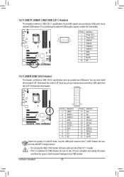
... (5V) 2 Power (5V) 9 1 10 2 3 USB DX- 4 USB DY- 5 USB DX+ 6 USB DY+ 7 GND 8 GND 9 No Pin 10 NC F_USB30 F_AUDIO(H) 13) F_USB30 (USB 3.0/2.0 Header) The header conforms to USB 2.0/1.1 specification. For purchasing the optional USB bracket, please contact the local dealer. Hardware Installation - 30 - You can... 20 Pin No. Definition 1 VBUS 2 TPMSSRX13 w/hSouSsRinXg 1+ 4 GND 5 SSTX16 SSTX1+ 7 GND 8 D19 D1+ 10 NC Pin No. 11 12 13 14 15 16 17 18 19 20 Definition D2+ D2GND SSTX2+ SSTX2GND SSRX2+ SSRX2VBUS No Pin Voltage measurement module(X58A-OC) PCIe power connector (SATA...
... (5V) 2 Power (5V) 9 1 10 2 3 USB DX- 4 USB DY- 5 USB DX+ 6 USB DY+ 7 GND 8 GND 9 No Pin 10 NC F_USB30 F_AUDIO(H) 13) F_USB30 (USB 3.0/2.0 Header) The header conforms to USB 2.0/1.1 specification. For purchasing the optional USB bracket, please contact the local dealer. Hardware Installation - 30 - You can... 20 Pin No. Definition 1 VBUS 2 TPMSSRX13 w/hSouSsRinXg 1+ 4 GND 5 SSTX16 SSTX1+ 7 GND 8 D19 D1+ 10 NC Pin No. 11 12 13 14 15 16 17 18 19 20 Definition D2+ D2GND SSTX2+ SSTX2GND SSRX2+ SSRX2VBUS No Pin Voltage measurement module(X58A-OC) PCIe power connector (SATA...
Manual
Page 33
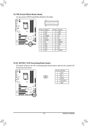
... VCC3 LAD1 1 Voltage measurement module(X58A-OC) PWM Swi DIP 2 DIP Pin No. Definition 1 23 11 LAD0 12 GND PCIe power connector (SATA)(X58A-OC) 13 NC 14 ID 15 SB3V 16 SERIRQ 17 GND 18 NC 19 NC 20 SUSCLK 19) OC_BUTTON_F (CPU Overclocking Button Header) This header connects to...
... VCC3 LAD1 1 Voltage measurement module(X58A-OC) PWM Swi DIP 2 DIP Pin No. Definition 1 23 11 LAD0 12 GND PCIe power connector (SATA)(X58A-OC) 13 NC 14 ID 15 SB3V 16 SERIRQ 17 GND 18 NC 19 NC 20 SUSCLK 19) OC_BUTTON_F (CPU Overclocking Button Header) This header connects to...
Manual
Page 48
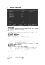
... skip the detection of the currently installed hard drive. is week (read-only), month, date and year. Head Number of cylinders. The date format is 13:0:0. Select the desired field and use the up arrow or down arrow key to None so the system will skip the detection of the device...
... skip the detection of the currently installed hard drive. is week (read-only), month, date and year. Head Number of cylinders. The date format is 13:0:0. Select the desired field and use the up arrow or down arrow key to None so the system will skip the detection of the device...
Manual
Page 60
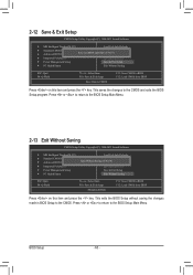
... Abandon all Data F11: Save CMOS to the CMOS and exits the BIOS Setup program. Press or to return to the BIOS Setup Main Menu. 2-13 Exit Without Saving CMOS Setup Utility-Copyright (C) 1984-2011 Award Software MB Intelligent Tweaker(M.I .T.) Load Fail-Safe Defaults Standard CMOS Features Advanced...
... Abandon all Data F11: Save CMOS to the CMOS and exits the BIOS Setup program. Press or to return to the BIOS Setup Main Menu. 2-13 Exit Without Saving CMOS Setup Utility-Copyright (C) 1984-2011 Award Software MB Intelligent Tweaker(M.I .T.) Load Fail-Safe Defaults Standard CMOS Features Advanced...
Manual
Page 73
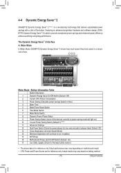
...Application will light on motherboard model. • CPU Power and Power Scores are for reference only. Meter Mode In Meter Mode, GIGABYTE Dynamic Energy Saver™ 2 shows how much power they have saved in taskbar) 15 INFO/Help 16 Motherboard Phase LED On/Off...The above data is for reference only. riod of the button. 4-4 Dynamic Energy Saver™ 2 GIGABYTE Dynamic Energy Saver™ 2 (Note 1) is a revolutionary technology that delivers unparalleled power savings with a click of time. 13 14 15 3 2 4 76 5 1 8 9 11 12 10 16 17 Meter Mode - Featuring...
...Application will light on motherboard model. • CPU Power and Power Scores are for reference only. Meter Mode In Meter Mode, GIGABYTE Dynamic Energy Saver™ 2 shows how much power they have saved in taskbar) 15 INFO/Help 16 Motherboard Phase LED On/Off...The above data is for reference only. riod of the button. 4-4 Dynamic Energy Saver™ 2 GIGABYTE Dynamic Energy Saver™ 2 (Note 1) is a revolutionary technology that delivers unparalleled power savings with a click of time. 13 14 15 3 2 4 76 5 1 8 9 11 12 10 16 17 Meter Mode - Featuring...
Manual
Page 74
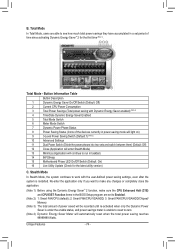
... in taskbar) 14 INFO/Help 15 Motherboard Phase LED On/Off Switch (Default: On) 16 Live Utility Update (Check for the first time (Note 3). 12 13 14 3 2 4 65 7 1 8 15 10 11 9 16 Total Mode - Button Information Table Button Description 1 Dynamic Energy Saver On/Off Switch (Default: Off) 2 Current CPU Power ...Settings 11 Dual Power Switch (Divide the power phases into two sets and switch between them) (Default: Off) 12 Close (Application will enter Stealth Mode) 13 Minimize (Application will automatically reset when the total power saving reaches 99999999 Watts.
... in taskbar) 14 INFO/Help 15 Motherboard Phase LED On/Off Switch (Default: On) 16 Live Utility Update (Check for the first time (Note 3). 12 13 14 3 2 4 65 7 1 8 15 10 11 9 16 Total Mode - Button Information Table Button Description 1 Dynamic Energy Saver On/Off Switch (Default: Off) 2 Current CPU Power ...Settings 11 Dual Power Switch (Divide the power phases into two sets and switch between them) (Default: Off) 12 Close (Application will enter Stealth Mode) 13 Minimize (Application will automatically reset when the total power saving reaches 99999999 Watts.
Manual
Page 92
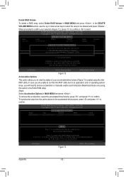
...cache device to the Accelerated Disk/Volume Press 'r' to be deleted and press . When prompted to confirm your accelerated drive/volume (Figure 13) created using this option in the RAID ROM utility. Intel(R) Rapid Storage Technology - WARNING: ALL DISK DATA WILL BE DELETED. ... the array to remove the Disk/Volume Acceleration WARNING: IT IS RECOMMENDED THAT YOU PERFORM A SYNCHRONIZATION BEFORE REMOVING ACCELERATION [hi]-Select Figure 13 [ESC]- Option ROM - 10.6.0.1091 Copyright(C) 2003-11 Intel Corporation. Option ROM - 10.6.0.1091 Copyright(C) 2003-11 Intel Corporation. To...
...cache device to the Accelerated Disk/Volume Press 'r' to be deleted and press . When prompted to confirm your accelerated drive/volume (Figure 13) created using this option in the RAID ROM utility. Intel(R) Rapid Storage Technology - WARNING: ALL DISK DATA WILL BE DELETED. ... the array to remove the Disk/Volume Acceleration WARNING: IT IS RECOMMENDED THAT YOU PERFORM A SYNCHRONIZATION BEFORE REMOVING ACCELERATION [hi]-Select Figure 13 [ESC]- Option ROM - 10.6.0.1091 Copyright(C) 2003-11 Intel Corporation. Option ROM - 10.6.0.1091 Copyright(C) 2003-11 Intel Corporation. To...