User Manual
Page 4
... 5: Install I/O Peripherals Cables 12 Step 5-1: I/O Back Panel Introduction 12 Step 5-2 : Connectors Introduction 13 Chapter 2 BIOS Setup 21 The Main Menu (For example: BIOS Ver. : F4c 21 Standard CMOSFeatures ...23 Advanced BIOS Features ...25 IntegratedPeripherals ...26 PowerManagementSetup ...28 PnP/PCIConfigurations ...30 PCI Health Status ...31 Frequency/VoltageControl ...32 LoadFail-Safe Defaults ...34 LoadOptimized Defaults ...34 SetSupervisor/User Password ...35 Save & Exit Setup ...36 Exit Without Saving ...36 Chapter 3 Install Drivers 37 7VT600-RZ Series Motherboard...
... 5: Install I/O Peripherals Cables 12 Step 5-1: I/O Back Panel Introduction 12 Step 5-2 : Connectors Introduction 13 Chapter 2 BIOS Setup 21 The Main Menu (For example: BIOS Ver. : F4c 21 Standard CMOSFeatures ...23 Advanced BIOS Features ...25 IntegratedPeripherals ...26 PowerManagementSetup ...28 PnP/PCIConfigurations ...30 PCI Health Status ...31 Frequency/VoltageControl ...32 LoadFail-Safe Defaults ...34 LoadOptimized Defaults ...34 SetSupervisor/User Password ...35 Save & Exit Setup ...36 Exit Without Saving ...36 Chapter 3 Install Drivers 37 7VT600-RZ Series Motherboard...

User Manual
Page 5
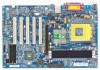
... s/w switch) - Licensed Award BIOS - Sourth Bridge: VIA VT8235 - 3 184-pin DDR sockets - Line In / 2 rear speaker(by s/w switch) - System voltage detect - CPU/System fan fail warning - PS/2 Keyboard interface and PS/2 Mouse interface - Built in VIA VT8235 Chipset - CPU/System Fan Revolution detect - Supports DDR DRAM PC2100/PC2700/PC3200 - Realtek ALC655 CODEC - IT8705 - Supports 1.4GHz and faster - CD In / AUX In / Game Port - Therm al shutdown function " * " Support 7VT600-RZ only. - 5 - Floppy port supports...
... s/w switch) - Licensed Award BIOS - Sourth Bridge: VIA VT8235 - 3 184-pin DDR sockets - Line In / 2 rear speaker(by s/w switch) - System voltage detect - CPU/System fan fail warning - PS/2 Keyboard interface and PS/2 Mouse interface - Built in VIA VT8235 Chipset - CPU/System Fan Revolution detect - Supports DDR DRAM PC2100/PC2700/PC3200 - Realtek ALC655 CODEC - IT8705 - Supports 1.4GHz and faster - CD In / AUX In / Game Port - Therm al shutdown function " * " Support 7VT600-RZ only. - 5 - Floppy port supports...
User Manual
Page 6
... g Form Factor - PS/2 M ouse power on by double click - Exter n al M odem wake up from S3 - USB KB/M ouse wake up - etc. 7VT600-RZ Series Motherboard - 6 - PS/2 Keyboard power on by password, - Supports EasyTune 4 - STR(Suspend-To-RAM) - Poly fuse for keyboard over the CPU's specification because these specific bus frequencies properly will depend on yourhardware configurations,including CPU, Memory,Cards... Supports @BIOS - Whether your processor's specifications. Over Clock (CPU/AGP/DDR/PCI) by BIOS - AC Recovery - Please set th e system b us freque...
... g Form Factor - PS/2 M ouse power on by double click - Exter n al M odem wake up from S3 - USB KB/M ouse wake up - etc. 7VT600-RZ Series Motherboard - 6 - PS/2 Keyboard power on by password, - Supports EasyTune 4 - STR(Suspend-To-RAM) - Poly fuse for keyboard over the CPU's specification because these specific bus frequencies properly will depend on yourhardware configurations,including CPU, Memory,Cards... Supports @BIOS - Whether your processor's specifications. Over Clock (CPU/AGP/DDR/PCI) by BIOS - AC Recovery - Please set th e system b us freque...
User Manual
Page 10
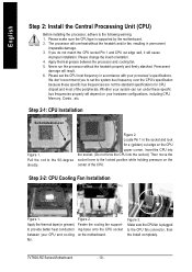
... Central Processing Unit (CPU) Before installing the processor, adhere to the CPU fan connector, than the install completely. 7VT600-RZ Series Motherboard - 10 - Make sure the CPU fan is supported by the motherboard. 2. If you to provide better heat conduction between the processor and cooling fan. 5. Step 2-2: CPU Cooling Fan Installation Figure 1. The processor will result. 6. Locate Pin 1 in permanent irreparable damage. 3. Never run under these specific bus frequencies are not the standard specifications for a (golden) cut...
... Central Processing Unit (CPU) Before installing the processor, adhere to the CPU fan connector, than the install completely. 7VT600-RZ Series Motherboard - 10 - Make sure the CPU fan is supported by the motherboard. 2. If you to provide better heat conduction between the processor and cooling fan. 5. Step 2-2: CPU Cooling Fan Installation Figure 1. The processor will result. 6. Locate Pin 1 in permanent irreparable damage. 3. Never run under these specific bus frequencies are not the standard specifications for a (golden) cut...

User Manual
Page 16
... IDE H a rd D i sk Acti ve LED Pin 1:LED anode(+) Pin 2:LED cathode(-) Pin1: VCC(+) Pin2- If you want to the manufacturer's instructions. Plug the power cord and turn on the computer. - 16 - Pin 3:NC Pin4:Data(-) Open:NormalOperation Close:ResetHardware System Open:NormalOperation Close:Power On/Off Pin 1:LED anode(+) Pin 2:LED cathode(-) NC 8) BATTERY (Battery) + 7VT600-RZ Series Motherboard CAUT ION Danger of your chassis front panel to the F_PANEL connector according to the pin...
... IDE H a rd D i sk Acti ve LED Pin 1:LED anode(+) Pin 2:LED cathode(-) Pin1: VCC(+) Pin2- If you want to the manufacturer's instructions. Plug the power cord and turn on the computer. - 16 - Pin 3:NC Pin4:Data(-) Open:NormalOperation Close:ResetHardware System Open:NormalOperation Close:Power On/Off Pin 1:LED anode(+) Pin 2:LED cathode(-) NC 8) BATTERY (Battery) + 7VT600-RZ Series Motherboard CAUT ION Danger of your chassis front panel to the F_PANEL connector according to the pin...

User Manual
Page 17
... sam e as the pin assigm ent on the M B header. To find out if the chassis you are buying support front audio connector, please contact your dealer. English 9) F_AUDIO (Front Audio Connector) If you want to play sound. 10 9 2 1 Pin No. 1 2 3 4 5 6 7 8 9 10 Definition MIC GND REF Power FrontAudio (R) RearAudio (R) Reserved No Pin FrontAudio (L) RearAudio (L) 10) SUR_CEN (Surround Center Connector) Please contact your chassis must remove 5-6, 9-10 Jumper.
... sam e as the pin assigm ent on the M B header. To find out if the chassis you are buying support front audio connector, please contact your dealer. English 9) F_AUDIO (Front Audio Connector) If you want to play sound. 10 9 2 1 Pin No. 1 2 3 4 5 6 7 8 9 10 Definition MIC GND REF Power FrontAudio (R) RearAudio (R) Reserved No Pin FrontAudio (L) RearAudio (L) 10) SUR_CEN (Surround Center Connector) Please contact your chassis must remove 5-6, 9-10 Jumper.

User Manual
Page 18
... optional SPDIF cable, please contact your device has digital output function. English 12) AUX_IN ( AUX In Connector) Connect other device (such as PCI TV Tunner audio out)to an external Dolby Digital Decoder. Use SPDIF in feature only when your local dealer. 26 15 Pin No. 1 2 3 4 5 6 Definition VCC No Pin SPDIF SPDIFI GND GND 7VT600-RZ Series Motherboard - 18 - Pin No. Check the pin assignment carefully while you connect the SPDIF cable, incorrect connection...
... optional SPDIF cable, please contact your device has digital output function. English 12) AUX_IN ( AUX In Connector) Connect other device (such as PCI TV Tunner audio out)to an external Dolby Digital Decoder. Use SPDIF in feature only when your local dealer. 26 15 Pin No. 1 2 3 4 5 6 Definition VCC No Pin SPDIF SPDIFI GND GND 7VT600-RZ Series Motherboard - 18 - Pin No. Check the pin assignment carefully while you connect the SPDIF cable, incorrect connection...

User Manual
Page 19
... 16 No Pin 16) CI (Chassis Intrusion, Case Open) This 2-pin connector allows your nearest dealer for optional gam e cables. Check the pin assignment while you connect the F_USB cable, incorrect connection between the cable and connector will make the device unable to enable or disable the "case open" item in BIOS if the system case begin rem ove. Definition 1 Signal 1 2 GND - 19 - Please contact your system to work or...
... 16 No Pin 16) CI (Chassis Intrusion, Case Open) This 2-pin connector allows your nearest dealer for optional gam e cables. Check the pin assignment while you connect the F_USB cable, incorrect connection between the cable and connector will make the device unable to enable or disable the "case open" item in BIOS if the system case begin rem ove. Definition 1 Signal 1 2 GND - 19 - Please contact your system to work or...
User Manual
Page 22
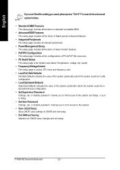
... Password Change, set , or disable password. English Ifyoucan'tfindthe setting you to lim it access to the system. • Save & Exit Setup Save CMOS value settings to CM OS and exit setup. • Exit Without Saving Abandon all the configurations of PCI & PnP ISA resources. • PC Health Status This setup page is the System auto detect Temperature, voltage, fan, speed. • Frequency/VoltageControl This setup page is control CPU clock and frequency ratio. • Load...
... Password Change, set , or disable password. English Ifyoucan'tfindthe setting you to lim it access to the system. • Save & Exit Setup Save CMOS value settings to CM OS and exit setup. • Exit Without Saving Abandon all the configurations of PCI & PnP ISA resources. • PC Health Status This setup page is the System auto detect Temperature, voltage, fan, speed. • Frequency/VoltageControl This setup page is control CPU clock and frequency ratio. • Load...

User Manual
Page 23
... HDD type. Drive A Drive B Floppy 3 Mode Suport Holt On Base Memory Extended Memory Total Memory higf : Move Enter: Select F5: Previous Values [1.44M, 3.5"] [ No ne ] [D is calculated base on the hard disk. Auto type which the disk driver changes the write current. 8Landing Zone The cylinder number that has been installed in the documentation form your drive must match with the drive table. BIOS Setup English Standard CMOS Features CMOS Setup Utility-Copyright (C) 1984-2004 Award Software Standard CMOS...
... HDD type. Drive A Drive B Floppy 3 Mode Suport Holt On Base Memory Extended Memory Total Memory higf : Move Enter: Select F5: Previous Values [1.44M, 3.5"] [ No ne ] [D is calculated base on the hard disk. Auto type which the disk driver changes the write current. 8Landing Zone The cylinder number that has been installed in the documentation form your drive must match with the drive table. BIOS Setup English Standard CMOS Features CMOS Setup Utility-Copyright (C) 1984-2004 Award Software Standard CMOS...
User Manual
Page 25
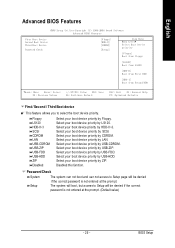
Select your boot device priority by LAN. Select your boot device priority by USB-HDD. Select your boot device priority by CDROM. Select your boot device priority by USB-ZIP. The system will boot, but access to Setup will be denied if the correct password is not entered at the prom pt. (Default value) - 25 - English Advanced BIOS Features CMOS Setup Utility-Copyright (C) 1984-2004 Award Software Advanced BIOS Features First Boot Device Second Boot Device Third Boot Device Password Check [F lopp y] [H DD...
Select your boot device priority by LAN. Select your boot device priority by USB-HDD. Select your boot device priority by CDROM. Select your boot device priority by USB-ZIP. The system will boot, but access to Setup will be denied if the correct password is not entered at the prom pt. (Default value) - 25 - English Advanced BIOS Features CMOS Setup Utility-Copyright (C) 1984-2004 Award Software Advanced BIOS Features First Boot Device Second Boot Device Third Boot Device Password Check [F lopp y] [H DD...
User Manual
Page 26
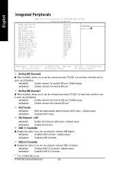
... Audio 8Enab led 8Disa bled BIOS will automatically detect onboard AC97 Audio. (Default value) Disabled AC97 Audio. " * " For 7VT600-RZ-C only. 7VT600-RZ Series Motherboard - 26 - English Integrated Peripherals CMOS Setup Utility-Copyright (C) 1984-2003 Award Software Integrated Peripherals OnChip IDE Channel0 OnChip IDE Channel1 AC97 Audio VIA Onboard LAN * USB 1.1 Controller USB 2.0 Controller USB Keyboard Support USB Mouse Support VIA LAN Boot ROM * Onboard Serial Port 1 Onboard Serial Port 2 Onboard Parallel Port UART Mode Select Parallel Port Mode Game Port Address Midi Port Address...
... Audio 8Enab led 8Disa bled BIOS will automatically detect onboard AC97 Audio. (Default value) Disabled AC97 Audio. " * " For 7VT600-RZ-C only. 7VT600-RZ Series Motherboard - 26 - English Integrated Peripherals CMOS Setup Utility-Copyright (C) 1984-2003 Award Software Integrated Peripherals OnChip IDE Channel0 OnChip IDE Channel1 AC97 Audio VIA Onboard LAN * USB 1.1 Controller USB 2.0 Controller USB Keyboard Support USB Mouse Support VIA LAN Boot ROM * Onboard Serial Port 1 Onboard Serial Port 2 Onboard Parallel Port UART Mode Select Parallel Port Mode Game Port Address Midi Port Address...

User Manual
Page 27
... the boot ROM of param eters if the parallel port uses the onboard I /O chip as Smart Card interface. Enable onboard Serial port 1 and address is 3E8,Using IRQ4. F OnBoard Parallel port MThis feature allows you to IrDA M ode. Disable onboard Serial port 2. English F USB Keyboard Support MWhen a USB keyboard is 3F8,Using IRQ4. F Onboard Serial Port 1 8Auto BIOS will autom atically setup the port 2 address. 83F 8/ IR Q4 82F 8/ IR Q3 Enable onboard Serial port 2 and address is installed, please set of the onboard LAN chip. 8Disa bled Disable this function. (Default...
... the boot ROM of param eters if the parallel port uses the onboard I /O chip as Smart Card interface. Enable onboard Serial port 1 and address is 3E8,Using IRQ4. F OnBoard Parallel port MThis feature allows you to IrDA M ode. Disable onboard Serial port 2. English F USB Keyboard Support MWhen a USB keyboard is 3F8,Using IRQ4. F Onboard Serial Port 1 8Auto BIOS will autom atically setup the port 2 address. 83F 8/ IR Q4 82F 8/ IR Q3 Enable onboard Serial port 2 and address is installed, please set of the onboard LAN chip. 8Disa bled Disable this function. (Default...

User Manual
Page 28
... Using Parallel port as Extended Capabilities Port using IRQ7. 8ECP+EPP Using Parallel port as ECP & EPP mode. English F Parallel Port Mode MThis feature allows you to 330. F Midi Port IRQ 85 Set 5 for M idi Port IRQ. 810 Set 10 for Midi Port IRQ.(Default value) Power Management Setup CMOS Setup Utility-Copyright (C) 1984-2003 Award Software Power Management Setup ACPI Suspend Type x USB Device Wake-Up From S3 Power LED in S1 state Soft-Off by PWRBTN AC Back Function Keyboard Power...
... Using Parallel port as Extended Capabilities Port using IRQ7. 8ECP+EPP Using Parallel port as ECP & EPP mode. English F Parallel Port Mode MThis feature allows you to 330. F Midi Port IRQ 85 Set 5 for M idi Port IRQ. 810 Set 10 for Midi Port IRQ.(Default value) Power Management Setup CMOS Setup Utility-Copyright (C) 1984-2003 Award Software Power Management Setup ACPI Suspend Type x USB Device Wake-Up From S3 Power LED in S1 state Soft-Off by PWRBTN AC Back Function Keyboard Power...
User Manual
Page 30
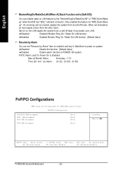
... to enabled and key in Data/time to power on system. 8Disa bled Disable this function. (Default Value) 8Enab led Enable alarm function to [Soft-Off]) You can enable wake on LAN feature by "PME Event Wake up " when the M /B has "WOL" onboard connector. Date (of Month) Alarm : Everyday, 1~31 Time (hh: m m: ss) Alarm : (0~23) : (0~59) : (0~59) PnP/PCI Configurations CMOS Setup Utility-Copyright (C) 1984-2003 Award Software PnP/PCI Configurations PCI1/PCI5...
... to enabled and key in Data/time to power on system. 8Disa bled Disable this function. (Default Value) 8Enab led Enable alarm function to [Soft-Off]) You can enable wake on LAN feature by "PME Event Wake up " when the M /B has "WOL" onboard connector. Date (of Month) Alarm : Everyday, 1~31 Time (hh: m m: ss) Alarm : (0~23) : (0~59) : (0~59) PnP/PCI Configurations CMOS Setup Utility-Copyright (C) 1984-2003 Award Software PnP/PCI Configurations PCI1/PCI5...

User Manual
Page 31
... 8Auto 83,4, 5,7,9. ,10,11 ,12,14 ,15 Auto assign IRQ to PCI 2. (Default value) Set 3,4,5,7,9,10,11,12,14,15 to PCI4. PCI Health Status CMOS Setup Utility-Copyright (C) 1984-2003 Award Software PC Health Status Reset Case Open Status Case Opened Vco re DDR Vtt +3. 3V +5 V +1 2V 5V SB Current System Temperature Current CPU Temperature Current CPU FAN Speed Current SYSTEM FAN Speed [D is ab le d] No 1 .8 10 V 1 .2 48 V 3 .2 80...
... 8Auto 83,4, 5,7,9. ,10,11 ,12,14 ,15 Auto assign IRQ to PCI 2. (Default value) Set 3,4,5,7,9,10,11,12,14,15 to PCI4. PCI Health Status CMOS Setup Utility-Copyright (C) 1984-2003 Award Software PC Health Status Reset Case Open Status Case Opened Vco re DDR Vtt +3. 3V +5 V +1 2V 5V SB Current System Temperature Current CPU Temperature Current CPU FAN Speed Current SYSTEM FAN Speed [D is ab le d] No 1 .8 10 V 1 .2 48 V 3 .2 80...

User Manual
Page 32
...Enabled. 7VT600-RZ Series Motherboard - 32 - F CurrentSystem Temperature (°C) Detect System Tem p. automatically. autom atically. F Current CPU FAN / SYSTEM FAN Speed (RPM) Detect Fan speed status automatically. F Fan Fail Warning (CPU / SYSTEM) 8Disa bled 8Enab led Don't m onitor current fan speed. (Default value) Alarm when stops. Frequency/Voltage Control CMOS Setup Utility-Copyright (C) 1984-2003 Award Software Frequency/Voltage Control Spread Spectrum Modulated CPU Host Clock Control øCPU Host Frequency(MHz) øPCI/AGP Frequency(MHz) DRAM Clock(MHz) CPU...
...Enabled. 7VT600-RZ Series Motherboard - 32 - F CurrentSystem Temperature (°C) Detect System Tem p. automatically. autom atically. F Current CPU FAN / SYSTEM FAN Speed (RPM) Detect Fan speed status automatically. F Fan Fail Warning (CPU / SYSTEM) 8Disa bled 8Enab led Don't m onitor current fan speed. (Default value) Alarm when stops. Frequency/Voltage Control CMOS Setup Utility-Copyright (C) 1984-2003 Award Software Frequency/Voltage Control Spread Spectrum Modulated CPU Host Clock Control øCPU Host Frequency(MHz) øPCI/AGP Frequency(MHz) DRAM Clock(MHz) CPU...

User Manual
Page 33
... values depend on CPU Host Frequency(Mhz) . BIOS Setup When tim e out occur, system will reset and run at CPU default Host clock at next boot. 8Disable Disable CPU Host Clock Control.(Default value) 8Enable Enable CPU Host Clock Control. For power End-User use DDR266 DRAM module, please set DRAM Clock according to DRAM m odule when enable this feature. 8Auto Supply voltage as DRAM module reguired. (Default value) 8+0.1V ~ +0.3V Set DIMM voltage from 1.6V~1.8V. FCPU OverVoltage Control Increase CPU voltage m ay get stable...
... values depend on CPU Host Frequency(Mhz) . BIOS Setup When tim e out occur, system will reset and run at CPU default Host clock at next boot. 8Disable Disable CPU Host Clock Control.(Default value) 8Enable Enable CPU Host Clock Control. For power End-User use DDR266 DRAM module, please set DRAM Clock according to DRAM m odule when enable this feature. 8Auto Supply voltage as DRAM module reguired. (Default value) 8+0.1V ~ +0.3V Set DIMM voltage from 1.6V~1.8V. FCPU OverVoltage Control Increase CPU voltage m ay get stable...
User Manual
Page 35
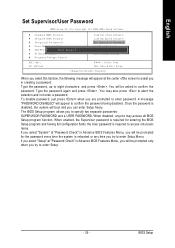
... Setup Utility-Copyright (C) 1984-2004 Award Software } Standard CMOS Features } Advanced BIOS Features } Integrated Peripherals } Power Management Setup } PnP/PCI ConfiguratEinotnesr Password: } PC Health Status } Frequency/Voltage Control Load Fail-Safe Defaults Load Optimized Defaults Set Supervisor Password Set User Password Save & Exit Setup Exit Without Saving ESC: Quit F8: Q-Flash higf : Select Item F10: Save & Exit Setup Change/Set/Disable Password When you select this function, the following message will boot and you can enter Setup freely. Type the password, up to access...
... Setup Utility-Copyright (C) 1984-2004 Award Software } Standard CMOS Features } Advanced BIOS Features } Integrated Peripherals } Power Management Setup } PnP/PCI ConfiguratEinotnesr Password: } PC Health Status } Frequency/Voltage Control Load Fail-Safe Defaults Load Optimized Defaults Set Supervisor Password Set User Password Save & Exit Setup Exit Without Saving ESC: Quit F8: Q-Flash higf : Select Item F10: Save & Exit Setup Change/Set/Disable Password When you select this function, the following message will boot and you can enter Setup freely. Type the password, up to access...

User Manual
Page 36
... Item F10: Save & Exit Setup Abandon all Data Type "Y" will return to Setup Utility. 7VT600-RZ Series Motherboard - 36 - English Save & Exit Setup CMOS Setup Utility-Copyright (C) 1984-2004 Award Software } Standard CMOS Features Load Fail-Safe Defaults } Advanced BIOS Features Load Optimized Defaults } Integrated Peripherals Set Supervisor Password } Power Management Setup Set User Password } PnP/PCI Configurations Save to CMOS and EXITSa(vYe/N&)?ExYit Setup } PC Health Status Exit Without Saving } Frequency/Voltage Control ESC: Quit F8: Q-Flash higf : Select Item F10...
... Item F10: Save & Exit Setup Abandon all Data Type "Y" will return to Setup Utility. 7VT600-RZ Series Motherboard - 36 - English Save & Exit Setup CMOS Setup Utility-Copyright (C) 1984-2004 Award Software } Standard CMOS Features Load Fail-Safe Defaults } Advanced BIOS Features Load Optimized Defaults } Integrated Peripherals Set Supervisor Password } Power Management Setup Set User Password } PnP/PCI Configurations Save to CMOS and EXITSa(vYe/N&)?ExYit Setup } PC Health Status Exit Without Saving } Frequency/Voltage Control ESC: Quit F8: Q-Flash higf : Select Item F10...


