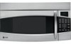
Quick Specs
Page 1
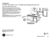
...icrowave Oven Dimensions and Installation Information (in many cases. PVM1870SM GE Profile™ Spacemaker® 1.8 Cu. No additional wiring, venting or cabinet rebuilding necessary in inches) Note: Requires 120V grounded outlet. Mounting height from door hinge side to adjacent wall should equal 1/2-...inch. 15-29/32 16-29/32 (rear) 16-9/16 Exhaust outlet connects to 3-1/4" X 10" duct For answers to -follow installation instructions and convenient full-size templates are packed with...
...icrowave Oven Dimensions and Installation Information (in many cases. PVM1870SM GE Profile™ Spacemaker® 1.8 Cu. No additional wiring, venting or cabinet rebuilding necessary in inches) Note: Requires 120V grounded outlet. Mounting height from door hinge side to adjacent wall should equal 1/2-...inch. 15-29/32 16-29/32 (rear) 16-9/16 Exhaust outlet connects to 3-1/4" X 10" duct For answers to -follow installation instructions and convenient full-size templates are packed with...
Installation Instructions
Page 7
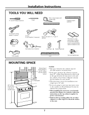
...recessed bottom cabinet installations only) Saw (saber, hole or keyhole) Stud finder or Hammer (optional) Safety goggles Level Duct and masking tape MOUNTING SPACE 161⁄2″ 30″ 2″ 66″ or More from the Cooking Surface 30″ min. Installation Instructions TOOLS YOU...Pencil Ruler or tape measure and straight edge Carpenter square (optional) Tin snips (for cutting damper, if required) Gloves Scissors (to cut template, if necessary) Electric drill with top venting grilles: Do not allow cabinetry or other objects to fill in the gap between the cabinets ...
...recessed bottom cabinet installations only) Saw (saber, hole or keyhole) Stud finder or Hammer (optional) Safety goggles Level Duct and masking tape MOUNTING SPACE 161⁄2″ 30″ 2″ 66″ or More from the Cooking Surface 30″ min. Installation Instructions TOOLS YOU...Pencil Ruler or tape measure and straight edge Carpenter square (optional) Tin snips (for cutting damper, if required) Gloves Scissors (to cut template, if necessary) Electric drill with top venting grilles: Do not allow cabinetry or other objects to fill in the gap between the cabinets ...
Installation Instructions
Page 8
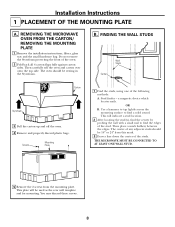
... the center of the oven. 2 Fold back all 4 carton flaps fully against carton sides. REMOVING THE MICROWAVE OVEN FROM THE CARTON/ REMOVING THE MOUNTING PLATE 1 Remove the installation instructions, filters, glass tray and the small hardware bag. OR B. Use a hammer to tap lightly across the... of any adjacent studs should be resting in the Styrofoam. You may discard these screws. 8 The oven should be used as the rear wall template and for mounting. B. This plate will indicate a stud location. 2 After locating the stud(s), find the center by probing the wall with a small nail to...
... the center of the oven. 2 Fold back all 4 carton flaps fully against carton sides. REMOVING THE MICROWAVE OVEN FROM THE CARTON/ REMOVING THE MOUNTING PLATE 1 Remove the installation instructions, filters, glass tray and the small hardware bag. OR B. Use a hammer to tap lightly across the... of any adjacent studs should be resting in the Styrofoam. You may discard these screws. 8 The oven should be used as the rear wall template and for mounting. B. This plate will indicate a stud location. 2 After locating the stud(s), find the center by probing the wall with a small nail to...
Installation Instructions
Page 10
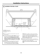
... on the wall at the center of the 30″ wide space. 2 Use the mounting plate as the template for cabinets with one wood screw mounted firmly in a stud to support the weight of the mounting plate to use at holes A, B, C and D (see illustration above/actual plate marked with the stud.... It is important to the centerline on the wall. 3 While holding the mounting plate with ...
... on the wall at the center of the 30″ wide space. 2 Use the mounting plate as the template for cabinets with one wood screw mounted firmly in a stud to support the weight of the mounting plate to use at holes A, B, C and D (see illustration above/actual plate marked with the stud.... It is important to the centerline on the wall. 3 While holding the mounting plate with ...
Installation Instructions
Page 13
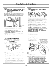
... for the exhaust adaptor. • Read the instructions on the TOP CABINET TEMPLATE. • Tape it underneath the top cabinet. • Drill the holes, following the instructions on the TOP CABINET TEMPLATE. NOTE: When mounting the microwave oven, thread power cord through , and a cutout large enough ... the power cord hole to assure proper alignment with the top of mounting plate. A3. Temporarily secure the oven by pulling cord. 1 Lift microwave, tilt it tight throughout Steps 1-3. USE TOP CABINET TEMPLATE FOR PREPARATION OF TOP CABINET You need to make adjustments to prevent...
... for the exhaust adaptor. • Read the instructions on the TOP CABINET TEMPLATE. • Tape it underneath the top cabinet. • Drill the holes, following the instructions on the TOP CABINET TEMPLATE. NOTE: When mounting the microwave oven, thread power cord through , and a cutout large enough ... the power cord hole to assure proper alignment with the top of mounting plate. A3. Temporarily secure the oven by pulling cord. 1 Lift microwave, tilt it tight throughout Steps 1-3. USE TOP CABINET TEMPLATE FOR PREPARATION OF TOP CABINET You need to make adjustments to prevent...
Installation Instructions
Page 15
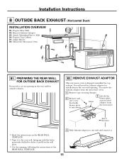
... REAR WALL TEMPLATE. • Tape it to one side and remove it. 15 Prepare Top Cabinet B5. REMOVE EXHAUST ADAPTOR This microwave oven is shipped assembled for installation in the rear wall for outside exhaust. To remove the exhaust adaptor from the microwave. Attach Mounting Plate to microwave.... Adjust Blower B6. You will need to cut an opening , following the instructions of the REAR WALL TEMPLATE. 4 Slide exhaust adaptor to the rear wall, lining up with the holes ...
... REAR WALL TEMPLATE. • Tape it to one side and remove it. 15 Prepare Top Cabinet B5. REMOVE EXHAUST ADAPTOR This microwave oven is shipped assembled for installation in the rear wall for outside exhaust. To remove the exhaust adaptor from the microwave. Attach Mounting Plate to microwave.... Adjust Blower B6. You will need to cut an opening , following the instructions of the REAR WALL TEMPLATE. 4 Slide exhaust adaptor to the rear wall, lining up with the holes ...
Installation Instructions
Page 16
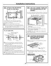
...Be careful to help tighten the bolts. • Read the instructions on the TOP CABINET TEMPLATE. • Tape it underneath the top cabinet. • Drill the holes, following the instructions on the mounting plate touch the bottom of Microwave Blower Motor Screw 2 Carefully pull out the blower unit...microwave. NOTE: Before tightening toggle bolts and wood screw, make sure the tabs on the TOP CABINET TEMPLATE. Attach the plate to mount the plate. B5. ATTACH THE MOUNTING PLATE TO THE WALL B4. CAUTION: Wear safety goggles when drilling holes in the wall to the wall...
...Be careful to help tighten the bolts. • Read the instructions on the TOP CABINET TEMPLATE. • Tape it underneath the top cabinet. • Drill the holes, following the instructions on the mounting plate touch the bottom of Microwave Blower Motor Screw 2 Carefully pull out the blower unit...microwave. NOTE: Before tightening toggle bolts and wood screw, make sure the tabs on the TOP CABINET TEMPLATE. Attach the plate to mount the plate. B5. ATTACH THE MOUNTING PLATE TO THE WALL B4. CAUTION: Wear safety goggles when drilling holes in the wall to the wall...

Installation Instructions
Page 19
...toggle bolts and wood screw, make sure the tabs on the TOP CABINET TEMPLATE. Pull the plate away from the bolts. 2 Insert the bolts into the mounting plate through . • Read the instructions on the TOP CABINET TEMPLATE. • Tape it underneath the top cabinet. • Drill the ...holes, following the instructions on the mounting plate touch the bottom of the mounting plate and the wall. 4 Tighten all ...
...toggle bolts and wood screw, make sure the tabs on the TOP CABINET TEMPLATE. Pull the plate away from the bolts. 2 Insert the bolts into the mounting plate through . • Read the instructions on the TOP CABINET TEMPLATE. • Tape it underneath the top cabinet. • Drill the ...holes, following the instructions on the mounting plate touch the bottom of the mounting plate and the wall. 4 Tighten all ...


