
Installation Instructions
Page 6
... exhaust vent. • Provide an opening with the NATIONAL FUEL GAS CODE, ANSI Z223. of duct to the MANUFACTURED HOME CONSTRUCTION & SAFETY STANDARD, TITLE 24, PART 32-80 or, when such standard is highly recommended (see illustrations below). Allow 2" of open area equally distributed. • The closet should not exceed 8 feet...
... exhaust vent. • Provide an opening with the NATIONAL FUEL GAS CODE, ANSI Z223. of duct to the MANUFACTURED HOME CONSTRUCTION & SAFETY STANDARD, TITLE 24, PART 32-80 or, when such standard is highly recommended (see illustrations below). Allow 2" of open area equally distributed. • The closet should not exceed 8 feet...
Installation Instructions
Page 8
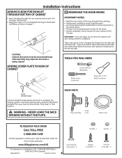
... or ThinBlade Screwdriver PLATE (KIT WE1M454) Connect standard metal elbows and ducts to protection under the terms of your warranty. DOOR PARTS Hinge Assembly Hinge Cover Plastic Cover TO REGISTER YOUR DRYER CALL TOLL-FREE 1-888-269-1192 Prompt registration confirms your local service provider...FOR EXHAUST THROUGH BOTTOM OF CABINET • Insert the elbow through before starting. • Handle parts carefully to avoid scratching paint. • Set screws down by their related parts to avoid using them back to the right side, follow these same instructions and reverse all the ...
... or ThinBlade Screwdriver PLATE (KIT WE1M454) Connect standard metal elbows and ducts to protection under the terms of your warranty. DOOR PARTS Hinge Assembly Hinge Cover Plastic Cover TO REGISTER YOUR DRYER CALL TOLL-FREE 1-888-269-1192 Prompt registration confirms your local service provider...FOR EXHAUST THROUGH BOTTOM OF CABINET • Insert the elbow through before starting. • Handle parts carefully to avoid scratching paint. • Set screws down by their related parts to avoid using them back to the right side, follow these same instructions and reverse all the ...
Installation Instructions
Page 9
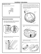
With the screws removed, turn the door over and separate the silver cover part of the door outlining the gasket and the 2 machine screws (#8) on the plastic cover. 9 Remove the 6 large tapping screws (#10) located around the perimeter of .... Loosen the top screw as shown by lifting and pulling as shown. Lay the door down on a soft protected flat surface so that the inner part faces upward (door resting on the plastic cover and separate the plastic cover from the door frame and set aside. 3.
With the screws removed, turn the door over and separate the silver cover part of the door outlining the gasket and the 2 machine screws (#8) on the plastic cover. 9 Remove the 6 large tapping screws (#10) located around the perimeter of .... Loosen the top screw as shown by lifting and pulling as shown. Lay the door down on a soft protected flat surface so that the inner part faces upward (door resting on the plastic cover and separate the plastic cover from the door frame and set aside. 3.
Installation Instructions
Page 10
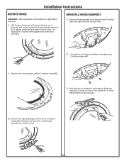
.... Place the hinge assembly in the opposite side of the hinge assembly. Remove the 2 nuts, washers, and the 2 machine screws (#8). 13. With the door frame part of the hinge (left or right) before removing. 8. Installation Instructions REMOVE HINGE IMPORTANT: Note the location of the door laid down on its side with...
.... Place the hinge assembly in the opposite side of the hinge assembly. Remove the 2 nuts, washers, and the 2 machine screws (#8). 13. With the door frame part of the hinge (left or right) before removing. 8. Installation Instructions REMOVE HINGE IMPORTANT: Note the location of the door laid down on its side with...
Installation Instructions
Page 11
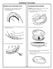
... in the door. 18. Installation Instructions REINSTALL NUTS AND HINGE COVER 14. Secure the hinge cover with the 4 tabs. 15. Make sure that the handle part of Door Outer Door Inner Door 19. Align the hinge cover holes with the holes in place with the 2 tapping screws (#8). Top of the outer...
... in the door. 18. Installation Instructions REINSTALL NUTS AND HINGE COVER 14. Secure the hinge cover with the 4 tabs. 15. Make sure that the handle part of Door Outer Door Inner Door 19. Align the hinge cover holes with the holes in place with the 2 tapping screws (#8). Top of the outer...

Installation Instructions
Page 12
... Screw Tighten All Screws MOVE STRIKE BRACKET 21. Switch the strike bracket and its cover to be installed on the opposite side. 22. For replacement parts and other flat tool, remove the 5 plastic screw caps located on the dryer where the door will be installed and install them on the dryer...
... Screw Tighten All Screws MOVE STRIKE BRACKET 21. Switch the strike bracket and its cover to be installed on the opposite side. 22. For replacement parts and other flat tool, remove the 5 plastic screw caps located on the dryer where the door will be installed and install them on the dryer...


