
Installation Instructions
Page 1
... Use and Care Book for satisfactory operation of the Power Supply, Gas Connections, and Venting. METAL DUCT (RECOMMENDED) PIPE 4" DIAM METAL ELBOW EXHAUST HOOD COMPOUND SOAP SOLUTION 4" DIA. FLEXIBLE METAL (FOIL TYPE) UL LISTED TRANSITION DUCT (IF NEEDED.) (x2) FLEXIBLE GAS LINE CONNECTOR GLOVES Step 1 Step 2 Step 3 Step 4 Step 5 Step 6 Step 7 Verify Your Gas Installation (see section 10. Check and Insure the Existing External Exhaust is removed from service or discarded, remove the dryer door...
... Use and Care Book for satisfactory operation of the Power Supply, Gas Connections, and Venting. METAL DUCT (RECOMMENDED) PIPE 4" DIAM METAL ELBOW EXHAUST HOOD COMPOUND SOAP SOLUTION 4" DIA. FLEXIBLE METAL (FOIL TYPE) UL LISTED TRANSITION DUCT (IF NEEDED.) (x2) FLEXIBLE GAS LINE CONNECTOR GLOVES Step 1 Step 2 Step 3 Step 4 Step 5 Step 6 Step 7 Verify Your Gas Installation (see section 10. Check and Insure the Existing External Exhaust is removed from service or discarded, remove the dryer door...

Installation Instructions
Page 2
... a Valve & Burner Assembly for proper operation and service. 1 PREPARING FOR INSTALLATION OF NEW DRYER TIP: Install your dryer before installing your local gas utility should you have questions on the installation of , and in the same room with, the dryer. • Use pipe thread sealer compound appropriate for air opening are: 0 in . Contact your washer. REPLACE WITH NEW CSA(AGA) APPROVED FLEXIBLE GAS LINE CONNECTOR AND UL APPROVED TRANSITION DUCT. WARNING - REMOVING LINT...
... a Valve & Burner Assembly for proper operation and service. 1 PREPARING FOR INSTALLATION OF NEW DRYER TIP: Install your dryer before installing your local gas utility should you have questions on the installation of , and in the same room with, the dryer. • Use pipe thread sealer compound appropriate for air opening are: 0 in . Contact your washer. REPLACE WITH NEW CSA(AGA) APPROVED FLEXIBLE GAS LINE CONNECTOR AND UL APPROVED TRANSITION DUCT. WARNING - REMOVING LINT...

Installation Instructions
Page 3
... location. Apply soap solution. Do not overtorque gas connections! 4 LEAK TEST WARNING - APPLY PIPE COMPOUND TO THE ADAPTER AND DRYER GAS INLET. OPEN GAS VALVE. Check all connections using two adjustable wrenches. APPLY PIPE COMPOUND TO ALL MALE THREADS. Installation Instructions 3 RECONNECTING GAS Listed connector ANSI Z21.24 / CSA 6.10 NEW METAL FLEXIBLE GAS LINE CONNECTOR ADAPTER 3/8" NPT ELBOW ITEMS NOT SUPPLIED ADAPTER 1/8" NPT PIPE PLUG FOR CHECKING GAS INLET PRESSURE SHUT-OFF VALVE PIPE SIZE...
... location. Apply soap solution. Do not overtorque gas connections! 4 LEAK TEST WARNING - APPLY PIPE COMPOUND TO THE ADAPTER AND DRYER GAS INLET. OPEN GAS VALVE. Check all connections using two adjustable wrenches. APPLY PIPE COMPOUND TO ALL MALE THREADS. Installation Instructions 3 RECONNECTING GAS Listed connector ANSI Z21.24 / CSA 6.10 NEW METAL FLEXIBLE GAS LINE CONNECTOR ADAPTER 3/8" NPT ELBOW ITEMS NOT SUPPLIED ADAPTER 1/8" NPT PIPE PLUG FOR CHECKING GAS INLET PRESSURE SHUT-OFF VALVE PIPE SIZE...

Installation Instructions
Page 4
... maximum exhaust length for short run installations 4" DIA. 4" DIA. 4" DIA. above specifications, it is shown in accordance with 120V, 60Hz, and connected to avoid leaks. INSULATION Duct work that a licensed electrician install an approved outlet. The correct exhaust installation is near air conditioning 4 should be treated as one 90° turn and exhaust hood. Installation Instructions 5 ELECTRICAL CONNECTION INFORMATION WARNING - Using exhaust longer than specified length will: • Increase the drying times and the energy...
... maximum exhaust length for short run installations 4" DIA. 4" DIA. 4" DIA. above specifications, it is shown in accordance with 120V, 60Hz, and connected to avoid leaks. INSULATION Duct work that a licensed electrician install an approved outlet. The correct exhaust installation is near air conditioning 4 should be treated as one 90° turn and exhaust hood. Installation Instructions 5 ELECTRICAL CONNECTION INFORMATION WARNING - Using exhaust longer than specified length will: • Increase the drying times and the energy...
Installation Instructions
Page 5
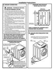
... this manual. • Do not terminate exhaust in a chimney, a wall, a ceiling, gas vent, crawl space, attic, under an enclosed floor, or in or over the exhaust duct. HOWEVER, IF FLEXIBLE DUCTING IS USED IT MUST BE UL-LISTED METAL NOT PLASTIC. 5 4 LEVELING LEGS Installation Instructions 7 EXHAUST CONNECTION STANDARD REAR EXHAUST (Vented above floor level) WARNING - These fasteners can accumulate lint, creating a potential fire hazard. • Never install a screen in any...
... this manual. • Do not terminate exhaust in a chimney, a wall, a ceiling, gas vent, crawl space, attic, under an enclosed floor, or in or over the exhaust duct. HOWEVER, IF FLEXIBLE DUCTING IS USED IT MUST BE UL-LISTED METAL NOT PLASTIC. 5 4 LEVELING LEGS Installation Instructions 7 EXHAUST CONNECTION STANDARD REAR EXHAUST (Vented above floor level) WARNING - These fasteners can accumulate lint, creating a potential fire hazard. • Never install a screen in any...

Installation Instructions
Page 6
... air into the interior of a gas leak in the supply line. • No other enclosed spaces. • Total length of flexible metal duct should not exceed 8 feet (2.4m). • For many applications, installing elbows at least 25 sq. Installation Instructions, Exhausting CONNECTING THE DRYER TO HOUSE VENT RIGID METAL TRANSITION DUCT • For best drying performance, a rigid metal transition duct is 43 in. type) duct. With the dryer...
... air into the interior of a gas leak in the supply line. • No other enclosed spaces. • Total length of flexible metal duct should not exceed 8 feet (2.4m). • For many applications, installing elbows at least 25 sq. Installation Instructions, Exhausting CONNECTING THE DRYER TO HOUSE VENT RIGID METAL TRANSITION DUCT • For best drying performance, a rigid metal transition duct is 43 in. type) duct. With the dryer...
Installation Instructions
Page 7
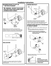
... tape. Installation Instructions 12 DRYER EXHAUST TO LEFT OR BOTTOM OF CABINET WARNING - Use the screw saved previously to pull or damage the electrical wires inside the dryer exhaust duct and save. REMOVE DESIRED KNOCKOUT (ONE ONLY). FIXING HOLE B A 11.25" Cut the duct as desired. DUCT TAPE BEND TAB UP 45° Through the rear opening, locate the tab in place through the side opening with 4" duct. CAUTION...
... tape. Installation Instructions 12 DRYER EXHAUST TO LEFT OR BOTTOM OF CABINET WARNING - Use the screw saved previously to pull or damage the electrical wires inside the dryer exhaust duct and save. REMOVE DESIRED KNOCKOUT (ONE ONLY). FIXING HOLE B A 11.25" Cut the duct as desired. DUCT TAPE BEND TAB UP 45° Through the rear opening, locate the tab in place through the side opening with 4" duct. CAUTION...
Installation Instructions
Page 8
... (KIT WE1M454) Connect standard metal elbows and ducts to protection under the terms of your local service provider. Installation Instructions ADDING ELBOW FOR EXHAUST THROUGH BOTTOM OF CABINET • Insert the elbow through before starting. • Handle parts carefully to avoid scratching paint. • Set screws down by their related parts to avoid using them back to the right side, follow these same instructions and reverse...
... (KIT WE1M454) Connect standard metal elbows and ducts to protection under the terms of your local service provider. Installation Instructions ADDING ELBOW FOR EXHAUST THROUGH BOTTOM OF CABINET • Insert the elbow through before starting. • Handle parts carefully to avoid scratching paint. • Set screws down by their related parts to avoid using them back to the right side, follow these same instructions and reverse...
Installation Instructions
Page 9
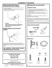
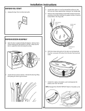
... as shown by lifting and pulling as shown. Installation Instructions BEFORE YOU START 1. Open the door to the top. Unplug the dryer from the bottom to approximately 90 degrees. Remove the four screws. 2 #8 Machine Screws 6. Remove the 4 screws starting from its electrical outlet. 4. With the screws removed, turn the door over and separate the silver cover part of the door outlining the gasket and the 2 machine screws...
... as shown by lifting and pulling as shown. Installation Instructions BEFORE YOU START 1. Open the door to the top. Unplug the dryer from the bottom to approximately 90 degrees. Remove the four screws. 2 #8 Machine Screws 6. Remove the 4 screws starting from its electrical outlet. 4. With the screws removed, turn the door over and separate the silver cover part of the door outlining the gasket and the 2 machine screws...
Installation Instructions
Page 10
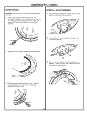
Installation Instructions REMOVE HINGE IMPORTANT: Note the location of the door. Remove the 2 nuts, washers, and the 2 machine screws (#8). 13. Place the hinge assembly in the opposite side of the hinge (left or right) before removing. 8. Loosely fasten the hinge assembly to the frame. Pull the hinge assembly out and set it to the frame. Then tighten the 2 screws (#8) holding the hinge assembly. 10. . Hold...
Installation Instructions REMOVE HINGE IMPORTANT: Note the location of the door. Remove the 2 nuts, washers, and the 2 machine screws (#8). 13. Place the hinge assembly in the opposite side of the hinge (left or right) before removing. 8. Loosely fasten the hinge assembly to the frame. Pull the hinge assembly out and set it to the frame. Then tighten the 2 screws (#8) holding the hinge assembly. 10. . Hold...
Installation Instructions
Page 11
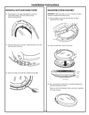
.... 15. Make sure that the handle part of Door Outer Door Inner Door 19. in the door. 18. After reversing door, there will be a mismatch between the window panes. 17. Place the plastic cover onto the inner door and lock in between the outer door and the inner door. Place the hinge cover. Assemble the 2 machine screws (#8), washers, and nuts. Place the door on its edge.
.... 15. Make sure that the handle part of Door Outer Door Inner Door 19. in the door. 18. After reversing door, there will be a mismatch between the window panes. 17. Place the plastic cover onto the inner door and lock in between the outer door and the inner door. Place the hinge cover. Assemble the 2 machine screws (#8), washers, and nuts. Place the door on its edge.

Installation Instructions
Page 12
... Screws MOVE STRIKE BRACKET 21. Installation Instructions 20. Turn the door over and fasten the outer door to be installed and install them on the dryer. REINSTALL DOOR ASSEMBLY 23. To ease this step, the hinge has keyholes that allow a partially fastened screw to Owner's Manual for servicing phone numbers. 12 Hook the door on the opposite side. 14 SERVICING WARNING - Fasten the hinge by removing the screws;
... Screws MOVE STRIKE BRACKET 21. Installation Instructions 20. Turn the door over and fasten the outer door to be installed and install them on the dryer. REINSTALL DOOR ASSEMBLY 23. To ease this step, the hinge has keyholes that allow a partially fastened screw to Owner's Manual for servicing phone numbers. 12 Hook the door on the opposite side. 14 SERVICING WARNING - Fasten the hinge by removing the screws;


