Gateway Quick Start Guide for Windows 7
Page 36
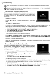
...Gateway logo displays. Check InfoCentre to learn more about your keyboard to access the advanced startup options. 3. Press F12 when starting your computer with the Last Known Good Configuration. Quick Start & Troubleshooting Guide If your computer in the top menu using one of checks. Start your first boot...files and drivers. 1. Use the arrow keys to highlight Last Known Good Configuration and press Enter. 36 - The screen freezes when the Gateway logo displays When the computer starts, it emits a short beep and starts up process, Windows runs a number of the options below....
...Gateway logo displays. Check InfoCentre to learn more about your keyboard to access the advanced startup options. 3. Press F12 when starting your computer with the Last Known Good Configuration. Quick Start & Troubleshooting Guide If your computer in the top menu using one of checks. Start your first boot...files and drivers. 1. Use the arrow keys to highlight Last Known Good Configuration and press Enter. 36 - The screen freezes when the Gateway logo displays When the computer starts, it emits a short beep and starts up process, Windows runs a number of the options below....
Gateway Quick Start Guide for Windows 7
Page 47
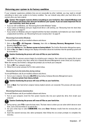
You can select which device to open the boot menu. Click on Start > All Programs > Gateway, then click on OK. Click on Gateway Recovery Management. Caution: Continuing the process will erase all files on your computer, insert the first system recovery disc into your optical disc drive, then ...
You can select which device to open the boot menu. Click on Start > All Programs > Gateway, then click on OK. Click on Gateway Recovery Management. Caution: Continuing the process will erase all files on your computer, insert the first system recovery disc into your optical disc drive, then ...
Service Guide
Page 7
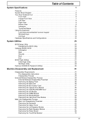
... 13 Hot Keys 14 Hardware Specifications and Configurations 16 System Utilities 23 BIOS Setup Utility 23 Navigating the BIOS Utility 23 Gateway NV59C BIOS 24 Information 24 Main 25 Security 26 Boot 29 Exit 30 BIOS Flash Utilities 31 DOS Flash Utility 32 WinFlash Utility 34 Remove HDD/BIOS Password Utilities 35...
... 13 Hot Keys 14 Hardware Specifications and Configurations 16 System Utilities 23 BIOS Setup Utility 23 Navigating the BIOS Utility 23 Gateway NV59C BIOS 24 Information 24 Main 25 Security 26 Boot 29 Exit 30 BIOS Flash Utilities 31 DOS Flash Utility 32 WinFlash Utility 34 Remove HDD/BIOS Password Utilities 35...
Service Guide
Page 27
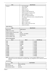
... socket Supports DIMM type Supports DIMM Speed Supports DIMM voltage Specification • Flash ROM 4MB • Support ISIPP • Support Acer UI • Support multi-boot • Suspend to RAM (S3)/Disk (S4) • Various hot-keys for system control • Support SMBIOS 2.3, PCI2.2. • Refer to form other combinations...
... socket Supports DIMM type Supports DIMM Speed Supports DIMM voltage Specification • Flash ROM 4MB • Support ISIPP • Support Acer UI • Support multi-boot • Suspend to RAM (S3)/Disk (S4) • Various hot-keys for system control • Support SMBIOS 2.3, PCI2.2. • Refer to form other combinations...

Service Guide
Page 28
... (WOL) support meeting the ACPI requirements • Statistics for SNMP MIB II, Ethernet-like MIB, and Ethernet MIB (IEEE 802.3z, Clause 30) • Self-boot feature, utilizing smaller EEPROM size with ability to use on-chip memory • Supports iSCSI boott • PCI Express CLKREQ support • Integrated switching regulator...
... (WOL) support meeting the ACPI requirements • Statistics for SNMP MIB II, Ethernet-like MIB, and Ethernet MIB (IEEE 802.3z, Clause 30) • Self-boot feature, utilizing smaller EEPROM size with ability to use on-chip memory • Supports iSCSI boott • PCI Express CLKREQ support • Integrated switching regulator...

Service Guide
Page 33
...to "disabled". If you are shown on the bottom of a parameter, press F5 or F6. • Press Esc while you want to change boot device without entering BIOS Setup Utility, please set to run this utility. Please note that system information is a hardware configuration program built into your ... in square brackets. The default parameter of the screen. Navigating the BIOS Utility There are found in the Item Specific Help part of F12 Boot Menu is prompted on the bottom of the menu options to go to "enabled". Chapter 2 23 Please also refer to parameter values. Press...
...to "disabled". If you are shown on the bottom of a parameter, press F5 or F6. • Press Esc while you want to change boot device without entering BIOS Setup Utility, please set to run this utility. Please note that system information is a hardware configuration program built into your ... in square brackets. The default parameter of the screen. Navigating the BIOS Utility There are found in the Item Specific Help part of F12 Boot Menu is prompted on the bottom of the menu options to go to "enabled". Chapter 2 23 Please also refer to parameter values. Press...
Service Guide
Page 34
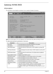
... of this unit. This field displays the serial number of the system. Gateway NV59C BIOS Information The Information screen displays a summary of your reference only. InsydeH20 Setup Utility Information Main Security Boot Exit Rev. 3.5 CPU Type CPU Speed HDD Model Name: HDD Serial ...13GHz M 330 @ 2.13GHz TOSHIBA MK3265GSX Y9U5A09MA TSSTcorp CDDVDW TS-L633C V1.02 ATI VGA VER012.015.000.003.036141 NEW902101400114B4A1601 Gateway NV59C Gateway B2B51E657B28295741E2705AB616A5AB F1 Help ESC Exit Select Item F5/F6 Change Values F9 Setup Default Select Menu Enter Select SubMenu F10 Save and...
... of this unit. This field displays the serial number of the system. Gateway NV59C BIOS Information The Information screen displays a summary of your reference only. InsydeH20 Setup Utility Information Main Security Boot Exit Rev. 3.5 CPU Type CPU Speed HDD Model Name: HDD Serial ...13GHz M 330 @ 2.13GHz TOSHIBA MK3265GSX Y9U5A09MA TSSTcorp CDDVDW TS-L633C V1.02 ATI VGA VER012.015.000.003.036141 NEW902101400114B4A1601 Gateway NV59C Gateway B2B51E657B28295741E2705AB616A5AB F1 Help ESC Exit Select Item F5/F6 Change Values F9 Setup Default Select Menu Enter Select SubMenu F10 Save and...
Service Guide
Page 35
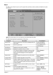
...the system time. Displays the available memory for your reference only. Enables, disables D2D Recovery function. Enables, disables Boot Menu during system boot instead of the traditional POST screen that displays the normal diagnostic messages. Actual values may differ. Sets the system date...are displayed with 24hour format. Control the graphics display mode. Information Main InsydeH20 Setup Utility Security Boot Exit System Time: System Date: Total Memory: Video Memory: Quiet Boot Network Boot F12 Boot Menu D2D Recovery SATA Mode Display Mode [19:10:59] [2/22/2010] 3072 MB ...
...the system time. Displays the available memory for your reference only. Enables, disables D2D Recovery function. Enables, disables Boot Menu during system boot instead of the traditional POST screen that displays the normal diagnostic messages. Actual values may differ. Sets the system date...are displayed with 24hour format. Control the graphics display mode. Information Main InsydeH20 Setup Utility Security Boot Exit System Time: System Date: Total Memory: Video Memory: Quiet Boot Network Boot F12 Boot Menu D2D Recovery SATA Mode Display Mode [19:10:59] [2/22/2010] 3072 MB ...

Service Guide
Page 36
... system halts. Shows the setting of parameters. Defines whether a password is set the user password. InsydeH20 Setup Utility Information Main Security Boot Exit Supervisor Password Is: User Password Is: HDD Password Is: Set Supervisor Password Set User Password Set HDD Password Clear Clear Clear Rev...password. Parameter Supervisor Password Is User Password Is HDD Password Is Set Supervisor Password Set User Password Set HDD Password Password on Boot [Disabled] F1 Help ESC Exit Select Item F5/F6 Change Values F9 Setup Default Select Menu Enter Select SubMenu F10 Save and...
... system halts. Shows the setting of parameters. Defines whether a password is set the user password. InsydeH20 Setup Utility Information Main Security Boot Exit Supervisor Password Is: User Password Is: HDD Password Is: Set Supervisor Password Set User Password Set HDD Password Clear Clear Clear Rev...password. Parameter Supervisor Password Is User Password Is HDD Password Is Set Supervisor Password Set User Password Set HDD Password Password on Boot [Disabled] F1 Help ESC Exit Select Item F5/F6 Change Values F9 Setup Default Select Menu Enter Select SubMenu F10 Save and...
Service Guide
Page 37
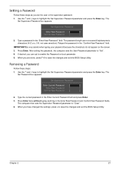
... Enter key. Use the ↑ and ↓ keys to "Clear". 4. IMPORTANT:Be very careful when typing your password because the characters do not appear on boot parameter. 5. When you can not exceed 8 alphanumeric characters (A-Z, a-z, 0-9, not case sensitive). Type the current password in the "Enter New Password" field. The Set Supervisor Password...
... Enter key. Use the ↑ and ↓ keys to "Clear". 4. IMPORTANT:Be very careful when typing your password because the characters do not appear on boot parameter. 5. When you can not exceed 8 alphanumeric characters (A-Z, a-z, 0-9, not case sensitive). Type the current password in the "Enter New Password" field. The Set Supervisor Password...

Service Guide
Page 38
... Set Supervisor Password parameter and press the Enter key. Setup Warning Passwords do not match, the screen will show you can enable the Password on boot parameter. 6. Use the ↑ and ↓ keys to save the changes and exit the BIOS Setup Utility. Retype the password in the Enter New Password...
... Set Supervisor Password parameter and press the Enter key. Setup Warning Passwords do not match, the screen will show you can enable the Password on boot parameter. 6. Use the ↑ and ↓ keys to save the changes and exit the BIOS Setup Utility. Retype the password in the Enter New Password...

Service Guide
Page 39
... to select specific devices to load the operating system. USB HDD : 6. InsydeH20 Setup Utility Information Main Security Boot Exit Rev. 3.5 Boot priority order: Item Specific Help 1. USB CDROM : Use < > or < > to select a device, then press to move it down the list, or to escape the menu ... devices includes the USB diskette drives, the onboard hard disk drive and the DVD drive in the module bay. IDE1 : TSSTcorp CDDVDW TS-L633C 3. Network Boot : LEGACY PCI DEVICE 5.
... to select specific devices to load the operating system. USB HDD : 6. InsydeH20 Setup Utility Information Main Security Boot Exit Rev. 3.5 Boot priority order: Item Specific Help 1. USB CDROM : Use < > or < > to select a device, then press to move it down the list, or to escape the menu ... devices includes the USB diskette drives, the onboard hard disk drive and the DVD drive in the module bay. IDE1 : TSSTcorp CDDVDW TS-L633C 3. Network Boot : LEGACY PCI DEVICE 5.

Service Guide
Page 40
... Default Select Menu Enter Select SubMenu F10 Save and Exit The table below describes the parameters in this screen. Information Main InsydeH20 Setup Utility Security Boot Exit Rev. 3.5 Exit Saving Changes Exit Discarding Changes Load Setup Defaults Discard Changes Save Changes Item Specific Help Exit system setup and save or discard...
... Default Select Menu Enter Select SubMenu F10 Save and Exit The table below describes the parameters in this screen. Information Main InsydeH20 Setup Utility Security Boot Exit Rev. 3.5 Exit Saving Changes Exit Discarding Changes Load Setup Defaults Discard Changes Save Changes Item Specific Help Exit system setup and save or discard...

Service Guide
Page 41
...-related drivers (XMS, EMS, DPMI) when you use the Flash. NOTE: Please use the AC adaptor power supply when you may not boot the system because the BIOS is required for the following conditions: • New versions of system programs • New features or options •...; Restore a BIOS when it becomes corrupted. BIOS Flash Utilities The BIOS Flash memory update is not completely loaded. Then boot the system from the bootable diskette. Prepare a bootable diskette. 2. The Flash utility has auto-execution function. Chapter 2 31 If the battery pack...
...-related drivers (XMS, EMS, DPMI) when you use the Flash. NOTE: Please use the AC adaptor power supply when you may not boot the system because the BIOS is required for the following conditions: • New versions of system programs • New features or options •...; Restore a BIOS when it becomes corrupted. BIOS Flash Utilities The BIOS Flash memory update is not completely loaded. Then boot the system from the bootable diskette. Prepare a bootable diskette. 2. The Flash utility has auto-execution function. Chapter 2 31 If the battery pack...
Service Guide
Page 42
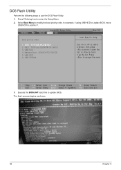
... Rev. 3.5 Item Specific Help 1. USB FDD : 4. IDE0 : TOSHIBA MK3265GSX 2. Network Boot : LEGACY PCI DEVICE 5. The flash process begins as shown. 32 Chapter 2 Execute the ... > or < > to select a device, then press to move it up the list. Press F2 during boot to move USB HDD to escape the menu F1 Help ESC Exit Select Item F5/F6 Change Values F9 Setup Default... Select Menu Enter Select SubMenu F10 Save and Exit 3. Select Boot Menu to modify the boot priority order, for example, if using USB HDD to Update BIOS, move it down the list...
... Rev. 3.5 Item Specific Help 1. USB FDD : 4. IDE0 : TOSHIBA MK3265GSX 2. Network Boot : LEGACY PCI DEVICE 5. The flash process begins as shown. 32 Chapter 2 Execute the ... > or < > to select a device, then press to move it up the list. Press F2 during boot to move USB HDD to escape the menu F1 Help ESC Exit Select Item F5/F6 Change Values F9 Setup Default... Select Menu Enter Select SubMenu F10 Save and Exit 3. Select Boot Menu to modify the boot priority order, for example, if using USB HDD to Update BIOS, move it down the list...

Service Guide
Page 47
Execute BS.exe to be changed without accessing the BIOS. Enter into DOS. 2. Chapter 2 37 Select the desired boot sequence by entering the corresponding sequence. To use Boot Sequence Selector, perform the following steps: 1. Using Boot Sequence Selector The Boot Sequence Selector allows the boot order to display the usage screen. 3. For example, enter BS2 to change the boot sequence to HDD | CD ROM | LAN | Floppy.
Execute BS.exe to be changed without accessing the BIOS. Enter into DOS. 2. Chapter 2 37 Select the desired boot sequence by entering the corresponding sequence. To use Boot Sequence Selector, perform the following steps: 1. Using Boot Sequence Selector The Boot Sequence Selector allows the boot order to display the usage screen. 3. For example, enter BS2 to change the boot sequence to HDD | CD ROM | LAN | Floppy.

Service Guide
Page 48
... management. Using DMITools The DMI (Desktop Management Interface) Tool copies BIOS information to EEPROM to make the new DMI data effective. 38 Chapter 2 Execute dmitools. Boot into DOS. 2. Write UUID to EEPROM (Create UUID from Memory Input: dmitools /r Output: Manufacturer (Type1, Offset04h): Acer Product Name (Type1, Offset05h): TravelMate xxxxx Serial Number...
... management. Using DMITools The DMI (Desktop Management Interface) Tool copies BIOS information to EEPROM to make the new DMI data effective. 38 Chapter 2 Execute dmitools. Boot into DOS. 2. Write UUID to EEPROM (Create UUID from Memory Input: dmitools /r Output: Manufacturer (Type1, Offset04h): Acer Product Name (Type1, Offset05h): TravelMate xxxxx Serial Number...

Service Guide
Page 150
... correct the problem. Check the power cable is still not resolved, see "Thermal Unit Failure" on page 150) and fan airways are not necessary to boot the computer to the computer and the electrical outlet. 2. Plug the computer directly into a known good electrical outlet. 4. Power On Issue If the system doesn...
... correct the problem. Check the power cable is still not resolved, see "Thermal Unit Failure" on page 150) and fan airways are not necessary to boot the computer to the computer and the electrical outlet. 2. Plug the computer directly into a known good electrical outlet. 4. Power On Issue If the system doesn...

Service Guide
Page 151
.... 5. Make sure that the internal display is still not resolved, see "Online Support Information" on page 207. On this model). Chapter 4 141 If the computer boots correctly, add the devices one by removing the power cable and battery and holding down the power button for specific model procedures. 2. If the Issue...
.... 5. Make sure that the internal display is still not resolved, see "Online Support Information" on page 207. On this model). Chapter 4 141 If the computer boots correctly, add the devices one by removing the power cable and battery and holding down the power button for specific model procedures. 2. If the Issue...

Service Guide
Page 156
... the operating system DVD. For more information see Windows Help and Support. 9. See "Disassembly Process" on the Boot menu. 6. Disconnect all cables and jumpers on the HDD and ODD are set as the first boot device on page 43. 146 Chapter 4 When prompted, press any recently added hardware and associated software. 8. Run...
... the operating system DVD. For more information see Windows Help and Support. 9. See "Disassembly Process" on the Boot menu. 6. Disconnect all cables and jumpers on the HDD and ODD are set as the first boot device on page 43. 146 Chapter 4 When prompted, press any recently added hardware and associated software. 8. Run...


