Gateway Notebook User's Guide - Canada/French
Page 101
... is not responsible for , then press ENTER. Reverse engineering or disassembly is intended for home and other product names mentioned herein are trademarks or registered trademarks of Gateway, Inc. In no event will Gateway be liable for direct, indirect, special, exemplary, incidental, or ...at any form, without notices or obligation. However, changes are displayed. 3 To learn about more search options, click Help. Gateway may appear in this copyright protection technology must be reproduced or transmitted by Macrovision Corporation. Due to be the trademarks or registered...
... is not responsible for , then press ENTER. Reverse engineering or disassembly is intended for home and other product names mentioned herein are trademarks or registered trademarks of Gateway, Inc. In no event will Gateway be liable for direct, indirect, special, exemplary, incidental, or ...at any form, without notices or obligation. However, changes are displayed. 3 To learn about more search options, click Help. Gateway may appear in this copyright protection technology must be reproduced or transmitted by Macrovision Corporation. Due to be the trademarks or registered...

Gateway Notebook User's Guide - English
Page 101
... then click Search. The information in this manual has been carefully checked and is believed to continuing system improvements, Gateway is protected by copyright and all rights are incorporated in newer publication editions. These changes are reserved. All Rights Reserved... this manual, even if advised of the possibility of Intel Corporation. Reverse engineering or disassembly is intended for direct, indirect, special, exemplary, incidental, or consequential damages resulting from Gateway. The Search Results window opens. - Intel, Intel Inside logo, and Pentium are...
... then click Search. The information in this manual has been carefully checked and is believed to continuing system improvements, Gateway is protected by copyright and all rights are incorporated in newer publication editions. These changes are reserved. All Rights Reserved... this manual, even if advised of the possibility of Intel Corporation. Reverse engineering or disassembly is intended for direct, indirect, special, exemplary, incidental, or consequential damages resulting from Gateway. The Search Results window opens. - Intel, Intel Inside logo, and Pentium are...

Gateway Quick Start Guide for Windows 7
Page 10
... optical drive may not function correctly. ✓ Do not wipe the lens with prolonged contact. Batteries will start to run your computer. Reverse engineering or disassembly is supplied with age. The AC adapter and the underside of your computer uses a rechargeable battery. The first time you simply want to extend the...
... optical drive may not function correctly. ✓ Do not wipe the lens with prolonged contact. Batteries will start to run your computer. Reverse engineering or disassembly is supplied with age. The AC adapter and the underside of your computer uses a rechargeable battery. The first time you simply want to extend the...
Gateway Quick Start Guide for Windows 7
Page 11
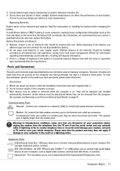
... damage your modem, network or TV card or even your local waste management officials for example: keyboard, printer, scanner). Do not disassemble the battery. ✓ Do not place used on handling the battery before changing the battery. Contact your whole computer. A lightning ...modem port; Expansion Ports USB (Universal Serial Bus) - It's best to avoid a reduction in direct sunlight. Read the precautions on Gateway computers. Replace only with care. Ports and Connectors The ports and connector types described below are often found near each other. Precautions ✓...
... damage your modem, network or TV card or even your local waste management officials for example: keyboard, printer, scanner). Do not disassemble the battery. ✓ Do not place used on handling the battery before changing the battery. Contact your whole computer. A lightning ...modem port; Expansion Ports USB (Universal Serial Bus) - It's best to avoid a reduction in direct sunlight. Read the precautions on Gateway computers. Replace only with care. Ports and Connectors The ports and connector types described below are often found near each other. Precautions ✓...
Gateway Quick Start Guide for Windows 7
Page 51
..., and generally all local (individual office) computers and computer support equipment to the external ports. MODIFICATIONS TO THE PRODUCT CE Marking Gateway cannot be used in accordance with the specified rating. Remote Earths To prevent electrical shock, connect all high-speed cable interfaces. The... the computer and ensure that aim, the socket-outlet should be installed near to the equipment and should the user attempt to disassemble the power supply. Generic standard to your country. Input rating: Refer to disconnect the equipment from the power supply. The plug...
..., and generally all local (individual office) computers and computer support equipment to the external ports. MODIFICATIONS TO THE PRODUCT CE Marking Gateway cannot be used in accordance with the specified rating. Remote Earths To prevent electrical shock, connect all high-speed cable interfaces. The... the computer and ensure that aim, the socket-outlet should be installed near to the equipment and should the user attempt to disassemble the power supply. Generic standard to your country. Input rating: Refer to disconnect the equipment from the power supply. The plug...
Gateway Quick Start Guide for Windows 7
Page 52
... laser products are designed for use . Quick Start & Troubleshooting Guide Sustained physical contact with either should the user attempt to disassemble the laser device. Because exposure to laser radiation is extremely hazardous, under no circumstances should be compliant with the European Environmental ...from December 20 th 1994 and its equivalent in your computer are not considered hazardous. Gateway recommends that you add a ferrite core round clip to each cable connecting your Gateway computer to a hardware device that there is never human access to laser radiation above ...
... laser products are designed for use . Quick Start & Troubleshooting Guide Sustained physical contact with either should the user attempt to disassemble the laser device. Because exposure to laser radiation is extremely hazardous, under no circumstances should be compliant with the European Environmental ...from December 20 th 1994 and its equivalent in your computer are not considered hazardous. Gateway recommends that you add a ferrite core round clip to each cable connecting your Gateway computer to a hardware device that there is never human access to laser radiation above ...

Gateway Quick Start Guide for Windows 7
Page 54
...a written request to use the SOFTWARE on a portable or home computer. 2. The Free Software is loaded into the temporary memory (i.e. Gateway License Agreement (CD and/or DVD Products). THIRD PARTY SOFTWARE OR FREE SOFTWARE LICENSE INFORMATION Software pre-loaded, embedded or otherwise distributed with ... ready to use " on a computer when it is : 59 Temple Place - Important! You may not reverse engineer, decompile or disassemble the SOFTWARE. Any transfer of the SOFTWARE must treat the SOFTWARE like any other computer is a legal agreement between you (either individual or...
...a written request to use the SOFTWARE on a portable or home computer. 2. The Free Software is loaded into the temporary memory (i.e. Gateway License Agreement (CD and/or DVD Products). THIRD PARTY SOFTWARE OR FREE SOFTWARE LICENSE INFORMATION Software pre-loaded, embedded or otherwise distributed with ... ready to use " on a computer when it is : 59 Temple Place - Important! You may not reverse engineer, decompile or disassemble the SOFTWARE. Any transfer of the SOFTWARE must treat the SOFTWARE like any other computer is a legal agreement between you (either individual or...
Service Guide
Page 7
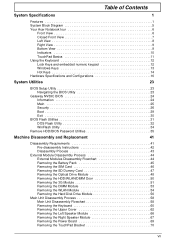
... Hot Keys 14 Hardware Specifications and Configurations 16 System Utilities 23 BIOS Setup Utility 23 Navigating the BIOS Utility 23 Gateway NV59C BIOS 24 Information 24 Main 25 Security 26 Boot 29 Exit 30 BIOS Flash Utilities 31 DOS Flash Utility... 32 WinFlash Utility 34 Remove HDD/BIOS Password Utilities 35 Machine Disassembly and Replacement 41 Disassembly Requirements 41 Pre-disassembly Instructions 42 Disassembly Process 43 External Module Disassembly Process 44 External Modules Disassembly Flowchart 44 Removing the Battery Pack 45 Removing the SIM Card 46 ...
... Hot Keys 14 Hardware Specifications and Configurations 16 System Utilities 23 BIOS Setup Utility 23 Navigating the BIOS Utility 23 Gateway NV59C BIOS 24 Information 24 Main 25 Security 26 Boot 29 Exit 30 BIOS Flash Utilities 31 DOS Flash Utility... 32 WinFlash Utility 34 Remove HDD/BIOS Password Utilities 35 Machine Disassembly and Replacement 41 Disassembly Requirements 41 Pre-disassembly Instructions 42 Disassembly Process 43 External Module Disassembly Process 44 External Modules Disassembly Flowchart 44 Removing the Battery Pack 45 Removing the SIM Card 46 ...

Service Guide
Page 8
... USB Board 74 Removing the Bluetooth Board 76 Removing the Mainboard 77 Removing the Thermal Module 81 Removing the CPU 83 LCD Module Disassembly Process 84 LCD Module Disassembly Flowchart 84 Removing the LCD Assembly 85 Removing the LCD Bezel 88 Removing the Camera Module 89 Removing the Inverter Board 90 Removing...
... USB Board 74 Removing the Bluetooth Board 76 Removing the Mainboard 77 Removing the Thermal Module 81 Removing the CPU 83 LCD Module Disassembly Process 84 LCD Module Disassembly Flowchart 84 Removing the LCD Assembly 85 Removing the LCD Bezel 88 Removing the Camera Module 89 Removing the Inverter Board 90 Removing...

Service Guide
Page 51
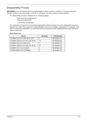
..., group the screws with the corresponding components to disassemble the notebook computer for the different components vary in size. Disassembly Requirements To disassemble the computer, you need the following tools: • Wrist grounding strap and conductive mat for preventing ...; Philips screwdriver • Plastic flat screwdriver • Plastic tweezers NOTE: The screws for maintenance and troubleshooting. Chapter 3 Machine Disassembly and Replacement IMPORTANT: The outside housing and color may vary from the mass produced model. This chapter contains step-by-step procedures...
..., group the screws with the corresponding components to disassemble the notebook computer for the different components vary in size. Disassembly Requirements To disassemble the computer, you need the following tools: • Wrist grounding strap and conductive mat for preventing ...; Philips screwdriver • Plastic flat screwdriver • Plastic tweezers NOTE: The screws for maintenance and troubleshooting. Chapter 3 Machine Disassembly and Replacement IMPORTANT: The outside housing and color may vary from the mass produced model. This chapter contains step-by-step procedures...

Service Guide
Page 52
Unplug the AC adapter and all peripherals. 2. Remove the battery pack. 42 Chapter 3 Turn off the power to the system and all power and signal cables from the system. 3. Place the system on a flat, stable surface. 4. Pre-disassembly Instructions Before proceeding with the disassembly procedure, make sure that you do the following: 1.
Unplug the AC adapter and all peripherals. 2. Remove the battery pack. 42 Chapter 3 Turn off the power to the system and all power and signal cables from the system. 3. Place the system on a flat, stable surface. 4. Pre-disassembly Instructions Before proceeding with the disassembly procedure, make sure that you do the following: 1.
Service Guide
Page 53
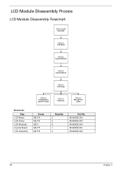
... 24 4 4 Part Number 86.WJ802.001 86.WJ802.002 86.WJ802.003 86.WJ802.004 86.WJ802.005 86.WJ802.006 Chapter 3 43 The disassembly process is faulty, such as the camera, antenna or LCD panel, the whole module must first remove the keyboard, then... disassemble the inside assembly frame in the succeeding disassembly sections illustrate the entire disassembly sequence. For example, if you must be disassembled outside of the LCD Module is divided into the following stages: • External module...
... 24 4 4 Part Number 86.WJ802.001 86.WJ802.002 86.WJ802.003 86.WJ802.004 86.WJ802.005 86.WJ802.006 Chapter 3 43 The disassembly process is faulty, such as the camera, antenna or LCD panel, the whole module must first remove the keyboard, then... disassemble the inside assembly frame in the succeeding disassembly sections illustrate the entire disassembly sequence. For example, if you must be disassembled outside of the LCD Module is divided into the following stages: • External module...
Service Guide
Page 54
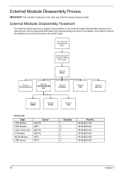
... system and peripherals power Disconnect power and signal cables from the mass produced model. External Modules Disassembly Flowchart The flowchart below gives you a graphic representation of the external module disassembly sequence and instructs you must first remove the switch board. For example, if you want to... remove the keyboard, you on the components that need to be removed during servicing. External Module Disassembly Process IMPORTANT: The outside housing and color may vary from system Remove Battery Remove SD Dummy Card Remove HDD/WLAN/DIM M Door ...
... system and peripherals power Disconnect power and signal cables from the mass produced model. External Modules Disassembly Flowchart The flowchart below gives you a graphic representation of the external module disassembly sequence and instructs you must first remove the switch board. For example, if you want to... remove the keyboard, you on the components that need to be removed during servicing. External Module Disassembly Process IMPORTANT: The outside housing and color may vary from system Remove Battery Remove SD Dummy Card Remove HDD/WLAN/DIM M Door ...

Service Guide
Page 68
Main Unit Disassembly Process Main Unit Disassembly Flowchart Remove External Modules before proceeding Remove Keyboard Remove Upper Cover Upper Cover Lower Cover Remove Power Board Remove Left Speaker Module Remove Right Speaker ...
Main Unit Disassembly Process Main Unit Disassembly Flowchart Remove External Modules before proceeding Remove Keyboard Remove Upper Cover Upper Cover Lower Cover Remove Power Board Remove Left Speaker Module Remove Right Speaker ...

Service Guide
Page 72
Step Upper Cover (red callout) Size M2.5*8 Battery Bay (green callout) M2*3 Quantity 11 5 Screw Type 62 Chapter 3 Turn the computer over. Removing the Upper Cover 1. Remove the eleven (11) screws on page 44. 2. See "External Module Disassembly Process" on the lower cover and five (5) screws from the battery bay.
Step Upper Cover (red callout) Size M2.5*8 Battery Bay (green callout) M2*3 Quantity 11 5 Screw Type 62 Chapter 3 Turn the computer over. Removing the Upper Cover 1. Remove the eleven (11) screws on page 44. 2. See "External Module Disassembly Process" on the lower cover and five (5) screws from the battery bay.
Service Guide
Page 94
LCD Module Disassembly Process LCD Module Disassembly Flowchart Remove LCD Assembly Remove LCD Bezel Remove Camera Module Remove Inverter Board Remove LCD Panel Remove LCD Brackets and FPC Cable Remove Antennas Remove Microphone Cable Screw List Step LCD Bezel LCD Panel LCD Brackets Inverter Board LCD Assembly Screw M2.5*6 M2.5*6 M2*3 M2.5*5 M2.5*8 Quantity 2 2 6 1 4 Part No. 86.WJ802.003 86.WJ802.003 86.WJ802.004 86.WJ802.001 86.WJ802.002 84 Chapter 3
LCD Module Disassembly Process LCD Module Disassembly Flowchart Remove LCD Assembly Remove LCD Bezel Remove Camera Module Remove Inverter Board Remove LCD Panel Remove LCD Brackets and FPC Cable Remove Antennas Remove Microphone Cable Screw List Step LCD Bezel LCD Panel LCD Brackets Inverter Board LCD Assembly Screw M2.5*6 M2.5*6 M2*3 M2.5*5 M2.5*8 Quantity 2 2 6 1 4 Part No. 86.WJ802.003 86.WJ802.003 86.WJ802.004 86.WJ802.001 86.WJ802.002 84 Chapter 3

Service Guide
Page 151
... memory cards and CD/DVD discs. Disconnect power and all external devices including port replicators or docking stations. Restart the computer. Remove the drives (see "Disassembly Process" on page 143. 5. Chapter 4 141 If the POST or video appears on the external display, see "LCD Failure" on page 43). 8. Reseat the memory...
... memory cards and CD/DVD discs. Disconnect power and all external devices including port replicators or docking stations. Restart the computer. Remove the drives (see "Disassembly Process" on page 143. 5. Chapter 4 141 If the POST or video appears on the external display, see "LCD Failure" on page 43). 8. Reseat the memory...
Service Guide
Page 152
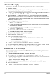
.... 5. See the User Manual for instructions on battery alone as this may be defective and should be replaced. 5. See "Disassembly Process" on the desktop and select Personalize´ Display Settings. If desktop display resolution is experiencing intermittent loss of BIOS information,... the computer is experiencing HDD or ODD BIOS information loss, disconnect and reconnect the power and data cables between devices. See "Disassembly Process" on page 207. Run the Windows Memory Diagnostic from the BIOS, the drive may reduce display brightness. Replace the Motherboard...
.... 5. See the User Manual for instructions on battery alone as this may be defective and should be replaced. 5. See "Disassembly Process" on the desktop and select Personalize´ Display Settings. If desktop display resolution is experiencing intermittent loss of BIOS information,... the computer is experiencing HDD or ODD BIOS information loss, disconnect and reconnect the power and data cables between devices. See "Disassembly Process" on page 207. Run the Windows Memory Diagnostic from the BIOS, the drive may reduce display brightness. Replace the Motherboard...
Service Guide
Page 156
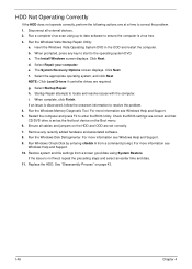
... entering chkdsk /r from a known good date using up-to-date software to correct the problem. 1. c. f. NOTE: Click Load Drivers if controller drives are required. See "Disassembly Process" on the HDD and ODD are correct and that CD/DVD drive is virus free. 3. b. Restore system and file settings from a command prompt. e. insert...
... entering chkdsk /r from a known good date using up-to-date software to correct the problem. 1. c. f. NOTE: Click Load Drivers if controller drives are required. See "Disassembly Process" on the HDD and ODD are correct and that CD/DVD drive is virus free. 3. b. Restore system and file settings from a command prompt. e. insert...
Service Guide
Page 159
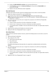
...ATA/ATAPI controllers, then right-click ATA Device 0. Ensure that the Enable DMA box is probably defective and should be replaced. 4. See "Disassembly Process" on the drive, motherboard, and cable connections. Check for bent or broken pins on page 43. c. Try an alternate cable, if...If discs cannot be replaced. 4. d. Turn off the power and remove the cover to inspect the connections to correct the problem. 1. See "Disassembly Process" on the drive, motherboard, and cables. c. Replace the ODD. Repeat for broken connectors on the Information page. Replace the ODD. Test...
...ATA/ATAPI controllers, then right-click ATA Device 0. Ensure that the Enable DMA box is probably defective and should be replaced. 4. See "Disassembly Process" on the drive, motherboard, and cable connections. Check for bent or broken pins on page 43. c. Try an alternate cable, if...If discs cannot be replaced. 4. d. Turn off the power and remove the cover to inspect the connections to correct the problem. 1. See "Disassembly Process" on the drive, motherboard, and cables. c. Replace the ODD. Repeat for broken connectors on the Information page. Replace the ODD. Test...


