8512949 - Component Replacement Manual R0
Page 1
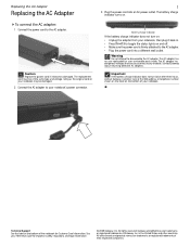
... turn on: • Unplug the adapter from your Reference Guide for Customer Care Information. All rights reserved. The replacement cord must be damaged. 2 Connect the AC adapter to toggle the status lights on the bottom of Gateway, Inc. All other countries. Replacing the AC Adapter Replacing the AC Adapter To connect the AC adapter: 1 Connect the power cord to disassemble the AC adapter. The AC adapter has no user-replaceable or user-serviceable parts...
... turn on: • Unplug the adapter from your Reference Guide for Customer Care Information. All rights reserved. The replacement cord must be damaged. 2 Connect the AC adapter to toggle the status lights on the bottom of Gateway, Inc. All other countries. Replacing the AC Adapter Replacing the AC Adapter To connect the AC adapter: 1 Connect the power cord to disassemble the AC adapter. The AC adapter has no user-replaceable or user-serviceable parts...
8512949 - Component Replacement Manual R0
Page 2
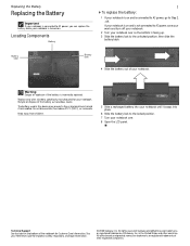
... if the battery is incorrectly replaced. Locating Components Battery 1 To replace the battery: 1 If your notebook is on and is connected to AC power, go to Step 2. -ORIf your notebook is on and is not connected to AC power, save your work and turn off your notebook. 2 Turn your notebook over so the bottom is facing up. 3 Slide the battery lock to the locked position. 7 Turn your notebook over. 8 Open the LCD panel. The battery used in...
... if the battery is incorrectly replaced. Locating Components Battery 1 To replace the battery: 1 If your notebook is on and is connected to AC power, go to Step 2. -ORIf your notebook is on and is not connected to AC power, save your work and turn off your notebook. 2 Turn your notebook over so the bottom is facing up. 3 Slide the battery lock to the locked position. 7 Turn your notebook over. 8 Open the LCD panel. The battery used in...
8512949 - Component Replacement Manual R0
Page 3
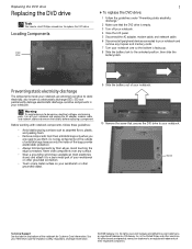
... trademarks of your notebook. 10 Remove the screw that the DVD drive is empty. 3 Turn off your notebook. 4 Close the LCD panel. 5 Disconnect the AC adapter, modem cable, and network cable. 6 Disconnect all peripheral devices connected to your notebook and remove any Express and memory cards. 7 Turn your notebook over any surface. • Wear a grounding wrist strap (available at most electronics stores) and attach it to a bare metal part of your...
... trademarks of your notebook. 10 Remove the screw that the DVD drive is empty. 3 Turn off your notebook. 4 Close the LCD panel. 5 Disconnect the AC adapter, modem cable, and network cable. 6 Disconnect all peripheral devices connected to your notebook and remove any Express and memory cards. 7 Turn your notebook over any surface. • Wear a grounding wrist strap (available at most electronics stores) and attach it to a bare metal part of your...
8512949 - Component Replacement Manual R0
Page 4
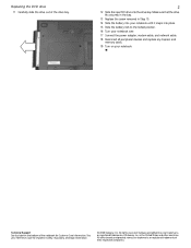
... the drive fits securely in the bay. 13 Replace the screw removed in the United States and other brands and product names are trademarks or registered trademarks of their respective companies. See your notebook over. 17 Connect the power adapter, modem cable, and network cable. 18 Reconnect all peripheral devices and replace any Express and memory cards. 19 Turn on the bottom of the notebook for...
... the drive fits securely in the bay. 13 Replace the screw removed in the United States and other brands and product names are trademarks or registered trademarks of their respective companies. See your notebook over. 17 Connect the power adapter, modem cable, and network cable. 18 Reconnect all peripheral devices and replace any Express and memory cards. 19 Turn on the bottom of the notebook for...
8512949 - Component Replacement Manual R0
Page 5
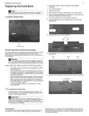
... create a Drivers and Applications Recovery disc, Gateway may send you are trademarks or registered trademarks of the notebook for software and device driver recovery" in the United States and other brands and product names are ready to replace the hard drive. Warning To avoid exposure to dangerous electrical voltages and moving parts, turn off your notebook. 4 Close the LCD panel. 5 Disconnect the AC adapter, modem cable, and network cable. 6 Disconnect all peripheral devices connected...
... create a Drivers and Applications Recovery disc, Gateway may send you are trademarks or registered trademarks of the notebook for software and device driver recovery" in the United States and other brands and product names are ready to replace the hard drive. Warning To avoid exposure to dangerous electrical voltages and moving parts, turn off your notebook. 4 Close the LCD panel. 5 Disconnect the AC adapter, modem cable, and network cable. 6 Disconnect all peripheral devices connected...
8512949 - Component Replacement Manual R0
Page 6
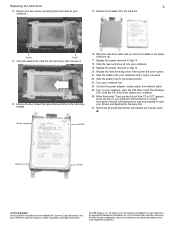
... power adapter, modem cable, and network cable 25 Turn on your notebook. 15 Remove the bracket from CD or DVD" appears, press any Express cards. Replacing the hard drive 2 12 Remove the two screws connecting the hard drive to your keyboard and follow the on-screen instructions. All rights reserved. All other countries. See your Drivers and Applications Recovery disc. 27 Reconnect all peripheral devices and replace any key on your notebook, open the DVD drive, insert the Windows DVD, close the DVD drive...
... power adapter, modem cable, and network cable 25 Turn on your notebook. 15 Remove the bracket from CD or DVD" appears, press any Express cards. Replacing the hard drive 2 12 Remove the two screws connecting the hard drive to your keyboard and follow the on-screen instructions. All rights reserved. All other countries. See your Drivers and Applications Recovery disc. 27 Reconnect all peripheral devices and replace any key on your notebook, open the DVD drive, insert the Windows DVD, close the DVD drive...
8512949 - Component Replacement Manual R0
Page 7
... up . 13 Pull the cover off your notebook. 3 Close the LCD panel. 4 Disconnect the AC adapter, modem cable, and network cable. -OR- 5 Disconnect all peripheral devices connected to your notebook and remove any Express and memory cards. 6 Turn your notebook over any surface. • Wear a grounding wrist strap (available at most electronics stores) and attach it to use them in a safe place. To replace the keyboard: 1 Follow the guidelines under...
... up . 13 Pull the cover off your notebook. 3 Close the LCD panel. 4 Disconnect the AC adapter, modem cable, and network cable. -OR- 5 Disconnect all peripheral devices connected to your notebook and remove any Express and memory cards. 6 Turn your notebook over any surface. • Wear a grounding wrist strap (available at most electronics stores) and attach it to use them in a safe place. To replace the keyboard: 1 Follow the guidelines under...
8512949 - Component Replacement Manual R0
Page 8
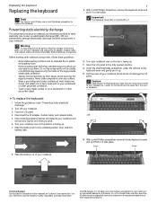
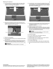
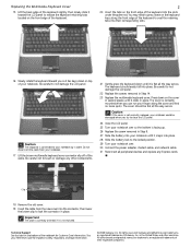
... to close the LCD panel. 24 Close the LCD panel. 25 Turn your notebook over . 30 Connect the power adapter, modem cable, and network cable 31 Reconnect all peripheral devices and replace any other components. The cover should easily fall into place. in the United States and other brands and product names are fully moved toward the LCD panel to release the keyboard retaining tabs located on the front...
... to close the LCD panel. 24 Close the LCD panel. 25 Turn your notebook over . 30 Connect the power adapter, modem cable, and network cable 31 Reconnect all peripheral devices and replace any other components. The cover should easily fall into place. in the United States and other brands and product names are fully moved toward the LCD panel to release the keyboard retaining tabs located on the front...
8512949 - Component Replacement Manual R0
Page 9
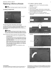
... avoid exposure to replace a memory module. Screw 10 Lift the memory bay cover, then remove it to the unlocked position, then slide the battery latch. All rights reserved. in your notebook. Replacing a Memory Module Replacing a Memory Module Tools You need a small Phillips screwdriver to dangerous electrical voltages and moving parts, turn off your notebook. 3 Close the LCD panel. 4 Disconnect the AC adapter, modem cable, and network cable. 5 Disconnect all peripheral devices connected to your notebook and remove any surface...
... avoid exposure to replace a memory module. Screw 10 Lift the memory bay cover, then remove it to the unlocked position, then slide the battery latch. All rights reserved. in your notebook. Replacing a Memory Module Replacing a Memory Module Tools You need a small Phillips screwdriver to dangerous electrical voltages and moving parts, turn off your notebook. 3 Close the LCD panel. 4 Disconnect the AC adapter, modem cable, and network cable. 5 Disconnect all peripheral devices connected to your notebook and remove any surface...
8512949 - Component Replacement Manual R0
Page 10
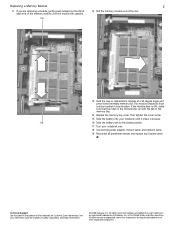
... notebook over. 18 Connect the power adapter, modem cable, and network cable 19 Reconnect all peripheral devices and replace any Express cards. Clip 13 Hold the new or replacement module at each end of the memory module until it snaps into the empty memory slot. If the module does not fit, make sure that the notch in the module lines up with the tab in the memory bay. 14 Replace the memory bay cover...
... notebook over. 18 Connect the power adapter, modem cable, and network cable 19 Reconnect all peripheral devices and replace any Express cards. Clip 13 Hold the new or replacement module at each end of the memory module until it snaps into the empty memory slot. If the module does not fit, make sure that the notch in the module lines up with the tab in the memory bay. 14 Replace the memory bay cover...
8512949 - Component Replacement Manual R0
Page 11
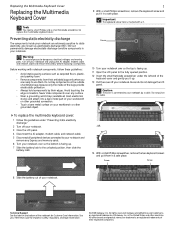
... the battery lock to dangerous electrical voltages and moving parts, turn off your notebook. Gateway and eMachines are trademarks or registered trademarks of the keyboard cover and gently pry it in your Reference Guide for Customer Care Information. Avoid touching the edge connectors. Important The keyboard screw hole is facing up. 11 Open the LCD panel to your notebook. Screw 10 Turn your notebook are ready to use...
... the battery lock to dangerous electrical voltages and moving parts, turn off your notebook. Gateway and eMachines are trademarks or registered trademarks of the keyboard cover and gently pry it in your Reference Guide for Customer Care Information. Avoid touching the edge connectors. Important The keyboard screw hole is facing up. 11 Open the LCD panel to your notebook. Screw 10 Turn your notebook are ready to use...
8512949 - Component Replacement Manual R0
Page 12
Do not disconnect the cable from the new cover into place. Be careful not to the locked position. 29 Turn your notebook over. 30 Connect the power adapter, modem cable, and network cable 31 Reconnect all peripheral devices and replace any other components. 21 Gently press the keyboard down on the cover in several places until it is correctly oriented if it lies keys-down on the front...
Do not disconnect the cable from the new cover into place. Be careful not to the locked position. 29 Turn your notebook over. 30 Connect the power adapter, modem cable, and network cable 31 Reconnect all peripheral devices and replace any other components. 21 Gently press the keyboard down on the cover in several places until it is correctly oriented if it lies keys-down on the front...
8512949 - Component Replacement Manual R0
Page 13
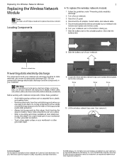
... exposure to dangerous electrical voltages and moving parts, turn off your notebook. 3 Close the LCD panel. 4 Disconnect the AC adapter, modem cable, and network cable. 5 Disconnect all peripheral devices connected to static electricity, also known as carpeted floors, plastic, and packing foam. • Remove components from their edges. All other grounded object. 9 Loosen the three wireless network bay cover screws (these guidelines: • Avoid static...
... exposure to dangerous electrical voltages and moving parts, turn off your notebook. 3 Close the LCD panel. 4 Disconnect the AC adapter, modem cable, and network cable. 5 Disconnect all peripheral devices connected to static electricity, also known as carpeted floors, plastic, and packing foam. • Remove components from their edges. All other grounded object. 9 Loosen the three wireless network bay cover screws (these guidelines: • Avoid static...
8512949 - Component Replacement Manual R0
Page 14
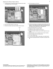
... color cable is keyed so it into place. 21 Slide the battery lock to the locked position. 22 Turn your notebook over. 23 Connect the power adapter, modem cable, and network cable 24 Reconnect all peripheral devices and replace any Express cards. Screw 15 Hold the new module at a 30-degree angle and insert it can only be inserted in one direction. If the module does not fit, make sure...
... color cable is keyed so it into place. 21 Slide the battery lock to the locked position. 22 Turn your notebook over. 23 Connect the power adapter, modem cable, and network cable 24 Reconnect all peripheral devices and replace any Express cards. Screw 15 Hold the new module at a 30-degree angle and insert it can only be inserted in one direction. If the module does not fit, make sure...


