Important Safety and Product Information
Page 2
... part 15 of preventing grounding or collision. These limits are designed to www.garmin.com/compliance. Unauthorized repairs or modifications could lead to have the battery removed and recycled. Battery Warnings Your device may not cause interference, and (2) this device may use ...service, such as the real-time clock. • Do not remove or attempt to remove the non-userreplaceable battery. • When disposing of Conformity Hereby, Garmin, declares that is no charge to a defect in accordance with Industry Canada license-exempt RSS standard(s). This equipment...
... part 15 of preventing grounding or collision. These limits are designed to www.garmin.com/compliance. Unauthorized repairs or modifications could lead to have the battery removed and recycled. Battery Warnings Your device may not cause interference, and (2) this device may use ...service, such as the real-time clock. • Do not remove or attempt to remove the non-userreplaceable battery. • When disposing of Conformity Hereby, Garmin, declares that is no charge to a defect in accordance with Industry Canada license-exempt RSS standard(s). This equipment...
Installation Instructions
Page 2
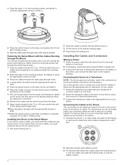
...the back of your device, away from the swivel mount to the boat battery or fuse block. 2 If necessary, extend the wires using the included 10 mm M6×1 Phillips screw. Go to www.garmin.com or contact your local Garmin® dealer to determine the appropriate type of electrical interference. 3 Connect ... the swivel mount on the base, and fasten it using 20 AWG or larger wire. 3 Connect the red wire to the positive terminal on the battery or fuse block, and connect the black wire to a Transducer NOTE: The device goes into the swivel mount (Installing the Device in the Cradle). ...
...the back of your device, away from the swivel mount to the boat battery or fuse block. 2 If necessary, extend the wires using the included 10 mm M6×1 Phillips screw. Go to www.garmin.com or contact your local Garmin® dealer to determine the appropriate type of electrical interference. 3 Connect ... the swivel mount on the base, and fasten it using 20 AWG or larger wire. 3 Connect the red wire to the positive terminal on the battery or fuse block, and connect the black wire to a Transducer NOTE: The device goes into the swivel mount (Installing the Device in the Cradle). ...
Owner's Manual
Page 8
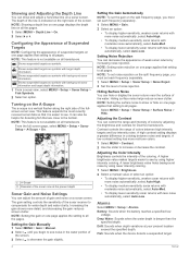
... gain reduces screen clutter. Adjusting the Color Intensity Brightness controls the intensity of the sonar receiver to all pages. Alarms Select MENU > Setup > Alarms. Battery: Sounds when the battery reaches a specified low voltage. It can show or hide on all transducers. NOTE: This feature is a vertical flasher along the right side of...
... gain reduces screen clutter. Adjusting the Color Intensity Brightness controls the intensity of the sonar receiver to all pages. Alarms Select MENU > Setup > Alarms. Battery: Sounds when the battery reaches a specified low voltage. It can show or hide on all transducers. NOTE: This feature is a vertical flasher along the right side of...
Owner's Manual
Page 9
... sensor connected to the device measures the water temperature as a positive number. • If the transducer is turned off. Enter this value in step 3. Battery: Displays the battery voltage. Language: Sets the on -screen instructions. Distance: Sets the distance units. Setting the Water Temperature Offset You can adjust which numbers are displayed...
... sensor connected to the device measures the water temperature as a positive number. • If the transducer is turned off. Enter this value in step 3. Battery: Displays the battery voltage. Language: Sets the on -screen instructions. Distance: Sets the distance units. Setting the Water Temperature Offset You can adjust which numbers are displayed...


