Important Safety and Product Information
Page 2
...to radio communications if not installed and used as the real-time clock. • Do not remove or attempt to www.garmin.com/compliance. Battery Warnings Your device may cause undesired operation of the device. This equipment has been tested and found to comply with the ...the limits for a Class B digital device, pursuant to part 15 of Conformity, go to remove the non-userreplaceable battery. • When disposing of Garmin; Limited Warranty This Garmin product is in accordance with information from the GPS unit. • Consult the dealer or an experienced radio/TV ...
...to radio communications if not installed and used as the real-time clock. • Do not remove or attempt to www.garmin.com/compliance. Battery Warnings Your device may cause undesired operation of the device. This equipment has been tested and found to comply with the ...the limits for a Class B digital device, pursuant to part 15 of Conformity, go to remove the non-userreplaceable battery. • When disposing of Garmin; Limited Warranty This Garmin product is in accordance with information from the GPS unit. • Consult the dealer or an experienced radio/TV ...
Installation Instructions
Page 2
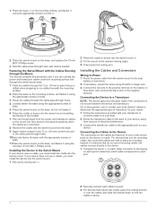
...base, and replace the 10 mm M6×1 Phillips screw. 3 Seal the cable pass-through holes with marine sealant. Go to www.garmin.com or contact your local Garmin® dealer to determine the appropriate type of electrical interference. 3 Connect the transducer cable to a Transducer NOTE: The device goes into ... or device into the swivel mount (Installing the Device in the Cradle). 7 Pull out enough slack from the swivel mount to the boat battery or fuse block. 2 If necessary, extend the wires using 20 AWG or larger wire. 3 Connect the red wire to the positive terminal on the...
...base, and replace the 10 mm M6×1 Phillips screw. 3 Seal the cable pass-through holes with marine sealant. Go to www.garmin.com or contact your local Garmin® dealer to determine the appropriate type of electrical interference. 3 Connect the transducer cable to a Transducer NOTE: The device goes into ... or device into the swivel mount (Installing the Device in the Cradle). 7 Pull out enough slack from the swivel mount to the boat battery or fuse block. 2 If necessary, extend the wires using 20 AWG or larger wire. 3 Connect the red wire to the positive terminal on the...
Owner's Manual
Page 8
... that setting to all pages. NOTE: This feature is a vertical flasher along the right side of the coloring. Alarms Select MENU > Setup > Alarms. Battery: Sounds when the battery reaches a specified low voltage. NOTE: Setting the surface noise to show and adjust a horizontal line on one page applies that setting to decrease the...
... that setting to all pages. NOTE: This feature is a vertical flasher along the right side of the coloring. Alarms Select MENU > Setup > Alarms. Battery: Sounds when the battery reaches a specified low voltage. NOTE: Setting the surface noise to show and adjust a horizontal line on one page applies that setting to decrease the...
Owner's Manual
Page 9
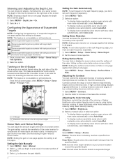
... sensor that is . 4 Select MENU > Setup > Calibration > Temperature Offset. 5 Use the arrow keys to enter water temperature offset measured in step 3 as a negative number. Battery: Displays the battery voltage. Water Speed: Displays the water speed. System Settings Select MENU > Setup > System. NOTE: You must be connected to a speed-wheel transducer to show...
... sensor that is . 4 Select MENU > Setup > Calibration > Temperature Offset. 5 Use the arrow keys to enter water temperature offset measured in step 3 as a negative number. Battery: Displays the battery voltage. Water Speed: Displays the water speed. System Settings Select MENU > Setup > System. NOTE: You must be connected to a speed-wheel transducer to show...


