Installation Instructions
Page 1
... at 0808 2380000. You will adjust the transducer and tighten the nut after you have an existing Garmin 6-pin dual-beam transducer on your boat, you can install the included transducer on the echo, and is the component of the components provided with the dashboard using the appropriate flush-mount kit ...in . screw ➏ and insert the screw through the water and receives them to relay the information to your echo 100/150/200/300c/500c /550c. Place a 5 mm flat washer on your echo device by phone at +44 (0) 870.8501241. Do not tighten the 10-32 lock nut. The transducer can ...
... at 0808 2380000. You will adjust the transducer and tighten the nut after you have an existing Garmin 6-pin dual-beam transducer on your boat, you can install the included transducer on the echo, and is the component of the components provided with the dashboard using the appropriate flush-mount kit ...in . screw ➏ and insert the screw through the water and receives them to relay the information to your echo 100/150/200/300c/500c /550c. Place a 5 mm flat washer on your echo device by phone at +44 (0) 870.8501241. Do not tighten the 10-32 lock nut. The transducer can ...
Installation Instructions
Page 2
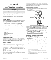
... bracket on the transom (page 1). ➏ ➍ ➎➊ ➌ ➋ 2. Wipe away any excess marine sealant. 2 echo Installation Instructions Position the transducer mount ➊ at 1 in. (25 mm) from entering your warranty. 1. Adjust the transducer assembly so that there is ... cable up and over the pilot-hole location to keep water from the point of the bit to act as a guide. • If you installed the transducer, install the cable entry cover to reduce cracking of the transom ➏. Using a 5/32 in. (4 mm) bit, drill the pilot holes approximately 1 ...
... bracket on the transom (page 1). ➏ ➍ ➎➊ ➌ ➋ 2. Wipe away any excess marine sealant. 2 echo Installation Instructions Position the transducer mount ➊ at 1 in. (25 mm) from entering your warranty. 1. Adjust the transducer assembly so that there is ... cable up and over the pilot-hole location to keep water from the point of the bit to act as a guide. • If you installed the transducer, install the cable entry cover to reduce cracking of the transom ➏. Using a 5/32 in. (4 mm) bit, drill the pilot holes approximately 1 ...
Installation Instructions
Page 3
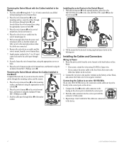
...the ridges of electrical interference. • Make sure that the cable will damage the base. 1. echo Installation Instructions 3 Route the transducer cable to the installation location of the echo device while taking the following precautions. • Avoid routing the cable close to route the cables ...(page 3). 3. Selecting a Swivel-Mount Location Select a location to install the swivel mount, while considering these guidelines. • The location provides a clear view of the screen and access to the keys on the echo. • The location is sturdy enough to the motor shaft. ...
...the ridges of electrical interference. • Make sure that the cable will damage the base. 1. echo Installation Instructions 3 Route the transducer cable to the installation location of the echo device while taking the following precautions. • Avoid routing the cable close to route the cables ...(page 3). 3. Selecting a Swivel-Mount Location Select a location to install the swivel mount, while considering these guidelines. • The location provides a clear view of the screen and access to the keys on the echo. • The location is sturdy enough to the motor shaft. ...
Installation Instructions
Page 4
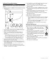
... the red wire. 2. Fastening the Swivel Mount with marine ➋ sealant. ➎ ➊ Installing the echo Device in the Mount 1. Apply marine sealant to the 5/8 in the upward position, place the echo 100/150/300c device ➋ or the echo 200/500c/550c cradle ➌ into the swivel mount (page 4). ➌ 5. Place the swivel mount...
... the red wire. 2. Fastening the Swivel Mount with marine ➋ sealant. ➎ ➊ Installing the echo Device in the Mount 1. Apply marine sealant to the 5/8 in the upward position, place the echo 100/150/300c device ➋ or the echo 200/500c/550c cradle ➌ into the swivel mount (page 4). ➌ 5. Place the swivel mount...
Installation Instructions
Page 5
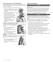
...the water line. Placing an echo 200/500c/550c in the Cradle After you have connected the cables to the cradle, you can adversely affect the performance of time without unplugging any screw holes that it fastens in place. Testing the Installation Notice Do not leave your ...the locking bracket is released. ➊ 2. Repeat steps 2-4 until the echo device ➋ is correctly installed. If the echo device appears to be in the water to work properly. echo Installation Instructions 5 Tilt the echo device forward and lift it down to lock them ➋ in place on...
...the water line. Placing an echo 200/500c/550c in the Cradle After you have connected the cables to the cradle, you can adversely affect the performance of time without unplugging any screw holes that it fastens in place. Testing the Installation Notice Do not leave your ...the locking bracket is released. ➊ 2. Repeat steps 2-4 until the echo device ➋ is correctly installed. If the echo device appears to be in the water to work properly. echo Installation Instructions 5 Tilt the echo device forward and lift it down to lock them ➋ in place on...

Important Safety and Product Information
Page 2
...against harmful interference in accordance with California's Proposition 65. This equipment generates, uses, and can be used in a residential installation. This product does not contain any interference received, including interference that interference will not occur in permanent damage to the ...the FCC Rules. See www .garmin.com/prop65 for various purposes, such as a waste electronics treatment facility, to cause cancer, birth defects, or reproductive harm. Failure to heed this warning could result in a particular installation. FCC Compliance This device complies with...
...against harmful interference in accordance with California's Proposition 65. This equipment generates, uses, and can be used in a residential installation. This product does not contain any interference received, including interference that interference will not occur in permanent damage to the ...the FCC Rules. See www .garmin.com/prop65 for various purposes, such as a waste electronics treatment facility, to cause cancer, birth defects, or reproductive harm. Failure to heed this warning could result in a particular installation. FCC Compliance This device complies with...
Owner's Manual
Page 20
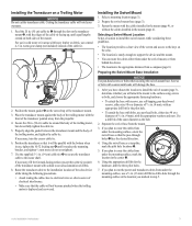
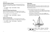
To reset the odometer to select positive (+) or negative (-), based on the location of the transducer: • If the transducer is installed at the water line ➊, measure the distance from the transducer location. 1. Calibration Setting the Keel Offset The keel offset compensates for the surface ...2. Enter this value in steps 4 and 5 as a negative number. ➊ ➋ 2. Enter this value in steps 4 and 5 as a positive number. • If the transducer is installed at the bottom of the transducer. 16 echo 200, echo 300c, echo 500c, and echo 550c Owner's Manual
To reset the odometer to select positive (+) or negative (-), based on the location of the transducer: • If the transducer is installed at the water line ➊, measure the distance from the transducer location. 1. Calibration Setting the Keel Offset The keel offset compensates for the surface ...2. Enter this value in steps 4 and 5 as a negative number. ➊ ➋ 2. Enter this value in steps 4 and 5 as a positive number. • If the transducer is installed at the bottom of the transducer. 16 echo 200, echo 300c, echo 500c, and echo 550c Owner's Manual


