Installation Instructions
Page 1
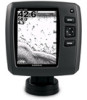
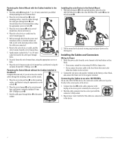
...strakes, struts, fittings, water intake or discharge ports, or anything that creates air bubbles or causes the water to www.garmin.com/support, or contact Garmin USA by installing an adapter cable (sold separately). ➍ ➏➎ ➊➋ ➐ ➌ 2. screw ➏...10123; into the mounting bracket ➍. 3. The transducer must be mounted flush with your echo 100/150/200/300c/500c /550c. When planning a mounting location, choose a location that you can install the included transducer on the transom of your boat (page 1) or on your trolling motor...
...strakes, struts, fittings, water intake or discharge ports, or anything that creates air bubbles or causes the water to www.garmin.com/support, or contact Garmin USA by installing an adapter cable (sold separately). ➍ ➏➎ ➊➋ ➐ ➌ 2. screw ➏...10123; into the mounting bracket ➍. 3. The transducer must be mounted flush with your echo 100/150/200/300c/500c /550c. When planning a mounting location, choose a location that you can install the included transducer on the transom of your boat (page 1) or on your trolling motor...
Installation Instructions
Page 2
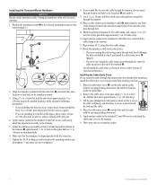
...the included 12 mm M4 screws, and attach the cable-entry cover to the transom. 5. Wipe away any excess marine sealant. 2 echo Installation Instructions Align the transducer parallel with the water line. 7. Place a cable clamp on the transducer mount. 3. Fill the pass-through the... transom (page 1). ➏ ➍ ➎➊ ➌ ➋ 2. Avoid routing the cable close to the transom. 13. Installing the Transom-Mount Hardware Notice Do not cut the transducer cable. Place the cable-entry cover ➊ over the top of electrical interference. Repeat...
...the included 12 mm M4 screws, and attach the cable-entry cover to the transom. 5. Wipe away any excess marine sealant. 2 echo Installation Instructions Align the transducer parallel with the water line. 7. Place a cable clamp on the transducer mount. 3. Fill the pass-through the... transom (page 1). ➏ ➍ ➎➊ ➌ ➋ 2. Avoid routing the cable close to the transom. 13. Installing the Transom-Mount Hardware Notice Do not cut the transducer cable. Place the cable-entry cover ➊ over the top of electrical interference. Repeat...
Installation Instructions
Page 3
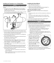
... when securing the swivel-mount base. Use a drill bit of the same diameter as a template, mark the pilot hole locations ➋. 5. echo Installation Instructions 3 For use self-tapping, pan-head wood screws, either size #8 or a diameter of electrical interference. • Make sure that the... attach the mount to drill a hole through holes ➊ face the desired direction. 4. Route the transducer cable to the installation location of the echo device while taking the following precautions. • Avoid routing the cable close to electrical wires or other sources of 5/32 in...
... when securing the swivel-mount base. Use a drill bit of the same diameter as a template, mark the pilot hole locations ➋. 5. echo Installation Instructions 3 For use self-tapping, pan-head wood screws, either size #8 or a diameter of electrical interference. • Make sure that the... attach the mount to drill a hole through holes ➊ face the desired direction. 4. Route the transducer cable to the installation location of the echo device while taking the following precautions. • Avoid routing the cable close to electrical wires or other sources of 5/32 in...
Installation Instructions
Page 4
... the wires using the included 10 mm M6×1 Phillips screw ➍. Fastening the Swivel Mount without the Cables Installed in the upward position, place the echo 100/150/300c device ➋ or the echo 200/500c/550c cradle ➌ into the swivel mount ➍. ➋ ➌ ➊ ➊ ➍ ➍ 2. With the locking...
... the wires using the included 10 mm M6×1 Phillips screw ➍. Fastening the Swivel Mount without the Cables Installed in the upward position, place the echo 100/150/300c device ➋ or the echo 200/500c/550c cradle ➌ into the swivel mount ➍. ➋ ➌ ➊ ➊ ➍ ➍ 2. With the locking...
Installation Instructions
Page 5
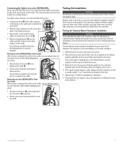
...the water. Test the transom mount transducer installation in small increments. If the signal does not improve, move the transducer to a different location on the cradle ports to identify the ➊ correct port. 2. No cables connect directly to an echo 200/500c/550c device. 1 Compare the ... in the water, check for leaks. If the sonar signal is suddenly lost or the bottom return is released. ➊ 2. echo Installation Instructions 5 Placing an echo 200/500c/550c in . (3 mm) below the water line. When you test the transducer. 1. Pay attention to your surroundings as ...
...the water. Test the transom mount transducer installation in small increments. If the signal does not improve, move the transducer to a different location on the cradle ports to identify the ➊ correct port. 2. No cables connect directly to an echo 200/500c/550c device. 1 Compare the ... in the water, check for leaks. If the sonar signal is suddenly lost or the bottom return is released. ➊ 2. echo Installation Instructions 5 Placing an echo 200/500c/550c in . (3 mm) below the water line. When you test the transducer. 1. Pay attention to your surroundings as ...

Important Safety and Product Information
Page 2
...www .garmin.com/prop65 for various purposes, such as the real-time clock. • Do not remove or attempt to remove the non-user- Failure to heed this product should only be determined by turning the equipment off and on, the user is provided in a residential installation. To...de catégorie II respecte la norme CNR310 d'Industrie Canada. 2 Operation Warning Depth data from this warning could result in a particular installation. Always operate the boat at slow speeds if you suspect shallow water or submerged objects. These limits are designed to provide reasonable protection ...
...www .garmin.com/prop65 for various purposes, such as the real-time clock. • Do not remove or attempt to remove the non-user- Failure to heed this product should only be determined by turning the equipment off and on, the user is provided in a residential installation. To...de catégorie II respecte la norme CNR310 d'Industrie Canada. 2 Operation Warning Depth data from this warning could result in a particular installation. Always operate the boat at slow speeds if you suspect shallow water or submerged objects. These limits are designed to provide reasonable protection ...
Owner's Manual
Page 20
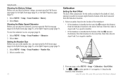
... page (page 5). 1. Select a number size. Select an option, based on the location of the transducer: • If the transducer is installed at the water line ➊, measure the distance from the transducer location. 1. Setting the Number Size Before you can show the battery voltage, you...keel instead of from the transducer location to select positive (+) or negative (-), based on the location of the transducer. 16 echo 200, echo 300c, echo 500c, and echo 550c Owner's Manual Use and to the keel of the keel ➋, measure the distance from the transducer to zero, ...
... page (page 5). 1. Select a number size. Select an option, based on the location of the transducer: • If the transducer is installed at the water line ➊, measure the distance from the transducer location. 1. Setting the Number Size Before you can show the battery voltage, you...keel instead of from the transducer location to select positive (+) or negative (-), based on the location of the transducer. 16 echo 200, echo 300c, echo 500c, and echo 550c Owner's Manual Use and to the keel of the keel ➋, measure the distance from the transducer to zero, ...


