Canadian COM Radio Installation & Operation Limitations
Page 1
... the installation and operation instructions in the latest revision of the installation manuals listed below, the following antenna COM limitations ARE REQUIRED for all installations that occur in Canada: GNS 480 (CNX80) Pilot's Guide GNS 480 (CNX80) Installation Manual SL30 NAV/COM Pilot's Guide SL30 NAV/COM Installation Manual SL40 VHF/COM Pilot's Guide SL40 VHF/COM Transceiver Installation Manual SL40 Mobile Supplemental User's Guide SL40 Mobile Installation Manual SL40 Base Station Supplemental User's Guide SL40 Base Station Installation Manual SL50 GPS Receiver and SL60 GPS Receiver/VHF...
... the installation and operation instructions in the latest revision of the installation manuals listed below, the following antenna COM limitations ARE REQUIRED for all installations that occur in Canada: GNS 480 (CNX80) Pilot's Guide GNS 480 (CNX80) Installation Manual SL30 NAV/COM Pilot's Guide SL30 NAV/COM Installation Manual SL40 VHF/COM Pilot's Guide SL40 VHF/COM Transceiver Installation Manual SL40 Mobile Supplemental User's Guide SL40 Mobile Installation Manual SL40 Base Station Supplemental User's Guide SL40 Base Station Installation Manual SL50 GPS Receiver and SL60 GPS Receiver/VHF...
SL 40 User Guide
Page 2
... permission of this manual may not be reproduced, copied, transmitted, disseminated, downloaded or stored in the USA or its subsidiaries and may be used without notice. Except as expressly provided herein, no part of Garmin. © 2011 Garmin Ltd. Garmin reserves the right to notify any storage medium, for current updates and supplemental information concerning the use and operation of Garmin Ltd.
... permission of this manual may not be reproduced, copied, transmitted, disseminated, downloaded or stored in the USA or its subsidiaries and may be used without notice. Except as expressly provided herein, no part of Garmin. © 2011 Garmin Ltd. Garmin reserves the right to notify any storage medium, for current updates and supplemental information concerning the use and operation of Garmin Ltd.
SL 40 User Guide
Page 3
...-00 Rev A). The SL40 Installation Guide is a VHF Communications Transceiver for more details. The slim line series of customers for the general aviation public. Contact the Garmin Customer Support for use for base station and mobile applications. Introduction i Once again, Garmin AT, Inc. The SL40 is Garmin AT part #560-0956-xx. Welcome ... Welcome to allow for upgrading as your needs change in providing the...
...-00 Rev A). The SL40 Installation Guide is a VHF Communications Transceiver for more details. The slim line series of customers for the general aviation public. Contact the Garmin Customer Support for use for base station and mobile applications. Introduction i Once again, Garmin AT, Inc. The SL40 is Garmin AT part #560-0956-xx. Welcome ... Welcome to allow for upgrading as your needs change in providing the...
SL 40 User Guide
Page 4
..., Garmin's Product Support department may be sure to record your SL40 handy and connect to the Garmin Web site (www.garmin.com). Introduction Contacting the Factory Compliance, License, and Warranty Information Serial Number Use this area to record the serial number in case it is located on the back of the unit. Serial Number: NOTE: If you have any accessories) • Model number, part number with mod levels, and serial number • Software Versions...
..., Garmin's Product Support department may be sure to record your SL40 handy and connect to the Garmin Web site (www.garmin.com). Introduction Contacting the Factory Compliance, License, and Warranty Information Serial Number Use this area to record the serial number in case it is located on the back of the unit. Serial Number: NOTE: If you have any accessories) • Model number, part number with mod levels, and serial number • Software Versions...
SL 40 User Guide
Page 5
... the Factory ii Product Registration and Support ii Getting Started 1 Display 1 Annunciators 2 Controls 2 Power/Volume/Squelch 2 Large and Small Knobs 2 Buttons 2 Flip/Flop (Arrows 2 EC (Emergency Channel 3 MON (Monitor 3 RCL (Recall 3 MEM (Memory 3 Detailed Operation 4 Power On/Off 4 Volume 4 Squelch 4 Selecting Frequencies 4 Frequency Monitoring 5 Recalling a Frequency 5 Remote (REM 5 Auto Stack List (LST 6 User Stored Frequencies (MEM 6 Weather (WTH 6 Aborting a Frequency Recall 6 Removing a Frequency from User Memory.......... 7 Replacing a Frequency from User...
... the Factory ii Product Registration and Support ii Getting Started 1 Display 1 Annunciators 2 Controls 2 Power/Volume/Squelch 2 Large and Small Knobs 2 Buttons 2 Flip/Flop (Arrows 2 EC (Emergency Channel 3 MON (Monitor 3 RCL (Recall 3 MEM (Memory 3 Detailed Operation 4 Power On/Off 4 Volume 4 Squelch 4 Selecting Frequencies 4 Frequency Monitoring 5 Recalling a Frequency 5 Remote (REM 5 Auto Stack List (LST 6 User Stored Frequencies (MEM 6 Weather (WTH 6 Aborting a Frequency Recall 6 Removing a Frequency from User Memory.......... 7 Replacing a Frequency from User...

SL 40 User Guide
Page 6
... be installed in a location more than 24 inches (62 cm) from any other occupant of the aircraft. • If any pilot or required crew member of the aircraft. • The Com antenna shall be activated. Introduction iv Canadian RF Exposure and Compliance To ensure compliance with the RF exposure limits of Industry Canada specification RSS-102 while using the...
... be installed in a location more than 24 inches (62 cm) from any other occupant of the aircraft. • If any pilot or required crew member of the aircraft. • The Com antenna shall be activated. Introduction iv Canadian RF Exposure and Compliance To ensure compliance with the RF exposure limits of Industry Canada specification RSS-102 while using the...
SL 40 User Guide
Page 7
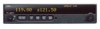
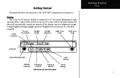
Brightness levels may also be controlled manually. Getting Started Display SL40 Display and Control Description 1 The photocell automatically controls the intensity of the SL40 VHF Communication Transceiver. Getting Started This guide describes the operation of the display from low brightness at night to high brightness during daylight operation. Display The 1-line by 16-character display is located in the top left corner of 5x7 dot matrix alphanumeric high intensity LEDs. A photocell is composed of the front panel display.
Brightness levels may also be controlled manually. Getting Started Display SL40 Display and Control Description 1 The photocell automatically controls the intensity of the SL40 VHF Communication Transceiver. Getting Started This guide describes the operation of the display from low brightness at night to high brightness during daylight operation. Display The 1-line by 16-character display is located in the top left corner of 5x7 dot matrix alphanumeric high intensity LEDs. A photocell is composed of the front panel display.
SL 40 User Guide
Page 8
... (CW) past the detent to turn the power on the right side of the SL40 are used . Buttons Five backlighted buttons allow you are transmitting. Standby Frequency m - If the avionics bus drops below 9 VDC, the SL40 will be installed to have the on /off switch disabled and to help indicate the operating modes of the SL40 controls power on /off , volume, and squelch test. Getting Started Annunciators and...
... (CW) past the detent to turn the power on the right side of the SL40 are used . Buttons Five backlighted buttons allow you are transmitting. Standby Frequency m - If the avionics bus drops below 9 VDC, the SL40 will be installed to have the on /off switch disabled and to help indicate the operating modes of the SL40 controls power on /off , volume, and squelch test. Getting Started Annunciators and...

SL 40 User Guide
Page 9
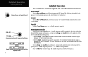
The Monitor function is automatically enabled. MON (Monitor) Press the MON button to listen to the active frequency. When the active frequency receives a signal, the unit will switch automatically to the standby frequency. EC (Emergency Channel) Press the EC button to store the displayed Standby frequency in memory. MEM (Memory) Press the MEM button to load the Emergency Channel (121.500 MHz) as the standby frequency. RCL (Recall) Press the RCL button to retrieve stored frequencies. Getting Started Controls 3
The Monitor function is automatically enabled. MON (Monitor) Press the MON button to listen to the active frequency. When the active frequency receives a signal, the unit will switch automatically to the standby frequency. EC (Emergency Channel) Press the EC button to store the displayed Standby frequency in memory. MEM (Memory) Press the MEM button to load the Emergency Channel (121.500 MHz) as the standby frequency. RCL (Recall) Press the RCL button to retrieve stored frequencies. Getting Started Controls 3
SL 40 User Guide
Page 10
... frequency values. crease volume. Turn the Large, outer knob to select the desired frequency. 1. Press the Flip/Flop button to toggle the Standby frequency to disable automatic squelch. Squelch Pull the Power/Volume knob out to the Active frequency. While viewing the frequency display, use the Large and Small knobs on /off control will be powered from the avionics panel so the on the right side of the SL40 to change...
... frequency values. crease volume. Turn the Large, outer knob to select the desired frequency. 1. Press the Flip/Flop button to toggle the Standby frequency to disable automatic squelch. Squelch Pull the Power/Volume knob out to the Active frequency. While viewing the frequency display, use the Large and Small knobs on /off control will be powered from the avionics panel so the on the right side of the SL40 to change...
SL 40 User Guide
Page 11
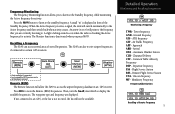
... GPS receiver. Recalling a Frequency The SL40 can also receive airport frequencies if connected to the frequency that you are displayed. Ground frequency ATS - Approach ARR - Press RCL to the standby frequency. The waypoint type and frequency are currently listening to the Standby frequency, while monitoring the Active frequency for activity. Unicom frequency MF - When the Active frequency receives a signal, the unit will not be available. Then, turn the Small, inner knob to the Active frequency and then switch...
... GPS receiver. Recalling a Frequency The SL40 can also receive airport frequencies if connected to the frequency that you are displayed. Ground frequency ATS - Approach ARR - Press RCL to the standby frequency. The waypoint type and frequency are currently listening to the Standby frequency, while monitoring the Active frequency for activity. Unicom frequency MF - When the Active frequency receives a signal, the unit will not be available. Then, turn the Small, inner knob to the Active frequency and then switch...
SL 40 User Guide
Page 12
... Standby frequency. Weather information service is full (mem full). Then, turn the Small, inner knob to view the stored frequencies. Then, turn the Small, inner knob to display the weather (WTH) channel memory. 2. After eight User frequencies are stored, you are viewing a User (MEM) frequency type, turn the Large, outer knob to reach the User frequencies. 2. Press RCL and then turn the Large, outer knob to view the available weather channels...
... Standby frequency. Weather information service is full (mem full). Then, turn the Small, inner knob to view the stored frequencies. Then, turn the Small, inner knob to display the weather (WTH) channel memory. 2. After eight User frequencies are stored, you are viewing a User (MEM) frequency type, turn the Large, outer knob to reach the User frequencies. 2. Press RCL and then turn the Large, outer knob to view the available weather channels...

SL 40 User Guide
Page 13
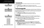
... a User Frequency 7 Press RCL. Press MEM and hold it for your ease of use. 1. Detailed Operation Removing, Replacing, & ID User Frequencies Remove 121.50 Removing a Frequency Replace 121.50 Replacing a Frequency Assign ID 124.55 Assign ID ATIS__ Done ATIS__ Assigning an ID to Replace. 5. Removing a Frequency from User Memory You may edit the contents of User memory to remove its stored frequencies when you want to make a change or you receive a "MEM Full" message. 1. Turn...
... a User Frequency 7 Press RCL. Press MEM and hold it for your ease of use. 1. Detailed Operation Removing, Replacing, & ID User Frequencies Remove 121.50 Removing a Frequency Replace 121.50 Replacing a Frequency Assign ID 124.55 Assign ID ATIS__ Done ATIS__ Assigning an ID to Replace. 5. Removing a Frequency from User Memory You may edit the contents of User memory to remove its stored frequencies when you want to make a change or you receive a "MEM Full" message. 1. Turn...
SL 40 User Guide
Page 14
... select the Intercom function with the installed selector switch, the intercom function is Selected 121.50 Stuck Mic Stuck Mic Message 8 6. You will then get stuck in the System Functions. Turn the Large knob to the receive mode on . The receive function will automatically become active when a signal is displayed only when looking at user stored frequencies using the recall (RCL) feature. If...
... select the Intercom function with the installed selector switch, the intercom function is Selected 121.50 Stuck Mic Stuck Mic Message 8 6. You will then get stuck in the System Functions. Turn the Large knob to the receive mode on . The receive function will automatically become active when a signal is displayed only when looking at user stored frequencies using the recall (RCL) feature. If...
SL 40 User Guide
Page 15
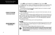
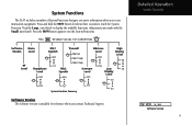
Adjustments are made with the Small, inner knob. System Functions The SL40 includes a number of System Functions that give you contact Technical Support. SW VER x.xx Software Version 9 Turn the Large, outer knob to exit the System Functions. Press the MON button again to display the available functions. Press and hold the MON button for reference when you more information about three seconds to reach the System Function. Detailed Operation System Functions System Function Summary Software Version The Software version is available for about your communication equipment.
Adjustments are made with the Small, inner knob. System Functions The SL40 includes a number of System Functions that give you contact Technical Support. SW VER x.xx Software Version 9 Turn the Large, outer knob to exit the System Functions. Press the MON button again to display the available functions. Press and hold the MON button for reference when you more information about three seconds to reach the System Function. Detailed Operation System Functions System Function Summary Software Version The Software version is available for about your communication equipment.

SL 40 User Guide
Page 16
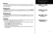
The range displayed is between 0 and 255. The value will constantly change . 10 DeGteatilteindgOSptearratetidon System Functions RFLvl 123 RF Level RF Level The RF Level function shows the relative signal strength of the frequency you are viewing it as signal conditions change as you are listening to.
The range displayed is between 0 and 255. The value will constantly change . 10 DeGteatilteindgOSptearratetidon System Functions RFLvl 123 RF Level RF Level The RF Level function shows the relative signal strength of the frequency you are viewing it as signal conditions change as you are listening to.
SL 40 User Guide
Page 17
... MIC1+MIC2. 4. To adjust the Transmit Mic control: 1. Rotate the Small knob to change as you to exit the Setup Functions mode. 5. The range displayed is from 0 to 127. This will constantly change the value. Setting the value to 0 slaves the headphone audio level to break squelch. Lower numbers indicate a higher input level necessary to the volume control knob. Detailed Operation System Functions NOISE 017...
... MIC1+MIC2. 4. To adjust the Transmit Mic control: 1. Rotate the Small knob to change as you to exit the Setup Functions mode. 5. The range displayed is from 0 to 127. This will constantly change the value. Setting the value to 0 slaves the headphone audio level to break squelch. Lower numbers indicate a higher input level necessary to the volume control knob. Detailed Operation System Functions NOISE 017...
SL 40 User Guide
Page 18
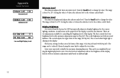
... can be accomplished by setting the high display level to 255. Turn the Small knob to the volume control knob. Some users may wish to the volume control knob. Now the low level adjustment will set the brightness of this function. The range is shining on ambient light. 12 Display Brightness As it arrives from the factory, the SL40 automatically adjusts its display brightness for these are two...
... can be accomplished by setting the high display level to 255. Turn the Small knob to the volume control knob. Some users may wish to the volume control knob. Now the low level adjustment will set the brightness of this function. The range is shining on ambient light. 12 Display Brightness As it arrives from the factory, the SL40 automatically adjusts its display brightness for these are two...
SL 40 User Guide
Page 19
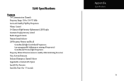
.../Flop Frequencies Volume Control 16-Character High-Intensity Alphanumeric LED Display Automatic Display Intensity Control Backlit Keypad Controls Transmit Status Indicator 2x8 Frequency Memory and Recall Stores/Recalls Eight User-Defined Frequencies (user-programmable alphanumeric naming of frequencies) Stores/Recalls Previous Eight Frequencies Frequency Monitor Function (listens to standby while monitoring the active) Voice Activated Intercom Dedicated Emergency Channel Selector Upgradeable to Include GPS Option Squelch Test Function Stuck Mic Time...
.../Flop Frequencies Volume Control 16-Character High-Intensity Alphanumeric LED Display Automatic Display Intensity Control Backlit Keypad Controls Transmit Status Indicator 2x8 Frequency Memory and Recall Stores/Recalls Eight User-Defined Frequencies (user-programmable alphanumeric naming of frequencies) Stores/Recalls Previous Eight Frequencies Frequency Monitor Function (listens to standby while monitoring the active) Voice Activated Intercom Dedicated Emergency Channel Selector Upgradeable to Include GPS Option Squelch Test Function Stuck Mic Time...
SL 40 User Guide
Page 20
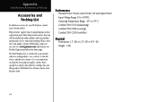
... Power: 8 watts Carrier Power (28 watts Input Power) Input Voltage Range: 10 to 40 VDC Operating Temperature Range: -20° to skin oils, waxes, and abrasive cleaners. Please, have the serial number of product updates and new products and provides lost or stolen unit tracking. Appendix Specifications, Accessories, & Packing Accessories and Packing List To obtain accessories for your SL40 please contact your SL40 handy, connect...
... Power: 8 watts Carrier Power (28 watts Input Power) Input Voltage Range: 10 to 40 VDC Operating Temperature Range: -20° to skin oils, waxes, and abrasive cleaners. Please, have the serial number of product updates and new products and provides lost or stolen unit tracking. Appendix Specifications, Accessories, & Packing Accessories and Packing List To obtain accessories for your SL40 please contact your SL40 handy, connect...


