
Installation Manual
Page 2
...: 913-397-8200 Aviation Dealer Technical Support Line (Toll Free): (888) 606-5482 www.garmin.com Garmin (Europe) Ltd Liberty House Bulls Copse Road Hounsdown Business Park Southampton, SO40 9RB, UK Telephone: +44 (0) 8708501241 Revision Date 6/29/12 8/14/12 10/22/12 RECORD OF REVISIONS Description Production Release Added operation instructions section Added antenna part numbers and antenna installation instructions 190-00829-01...
...: 913-397-8200 Aviation Dealer Technical Support Line (Toll Free): (888) 606-5482 www.garmin.com Garmin (Europe) Ltd Liberty House Bulls Copse Road Hounsdown Business Park Southampton, SO40 9RB, UK Telephone: +44 (0) 8708501241 Revision Date 6/29/12 8/14/12 10/22/12 RECORD OF REVISIONS Description Production Release Added operation instructions section Added antenna part numbers and antenna installation instructions 190-00829-01...
Installation Manual
Page 3
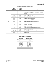
... - 5-6 B-2 Section Number 1.1 2.2 2.2.2 3.4.1 3.4.2 3.5 3.5.3 3.5.4 4.2.2 5.1 5.2.1 5.2.1 5.2.3 B.2 Description of Change Added standard introduction Added GWX 70 and Antenna part numbers, reformatted table Added config module note Expanded installation instructions Expanded mounting instructions Added reference to GWX 68 procedures Added reference to GWX 68 procedures Added reference to GWX 68 procedures Corrected pin number Added COM port note Added downloading and installing instructions Added normal mode note Expanded CFG Data Tab explanation Correct pinout DOCUMENT PAGINATION Section...
... - 5-6 B-2 Section Number 1.1 2.2 2.2.2 3.4.1 3.4.2 3.5 3.5.3 3.5.4 4.2.2 5.1 5.2.1 5.2.1 5.2.3 B.2 Description of Change Added standard introduction Added GWX 70 and Antenna part numbers, reformatted table Added config module note Expanded installation instructions Expanded mounting instructions Added reference to GWX 68 procedures Added reference to GWX 68 procedures Added reference to GWX 68 procedures Corrected pin number Added COM port note Added downloading and installing instructions Added normal mode note Expanded CFG Data Tab explanation Correct pinout DOCUMENT PAGINATION Section...

Installation Manual
Page 7
... USE THE PRODUCT OR FROM DEFECTS IN THE PRODUCT. Devices purchased in the United States or Canada must be made at its sole discretion. Bulls Copse Road Phone: 800/800.1020 Hounsdown Business Park FAX: 913/397.0836 Southampton, SO40 9RB, UK Telephone: 44 (0) 8708501241 190-00829-01 Rev. C GWX 70 Installation Manual Page v Such repairs or replacement will not replace...
... USE THE PRODUCT OR FROM DEFECTS IN THE PRODUCT. Devices purchased in the United States or Canada must be made at its sole discretion. Bulls Copse Road Phone: 800/800.1020 Hounsdown Business Park FAX: 913/397.0836 Southampton, SO40 9RB, UK Telephone: 44 (0) 8708501241 190-00829-01 Rev. C GWX 70 Installation Manual Page v Such repairs or replacement will not replace...
Installation Manual
Page 8
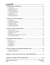
... Operating Instructions ...1-7 1.8 Reference Documents...1-11 2 INSTALLATION OVERVIEW 2-1 2.1 Introduction ...2-1 2.2 Installation Materials ...2-1 2.3 Installation Considerations 2-3 2.4 Cabling & Wiring ...2-4 2.5 Cooling Requirements ...2-4 2.6 Mounting Requirements 2-4 3 INSTALLATION PROCEDURE 3-1 3.1 Unpacking Unit...3-1 3.2 Wiring Harness Installation 3-2 3.3 Backshell Assembly ...3-3 3.4 Installation ...3-4 3.5 Post Installation Configuration & Checkout 3-12 3.6 Continued Airworthiness 3-13 4 SYSTEM INTERCONNECTS 4-1 4.1 Pin List...4-1 4.2 Power Functions ...4-4 4.3 Serial Data...
... Operating Instructions ...1-7 1.8 Reference Documents...1-11 2 INSTALLATION OVERVIEW 2-1 2.1 Introduction ...2-1 2.2 Installation Materials ...2-1 2.3 Installation Considerations 2-3 2.4 Cabling & Wiring ...2-4 2.5 Cooling Requirements ...2-4 2.6 Mounting Requirements 2-4 3 INSTALLATION PROCEDURE 3-1 3.1 Unpacking Unit...3-1 3.2 Wiring Harness Installation 3-2 3.3 Backshell Assembly ...3-3 3.4 Installation ...3-4 3.5 Post Installation Configuration & Checkout 3-12 3.6 Continued Airworthiness 3-13 4 SYSTEM INTERCONNECTS 4-1 4.1 Pin List...4-1 4.2 Power Functions ...4-4 4.3 Serial Data...
Installation Manual
Page 9
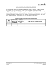
...) and is current at www.garmin.com using their Garmin-provided user name and password. C GWX 70 Installation Manual Page vii GWX 70 HARDWARE MOD LEVEL HISTORY The following table identifies hardware modification (Mod) Levels for the GWX 70. Mod Levels are encouraged to access the most up-to change without notice. Authorized Garmin Sales and Service Centers are listed with the associated service bulletin number, service bulletin date, and the purpose...
...) and is current at www.garmin.com using their Garmin-provided user name and password. C GWX 70 Installation Manual Page vii GWX 70 HARDWARE MOD LEVEL HISTORY The following table identifies hardware modification (Mod) Levels for the GWX 70. Mod Levels are encouraged to access the most up-to change without notice. Authorized Garmin Sales and Service Centers are listed with the associated service bulletin number, service bulletin date, and the purpose...
Installation Manual
Page 11
... to install equipment by reference to this manual assumes use in the planning and design of an installation of the Garmin GWX 70 Weather Radar into an aircraft. 1 GENERAL DESCRIPTION 1.1 Introduction This manual is intended to provide mechanical and electrical information for use by competent and qualified avionics engineering personnel and/or avionics installation specialists using standard aviation maintenance practices in accordance with Title 14 of the Code of...
... to install equipment by reference to this manual assumes use in the planning and design of an installation of the Garmin GWX 70 Weather Radar into an aircraft. 1 GENERAL DESCRIPTION 1.1 Introduction This manual is intended to provide mechanical and electrical information for use by competent and qualified avionics engineering personnel and/or avionics installation specialists using standard aviation maintenance practices in accordance with Title 14 of the Code of...
Installation Manual
Page 12
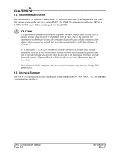
..., can disrupt GPS performance. 1.3 Interface Summary The GWX 70 is designed as an open architecture system that is on board that outputs weather radar data to FAA regulations 14 CFR 91.21. When any aircraft while the aircraft is off . 1.2 Equipment Description The Garmin GWX 70 Airborne Weather Radar is a microprocessor-based Line Replaceable Unit (LRU) that aircraft must not be turned off the ground. GWX 70 Installation Manual Page 1-2 190...
..., can disrupt GPS performance. 1.3 Interface Summary The GWX 70 is designed as an open architecture system that is on board that outputs weather radar data to FAA regulations 14 CFR 91.21. When any aircraft while the aircraft is off . 1.2 Equipment Description The Garmin GWX 70 Airborne Weather Radar is a microprocessor-based Line Replaceable Unit (LRU) that aircraft must not be turned off the ground. GWX 70 Installation Manual Page 1-2 190...

Installation Manual
Page 13
... GWX 70 18" Installation Kit (011-01769-01)** 2.9 lbs * This weight includes all mounting hardware required to mount the 10" and 12"assembly to the aircraft. ** This weight includes all mounting hardware required to mount the 18" assembly to obtain the latest revision of the GWX 70 Environmental Qualification Form. 1.4 Technical Specifications It is available directly from Garmin under the following part number: GWX 70 Environmental Qualification Form, Garmin part number 005...
... GWX 70 18" Installation Kit (011-01769-01)** 2.9 lbs * This weight includes all mounting hardware required to mount the 10" and 12"assembly to the aircraft. ** This weight includes all mounting hardware required to mount the 18" assembly to obtain the latest revision of the GWX 70 Environmental Qualification Form. 1.4 Technical Specifications It is available directly from Garmin under the following part number: GWX 70 Environmental Qualification Form, Garmin part number 005...

Installation Manual
Page 15
... meet federal communications commission acceptance over the operating temperature range. Modifications not expressly approved by fax. The GWX 70 owner accepts all responsibility for Aircraft Radio Station License. Characteristic STC Extended STC Table 1-3. GWX 70 Performance Specifications Specification Effective to 40nm 40nm to 320nm 1.4.4 Power Specifications Table 1-4. To find out the specific details on FCC form 404, Application for obtaining the proper licensing before using the GWX 70.
... meet federal communications commission acceptance over the operating temperature range. Modifications not expressly approved by fax. The GWX 70 owner accepts all responsibility for Aircraft Radio Station License. Characteristic STC Extended STC Table 1-3. GWX 70 Performance Specifications Specification Effective to 40nm 40nm to 320nm 1.4.4 Power Specifications Table 1-4. To find out the specific details on FCC form 404, Application for obtaining the proper licensing before using the GWX 70.

Installation Manual
Page 17
... is always a good idea to put the radar in the Weather or Ground Map mode, the system automatically switches to applicable airframe specific documentation for instructions on landing. C GWX 70 Installation Manual Page 1-7 The system displays a horizontal scan. If the aircraft is green, off when gray. 3. 1.7 Operating Instructions This section contains generic operating instructions for TSO purposes only and is not to the radar assembly. When the...
... is always a good idea to put the radar in the Weather or Ground Map mode, the system automatically switches to applicable airframe specific documentation for instructions on landing. C GWX 70 Installation Manual Page 1-7 The system displays a horizontal scan. If the aircraft is green, off when gray. 3. 1.7 Operating Instructions This section contains generic operating instructions for TSO purposes only and is not to the radar assembly. When the...
Installation Manual
Page 18
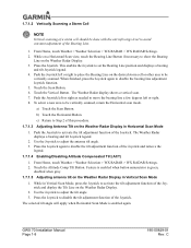
... Bearing Line. 1. GWX 70 Installation Manual Page 1-8 190-00829-01 Rev. To select a new area to be done with the aircraft wings level to disable the tilt adjustment function of the Joystick. Push the Joystick to adjust the tilt angle. 3. Use the Joystick to activate the tilt adjustment function of the Joystick and remove the legend. 1.7.1.4 Enabling/Disabling Altitude Compensated Tilt (ACT...
... Bearing Line. 1. GWX 70 Installation Manual Page 1-8 190-00829-01 Rev. To select a new area to be done with the aircraft wings level to disable the tilt adjustment function of the Joystick. Push the Joystick to adjust the tilt angle. 3. Use the Joystick to activate the tilt adjustment function of the Joystick and remove the legend. 1.7.1.4 Enabling/Disabling Altitude Compensated Tilt (ACT...

Installation Manual
Page 21
GWX 70 Reference Documents Part Number 190-00303-00 560-1025-09 190-00607-04 190-00313-11 Document G1000 System Installation Manual MX20 MFD Installation Manual GMX 200 Installation Manual Jackscrew Backshell Installation Instructions 190-00829-01 Rev. C GWX 70 Installation Manual Page 1-11 Table 1-7. 1.8 Reference Documents The following publications are sources of additional information for installing the GWX 70. Before installing the unit, the technician should read all relevant referenced materials along with this manual.
GWX 70 Reference Documents Part Number 190-00303-00 560-1025-09 190-00607-04 190-00313-11 Document G1000 System Installation Manual MX20 MFD Installation Manual GMX 200 Installation Manual Jackscrew Backshell Installation Instructions 190-00829-01 Rev. C GWX 70 Installation Manual Page 1-11 Table 1-7. 1.8 Reference Documents The following publications are sources of additional information for installing the GWX 70. Before installing the unit, the technician should read all relevant referenced materials along with this manual.
Installation Manual
Page 23
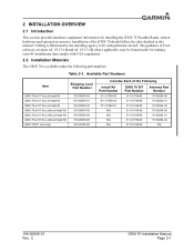
... found useful for installing the GWX 70 Weather Radar, related hardware and optional accessories. C GWX 70 Installation Manual Page 2-1 Cabling is available under the following part numbers. The guidance of the Following Install Kit Part Number 011-01769-00 011-01769-00 011-01769-01 N/A N/A N/A N/A GWX 70 R/T Part Number 011-01768-00 011-01768-00 011-01768-00 011-01768-00 011-01768-00 011-01768-00 011-01768-00 Antenna Part Number...
... found useful for installing the GWX 70 Weather Radar, related hardware and optional accessories. C GWX 70 Installation Manual Page 2-1 Cabling is available under the following part numbers. The guidance of the Following Install Kit Part Number 011-01769-00 011-01769-00 011-01769-01 N/A N/A N/A N/A GWX 70 R/T Part Number 011-01768-00 011-01768-00 011-01768-00 011-01768-00 011-01768-00 011-01768-00 011-01768-00 Antenna Part Number...
Installation Manual
Page 26
... the aircraft to minimize radiated EMI and provide protection from High-Intensity Radiation Fields (HIRF). Limiting thermal build up, by adjacent equipment. This minimizes the risk of #18 or #20 AWG wire for power connections, the provided connector kit supplies extended barrel contacts for wire gauge guidance. C GWX 70 Installation Manual Page 2-4 190-00829-01 Rev. Use wire and cable meeting the applicable aviation regulation. 2.4 Cabling & Wiring Refer...
... the aircraft to minimize radiated EMI and provide protection from High-Intensity Radiation Fields (HIRF). Limiting thermal build up, by adjacent equipment. This minimizes the risk of #18 or #20 AWG wire for power connections, the provided connector kit supplies extended barrel contacts for wire gauge guidance. C GWX 70 Installation Manual Page 2-4 190-00829-01 Rev. Use wire and cable meeting the applicable aviation regulation. 2.4 Cabling & Wiring Refer...

Installation Manual
Page 28
... M81969/1-04 GWX 70 Installation Manual Page 3-2 190-00829-01 Rev. All electrical connections to the Jackscrew Backshell Installation Instructions (190-00313-11) for interfacial seal installation instructions. C Table 3-1. The installer shall supply and fabricate all input and output signals. NOTE An interfacial seal is required with the aircraft manufacturer authorized interconnect standards. See Appendix B for examples of cables and connectors. Required connectors and associated hardware are made...
... M81969/1-04 GWX 70 Installation Manual Page 3-2 190-00829-01 Rev. All electrical connections to the Jackscrew Backshell Installation Instructions (190-00313-11) for interfacial seal installation instructions. C Table 3-1. The installer shall supply and fabricate all input and output signals. NOTE An interfacial seal is required with the aircraft manufacturer authorized interconnect standards. See Appendix B for examples of cables and connectors. Required connectors and associated hardware are made...
Installation Manual
Page 29
... subject to the Jackscrew Backshell Installation Instructions (190-00313-11) and the Jackscrew Configuration Module Installation Instructions (190-00313-10) for assembly instructions. 190-00829-01 Rev. It may also be used when reassembling the connector. 3.3 Backshell Assembly The GWX 70 connector kits (011-01769-00 and 011-01769-01) include one Garmin backshell assembly. Refer to change without notice. 2. C GWX 70 Installation Manual Page 3-3 A new contact must be...
... subject to the Jackscrew Backshell Installation Instructions (190-00313-11) and the Jackscrew Configuration Module Installation Instructions (190-00313-10) for assembly instructions. 190-00829-01 Rev. It may also be used when reassembling the connector. 3.3 Backshell Assembly The GWX 70 connector kits (011-01769-00 and 011-01769-01) include one Garmin backshell assembly. Refer to change without notice. 2. C GWX 70 Installation Manual Page 3-3 A new contact must be...

Installation Manual
Page 38
...adjacent to the GWX 70 from an aircraft-specific GX000 Software Loader Card. For GWX 70 installations operating with a Garmin GMX 200, refer to the GWX 68/MX20 unit configuration instructions in normal operating mode. Always use aircraft manufacturer approved checkout documents when performing actual checkouts. For GWX 70 installations operating with a Garmin MX20, refer to the GWX 68/GMX 200 unit configuration instructions in a straight and level attitude as the graphics user interface to the G1000 Line Maintenance Manual and Configuration Manual, Garmin part number 190-00303-04...
...adjacent to the GWX 70 from an aircraft-specific GX000 Software Loader Card. For GWX 70 installations operating with a Garmin GMX 200, refer to the GWX 68/MX20 unit configuration instructions in normal operating mode. Always use aircraft manufacturer approved checkout documents when performing actual checkouts. For GWX 70 installations operating with a Garmin MX20, refer to the GWX 68/GMX 200 unit configuration instructions in a straight and level attitude as the graphics user interface to the G1000 Line Maintenance Manual and Configuration Manual, Garmin part number 190-00303-04...

Installation Manual
Page 39
.... As you change a value the window will now restart. 3.5.2 G2000, G3000, G5000/GWX 70 Pitch and Roll Trim Adjustments Pitch and Roll Trim adjustments procedures are dependent upon OEM specifications. Contact Garmin Product Support. 3.5.3 MX20/GWX 70 Pitch and Roll Trim Adjustments For instructions on MX20/GWX 70 pitch and roll trim adjustments refer to the GWX 68 pitch and roll trim adjustment procedures located in the MX20 Installation Manual (560...
.... As you change a value the window will now restart. 3.5.2 G2000, G3000, G5000/GWX 70 Pitch and Roll Trim Adjustments Pitch and Roll Trim adjustments procedures are dependent upon OEM specifications. Contact Garmin Product Support. 3.5.3 MX20/GWX 70 Pitch and Roll Trim Adjustments For instructions on MX20/GWX 70 pitch and roll trim adjustments refer to the GWX 68 pitch and roll trim adjustment procedures located in the MX20 Installation Manual (560...

Installation Manual
Page 48
...High Low High Low Antenna Size Antenna size set by software configuration 10" Antenna 12" Antenna 18" Antenna GWX 70 Installation Manual Page 4-8 190-00829-01 Rev. Antenna Select Connector Pin I /O 60 Out 4.5 Configuration 4.5.1 Antenna Select Pin Name ANTENNA SELECT* 0 ANTENNA SELECT* 1 Table 4-9. Table 4-10. NOTE The antenna select inputs should be left unconnected (floating high) in GX000 installations. C Configuration Module Pin Name CONFIG MODULE POWER CONFIG MODULE GROUND CONFIG MODULE DATA CONFIG MODULE CLOCK Connector P751 P751 P751 P751 Pin I/O 24 Out 43...
...High Low High Low Antenna Size Antenna size set by software configuration 10" Antenna 12" Antenna 18" Antenna GWX 70 Installation Manual Page 4-8 190-00829-01 Rev. Antenna Select Connector Pin I /O 60 Out 4.5 Configuration 4.5.1 Antenna Select Pin Name ANTENNA SELECT* 0 ANTENNA SELECT* 1 Table 4-9. Table 4-10. NOTE The antenna select inputs should be left unconnected (floating high) in GX000 installations. C Configuration Module Pin Name CONFIG MODULE POWER CONFIG MODULE GROUND CONFIG MODULE DATA CONFIG MODULE CLOCK Connector P751 P751 P751 P751 Pin I/O 24 Out 43...
Installation Manual
Page 53
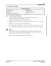
... with 32-bit Windows versions select the "Install tool installer 32-bit.msi" file. NOTE The installation will be canceled if the installation file and the operating system do not match. 5.2 Program Information Program Archive File Name Version at time of www.garmin.com find and save the "006-A0436-00.zip" file from the website to install the GWX 70 Install Tool. 190-00829-01 Rev.
... with 32-bit Windows versions select the "Install tool installer 32-bit.msi" file. NOTE The installation will be canceled if the installation file and the operating system do not match. 5.2 Program Information Program Archive File Name Version at time of www.garmin.com find and save the "006-A0436-00.zip" file from the website to install the GWX 70 Install Tool. 190-00829-01 Rev.

