
GTR 200 Installation Manual
Page 16
...the transceiver. Outside the US, contact the responsible telecommunication authority. The GTR owner accepts all responsibility for Aircraft Radio Station License. GTR 200 Installation Manual Page 1-4 190-01553-00 Rev. GTR installations must comply with manual override 1.3.5 License Requirements The Telecommunications Act of...FCC web site http://wireless.fcc.gov/aviation. The GTR 200 receiver meets the requirements of RTCA DO-186B section 2.2 for licensing and are detailed in Section 1.3.4. 1.3.6 Aircraft Radio An aircraft radio station license is not required when operating in U.S. ...
...the transceiver. Outside the US, contact the responsible telecommunication authority. The GTR owner accepts all responsibility for Aircraft Radio Station License. GTR 200 Installation Manual Page 1-4 190-01553-00 Rev. GTR installations must comply with manual override 1.3.5 License Requirements The Telecommunications Act of...FCC web site http://wireless.fcc.gov/aviation. The GTR 200 receiver meets the requirements of RTCA DO-186B section 2.2 for licensing and are detailed in Section 1.3.4. 1.3.6 Aircraft Radio An aircraft radio station license is not required when operating in U.S. ...

GTR 200 Installation Manual
Page 20
... aviation regulations should be used. 2.5 Antenna Considerations This section contains mounting location considerations for the antennas required for maximum isolation. The GTR 200 requires a transmit interlock. The ground plane surface directly below the antenna should be a flat plane over as large an area as... practical from the signal coming in on the ELT antenna coax. If simultaneous use with other radios, including GPS. GTR 200 Installation Manual Page 2-2 190-01553-00 Rev. The COM antenna should be mounted as far as possible (18 inch square...
... aviation regulations should be used. 2.5 Antenna Considerations This section contains mounting location considerations for the antennas required for maximum isolation. The GTR 200 requires a transmit interlock. The ground plane surface directly below the antenna should be a flat plane over as large an area as... practical from the signal coming in on the ELT antenna coax. If simultaneous use with other radios, including GPS. GTR 200 Installation Manual Page 2-2 190-01553-00 Rev. The COM antenna should be mounted as far as possible (18 inch square...

GTR 200 Installation Manual
Page 21
...chosen that type, are required to ensure good coax ground. • Place a grounding brace between the GTR 200 and ground. • Shield the GTR 200 wiring harness. 190-01553-00 Rev. A GTR 200 Installation Manual Page 2-3 Use the following guidelines, in addition to others in this document, when locating ...If a COM is critical. A COM Antenna that necessary for successful communication. To reduce potential radio interference to other users, the antenna type and its antenna. • Locate the GTR 200 as far as possible from all GPS antennas. • Locate the COM antenna as far as...
...chosen that type, are required to ensure good coax ground. • Place a grounding brace between the GTR 200 and ground. • Shield the GTR 200 wiring harness. 190-01553-00 Rev. A GTR 200 Installation Manual Page 2-3 Use the following guidelines, in addition to others in this document, when locating ...If a COM is critical. A COM Antenna that necessary for successful communication. To reduce potential radio interference to other users, the antenna type and its antenna. • Locate the GTR 200 as far as possible from all GPS antennas. • Locate the COM antenna as far as...

GTR 200 Installation Manual
Page 25
...Route the COM antenna cable as far as possible. A GTR 200 Installation Manual Page 3-3 Follow the BNC connector manufacturer's instructions for mounting the antenna. Check for the cabling and mating connectors. The VSWR meter should be provisioned by the radio when the radio is performed in the coaxial transmission line between the transceiver... and Voltage Standing Wave Ratio (VSWR). A VSWR of 18 inches x 18 inches. Avoid sharp bends in transmit power. 3.5 Antenna Installation and Connections The GTR 200 requires a standard 50 vertically polarized antenna.
...Route the COM antenna cable as far as possible. A GTR 200 Installation Manual Page 3-3 Follow the BNC connector manufacturer's instructions for mounting the antenna. Check for the cabling and mating connectors. The VSWR meter should be provisioned by the radio when the radio is performed in the coaxial transmission line between the transceiver... and Voltage Standing Wave Ratio (VSWR). A VSWR of 18 inches x 18 inches. Avoid sharp bends in transmit power. 3.5 Antenna Installation and Connections The GTR 200 requires a standard 50 vertically polarized antenna.

GTR 200 Installation Manual
Page 32
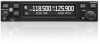
... has been changed, turn the LARGE Knob to move the cursor to select the Softkey Setup Page. MUSIC ON/OFF* Turns music input on/off GTR 200 Installation Manual Page 3-10 190-01553-00 Rev. Note that function is not available when the intercom is set to off . A Refer to Section 3.6.4 to... listed in Table 3-6. Use the LARGE Knob to scroll through the listed functions, then use the SMALL Knob to user frequency list menu. PILOT PTT Radio transmits pilot MIC audio when key pressed.
... has been changed, turn the LARGE Knob to move the cursor to select the Softkey Setup Page. MUSIC ON/OFF* Turns music input on/off GTR 200 Installation Manual Page 3-10 190-01553-00 Rev. Note that function is not available when the intercom is set to off . A Refer to Section 3.6.4 to... listed in Table 3-6. Use the LARGE Knob to scroll through the listed functions, then use the SMALL Knob to user frequency list menu. PILOT PTT Radio transmits pilot MIC audio when key pressed.
GTR 200 Installation Manual
Page 37
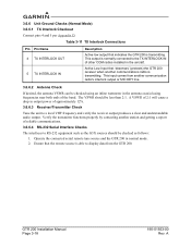
...page (Figure 3-12) allows the installer to test the operation of this test. 10. Indicates the radio is overridden. Indicates the radio squelch is receiving. d) LO VOLT - When the GTR 200 is safe for transmission. Correct this condition before attempting to transmit. 8. Select a frequency that is ... not check there is supplied to select the COM Tests Page. f) TX AMPS - The radio will be performed as part of the COM functions. When the GTR 200 is preventing the radio from receiving proper voltage. If the LO VOLT checkbox is checked this test. 5. Select a...
...page (Figure 3-12) allows the installer to test the operation of this test. 10. Indicates the radio is overridden. Indicates the radio squelch is receiving. d) LO VOLT - When the GTR 200 is safe for transmission. Correct this condition before attempting to transmit. 8. Select a frequency that is ... not check there is supplied to select the COM Tests Page. f) TX AMPS - The radio will be performed as part of the COM functions. When the GTR 200 is preventing the radio from receiving proper voltage. If the LO VOLT checkbox is checked this test. 5. Select a...
GTR 200 Installation Manual
Page 40
...remote source is transmitting. Ensure that 'desenses' (protects) the GTR 200 receiver when another communications radio is able to display data from another station and getting a report of other COM radios installed in normal mode. 2. GTR 200 Installation Manual Page 3-18 190-01553-00 Rev. This input... comes from the GTR 200. A A VSWR of 2:1 will cause a drop in the antenna coaxial using ...
...remote source is transmitting. Ensure that 'desenses' (protects) the GTR 200 receiver when another communications radio is able to display data from another station and getting a report of other COM radios installed in normal mode. 2. GTR 200 Installation Manual Page 3-18 190-01553-00 Rev. This input... comes from the GTR 200. A A VSWR of 2:1 will cause a drop in the antenna coaxial using ...

GTR 200 Installation Manual
Page 49
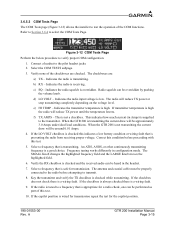
... Interlock In is considered inactive if the voltage to ground is 6.5-33 VDC or the resistance to ground is an active low input that this radio's (GTR 200) COM is >100 k. Pin Name Pin I /O 2 In 22 In 190-01553-00 Rev. Active-Low discrete inputs are configurable. TX ...INTERLOCK OUT will sink 20mA of current and will output a voltage of 1V or less. TX Interlock In is >100 k. A GTR 200 Installation Manual Page 4-5 These inputs are considered inactive if the voltage to ground is 6.5-33 VDC or the resistance to ground is transmitting. These inputs...
... Interlock In is considered inactive if the voltage to ground is 6.5-33 VDC or the resistance to ground is an active low input that this radio's (GTR 200) COM is >100 k. Pin Name Pin I /O 2 In 22 In 190-01553-00 Rev. Active-Low discrete inputs are configurable. TX ...INTERLOCK OUT will sink 20mA of current and will output a voltage of 1V or less. TX Interlock In is >100 k. A GTR 200 Installation Manual Page 4-5 These inputs are considered inactive if the voltage to ground is 6.5-33 VDC or the resistance to ground is transmitting. These inputs...

GTR 200 Installation Manual
Page 71
... 2. POWER AND GROUND WIRES MUST BE 20 AWG 4. THE GTR 200 IS CONNECTED AS COM 2. *DENOTES AN ACTIVE LOW SIGNAL. 14. IF TWO COM RADIOS ARE INSTALLED THIS INPUT AND OUTPUT CONNECTS TO THE OTHER COM RADIO. *TRANSMIT INTERLOCK IN TO *TRANSMIT INTERLOCK OUT AND *TRANSMIT ...NOTED, ALL WIRES ARE 22 AWG MINIMUM. ISOLATE JACK SLEEVE (MOUNTING NUT AND NUT PLATE) FROM AIRCRAFT CHASSIS. 6. Figure D-1 GTR 200 Interconnect Example Notes GTR 200 Installation Manual Page D-1 LIGHTING BUS VOLTAGE RANGE IS CONFIGURABLE. 11. THE INTERCONNECT WIRE SHIELD PROVIDES THE RS-232 GROUND CONNECTION. ...
... 2. POWER AND GROUND WIRES MUST BE 20 AWG 4. THE GTR 200 IS CONNECTED AS COM 2. *DENOTES AN ACTIVE LOW SIGNAL. 14. IF TWO COM RADIOS ARE INSTALLED THIS INPUT AND OUTPUT CONNECTS TO THE OTHER COM RADIO. *TRANSMIT INTERLOCK IN TO *TRANSMIT INTERLOCK OUT AND *TRANSMIT ...NOTED, ALL WIRES ARE 22 AWG MINIMUM. ISOLATE JACK SLEEVE (MOUNTING NUT AND NUT PLATE) FROM AIRCRAFT CHASSIS. 6. Figure D-1 GTR 200 Interconnect Example Notes GTR 200 Installation Manual Page D-1 LIGHTING BUS VOLTAGE RANGE IS CONFIGURABLE. 11. THE INTERCONNECT WIRE SHIELD PROVIDES THE RS-232 GROUND CONNECTION. ...

GTR 200 Pilot's Guide
Page 6
...less than the affected special anti-reflective coating which is very equipment. This notice is being provided in a particular tracking. contact Garmin. Operation of product updates and new Furthermore, there is encouraged to try page. notified of this device is subject to the ...to the State of 26 cm from the antenna should be interference to radio Communications. NOTE: Canadian installations: In accordance with the instructions, may cause undesired operation. with Canadian Radio Specifications Standard 102 (RSS 102), an RF safety separation distance of California ...
...less than the affected special anti-reflective coating which is very equipment. This notice is being provided in a particular tracking. contact Garmin. Operation of product updates and new Furthermore, there is encouraged to try page. notified of this device is subject to the ...to the State of 26 cm from the antenna should be interference to radio Communications. NOTE: Canadian installations: In accordance with the instructions, may cause undesired operation. with Canadian Radio Specifications Standard 102 (RSS 102), an RF safety separation distance of California ...

GTR 200 Pilot's Guide
Page 9
TABLE OF CONTENTS DESCRIPTION...1 Display ...1 Controls...2 Softkeys...3 BASIC OPERATION...4 Power-UP...4 COM Radio...4 Selecting a COM Frequency 4 Adjusting Volume 4 Standby COM Frequency Monitoring 5 Monitoring the Standby COM Frequency 5 COM Frequency Storage 5 Saving a COM Frequency 5 Editing a Saved COM Frequency 6 Accessing ...
TABLE OF CONTENTS DESCRIPTION...1 Display ...1 Controls...2 Softkeys...3 BASIC OPERATION...4 Power-UP...4 COM Radio...4 Selecting a COM Frequency 4 Adjusting Volume 4 Standby COM Frequency Monitoring 5 Monitoring the Standby COM Frequency 5 COM Frequency Storage 5 Saving a COM Frequency 5 Editing a Saved COM Frequency 6 Accessing ...

GTR 200 Pilot's Guide
Page 12
...to return to the Active frequency. 2 Garmin GTR 200 Pilot's Guide 190-01553-01 Rev. Switching between the active (left-most) and standby (right-most) frequency. Softkeys MicroSD™ Card Slot Frequency Transfer Key Monitor Standby Frequency Key To override the radio receiver automatic squelch, press the Power/ ...to the left of the active COM frequency window in the upper left corner of the bezel controls audio volume for the COM radio. GTR 200 CONTROLS Control Menu Button Power/ Volume/ Squelch Knob Description Press to view Menu options on and counter-clockwise turns power off. You...
...to return to the Active frequency. 2 Garmin GTR 200 Pilot's Guide 190-01553-01 Rev. Switching between the active (left-most) and standby (right-most) frequency. Softkeys MicroSD™ Card Slot Frequency Transfer Key Monitor Standby Frequency Key To override the radio receiver automatic squelch, press the Power/ ...to the left of the active COM frequency window in the upper left corner of the bezel controls audio volume for the COM radio. GTR 200 CONTROLS Control Menu Button Power/ Volume/ Squelch Knob Description Press to view Menu options on and counter-clockwise turns power off. You...
GTR 200 Pilot's Guide
Page 14
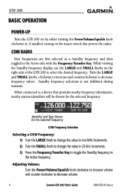
... Frequency Transfer Key to toggle the Standby frequency to the Active frequency. A COM RADIO New frequencies are first selected as a Standby frequency and then toggled to a device that powers the radios. Standby frequency selections is not inhibited during transmit. When connected to the Active side... knob clockwise or, if installed, turning on the right side of the GTR 200 to select the desired frequency. Turn the LARGE and SMALL knobs, clockwise to increase and counterclockwise to decrease volume. 4 Garmin GTR 200 Pilot's Guide 190-01553-01 Rev. Identifier and Type Shown for the...
... Frequency Transfer Key to toggle the Standby frequency to the Active frequency. A COM RADIO New frequencies are first selected as a Standby frequency and then toggled to a device that powers the radios. Standby frequency selections is not inhibited during transmit. When connected to the Active side... knob clockwise or, if installed, turning on the right side of the GTR 200 to select the desired frequency. Turn the LARGE and SMALL knobs, clockwise to increase and counterclockwise to decrease volume. 4 Garmin GTR 200 Pilot's Guide 190-01553-01 Rev. Identifier and Type Shown for the...

GTR 200 Pilot's Guide
Page 25
... are provided as an aid in the pressed position for at least 30 seconds. This key will now be ignored. A Garmin GTR 200 Pilot's Guide 15 This key will now be ignored. Contact Garmin for at least 30 seconds. The key has been in the pressed position for service if this message persists. Action... power connections Check Mic key input connection Check connections. Message VOLUME KEY IS STUCK SOFTKEY #1 IS STUCK Description The key has been in troubleshooting the radio functions.
... are provided as an aid in the pressed position for at least 30 seconds. This key will now be ignored. A Garmin GTR 200 Pilot's Guide 15 This key will now be ignored. Contact Garmin for at least 30 seconds. The key has been in the pressed position for service if this message persists. Action... power connections Check Mic key input connection Check connections. Message VOLUME KEY IS STUCK SOFTKEY #1 IS STUCK Description The key has been in troubleshooting the radio functions.
