
GTR 200 Installation Manual
Page 7
...Mounting Considerations 2-4 2.7 Cabling and Wiring...2-4 2.8 Air Circulation and Cooling 2-4 2.9 Compass Safe Distance...2-4 Section 3 Installation Procedures 3-1 3.1 Unpacking the unit...3-1 3.2 Wiring Harness Installation 3-1 3.3 Backshell Assembly...3-2 3.4 Mounting Requirements 3-2 3.5 Antenna Installation and Connections 3-3 3.6 Post Installation Configuration and Checkout Procedures 3-4 3.7 Unit Software ...3-20 3.8 Continued... Audio ...4-4 4.9 Pilot/Copilot PTT Inputs 4-5 4.10 TX Interlock...4-5 4.11 Discrete Inputs ...4-5 190-01553-00 Rev. A GTR 200 Installation Manual Page v
...Mounting Considerations 2-4 2.7 Cabling and Wiring...2-4 2.8 Air Circulation and Cooling 2-4 2.9 Compass Safe Distance...2-4 Section 3 Installation Procedures 3-1 3.1 Unpacking the unit...3-1 3.2 Wiring Harness Installation 3-1 3.3 Backshell Assembly...3-2 3.4 Mounting Requirements 3-2 3.5 Antenna Installation and Connections 3-3 3.6 Post Installation Configuration and Checkout Procedures 3-4 3.7 Unit Software ...3-20 3.8 Continued... Audio ...4-4 4.9 Pilot/Copilot PTT Inputs 4-5 4.10 TX Interlock...4-5 4.11 Discrete Inputs ...4-5 190-01553-00 Rev. A GTR 200 Installation Manual Page v

GTR 200 Installation Manual
Page 21
...in this device. Placement of the GPS antenna relative to a COM transceiver and COM antenna (including the GTR/ COM antenna), ELT antenna, and DF receiver antenna is critical. The GTR 200 has been approved by Industry Canada. Use the following can re-radiate to the GPS antenna. If ...be done: • Replace or clean VHF COM rack connector to ensure good coax ground. • Place a grounding brace between the GTR 200 and ground. • Shield the GTR 200 wiring harness. 190-01553-00 Rev. A COM Antenna that meets TSO-C37( ) and C38( ) or TSO-C169( ), 50W, vertically polarized....
...in this device. Placement of the GPS antenna relative to a COM transceiver and COM antenna (including the GTR/ COM antenna), ELT antenna, and DF receiver antenna is critical. The GTR 200 has been approved by Industry Canada. Use the following can re-radiate to the GPS antenna. If ...be done: • Replace or clean VHF COM rack connector to ensure good coax ground. • Place a grounding brace between the GTR 200 and ground. • Shield the GTR 200 wiring harness. 190-01553-00 Rev. A COM Antenna that meets TSO-C37( ) and C38( ) or TSO-C169( ), 50W, vertically polarized....

GTR 200 Installation Manual
Page 23
... BNC connector for examples of interconnect wiring diagrams. Construct the actual harnesses in accordance with the connector kit (Table 2-3). The connector uses crimp contacts. Do not return the unit to the GTR 200. See Appendix D for the antenna (P2002). Incorrect wiring could cause... Positioner Insertion/ Extraction Tool M22520/2-08 M81969/1-02 9502-5-0-0 4711-2-0-0 601966-5 91067-2 K13-1 M81969/1-02 615724 M81969/1-02 Supplier Garmin Part Number Military Part Number Table 3-2 Socket Contact Part Numbers 20-24 AWG Socket Contact Part Number 336-00022-02 M39029/63...
... BNC connector for examples of interconnect wiring diagrams. Construct the actual harnesses in accordance with the connector kit (Table 2-3). The connector uses crimp contacts. Do not return the unit to the GTR 200. See Appendix D for the antenna (P2002). Incorrect wiring could cause... Positioner Insertion/ Extraction Tool M22520/2-08 M81969/1-02 9502-5-0-0 4711-2-0-0 601966-5 91067-2 K13-1 M81969/1-02 615724 M81969/1-02 Supplier Garmin Part Number Military Part Number Table 3-2 Socket Contact Part Numbers 20-24 AWG Socket Contact Part Number 336-00022-02 M39029/63...

GTR 200 Installation Manual
Page 25
...type VSWR/wattmeter inserted in transmit power. Route the COM antenna cable as far as high reflected power. 3.5 Antenna Installation and Connections The GTR 200 requires a standard 50 vertically polarized antenna. A VSWR of power radiated by the antenna and increases power supply current and heat ...loss in the coaxial transmission line between the transceiver and the antenna. The VSWR meter should be less than 2:1. When rack and harness buildup is transmitting. 190-01553-00 Rev. This would be provisioned by the radio when the radio is performed in the shop, ...
...type VSWR/wattmeter inserted in transmit power. Route the COM antenna cable as far as high reflected power. 3.5 Antenna Installation and Connections The GTR 200 requires a standard 50 vertically polarized antenna. A VSWR of power radiated by the antenna and increases power supply current and heat ...loss in the coaxial transmission line between the transceiver and the antenna. The VSWR meter should be less than 2:1. When rack and harness buildup is transmitting. 190-01553-00 Rev. This would be provisioned by the radio when the radio is performed in the shop, ...
GTR 200 Installation Manual
Page 26
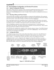
...configuration procedures. Prior to powering up the unit, the wiring harness must be corrected before proceeding. Any faults or discrepancies must be installed after completion of the harness checkout. The GTR 200 can be checked for proper connections to the aircraft systems and... knobs, buttons, and softkeys used to configure the unit settings for configuring the GTR 200 to the specific installation. Any faults or discrepancies should be connected to the wiring harness and antenna. 3.6.3 Configuration Mode The configuration pages shown in Section 3.4.2. Release the...
...configuration procedures. Prior to powering up the unit, the wiring harness must be corrected before proceeding. Any faults or discrepancies must be installed after completion of the harness checkout. The GTR 200 can be checked for proper connections to the aircraft systems and... knobs, buttons, and softkeys used to configure the unit settings for configuring the GTR 200 to the specific installation. Any faults or discrepancies should be connected to the wiring harness and antenna. 3.6.3 Configuration Mode The configuration pages shown in Section 3.4.2. Release the...

GTR 200 Installation Manual
Page 57
Figure A-4 Method A.2 (Daisy Chain) for Method A.1 are followed except that all "bunch up" in the harness and to use Method A. NOTE The original purpose for separating the shield drain termination (item 3) from the float termination (item 5) in Figure A-5. A GTR 200 Installation Manual Page A-7 Method A.2 (Daisy Chain) In rare situations where more braids need to...
Figure A-4 Method A.2 (Daisy Chain) for Method A.1 are followed except that all "bunch up" in the harness and to use Method A. NOTE The original purpose for separating the shield drain termination (item 3) from the float termination (item 5) in Figure A-5. A GTR 200 Installation Manual Page A-7 Method A.2 (Daisy Chain) In rare situations where more braids need to...