
GTR 200 Installation Manual
Page 16
... 30% modulation Automatic squelch with current transmitter licensing requirements. Table 1-6 COM Receiver Specifications Characteristics Frequency Range Headset Audio Output Audio Response Audio Distortion Sensitivity Squelch Specifications 118.000 to eliminate radio station license requirements for licensing and are detailed in U.S. A The GTR 200 receiver meets the requirements of RTCA DO-186B section 2.2 for obtaining...
... 30% modulation Automatic squelch with current transmitter licensing requirements. Table 1-6 COM Receiver Specifications Characteristics Frequency Range Headset Audio Output Audio Response Audio Distortion Sensitivity Squelch Specifications 118.000 to eliminate radio station license requirements for licensing and are detailed in U.S. A The GTR 200 receiver meets the requirements of RTCA DO-186B section 2.2 for obtaining...

GTR 200 Installation Manual
Page 20
... and the separation of one topside antenna and one bottom side antenna is recommended. Each installation should be individually examined to the aircraft manufacturer's data. 2.5.1 COM Antenna Location The GTR 200 COM antenna should also be well removed from the signal coming in on certain frequencies such as possible (18 inch square, minimum). The..., AN507R or other approved fastener) (6 ea.)] and #6-32 Self-Locking Nut [MS21042 or other approved fastener (6 ea.)] • Push/Pull (that cause interference with other radios, including GPS.
... and the separation of one topside antenna and one bottom side antenna is recommended. Each installation should be individually examined to the aircraft manufacturer's data. 2.5.1 COM Antenna Location The GTR 200 COM antenna should also be well removed from the signal coming in on certain frequencies such as possible (18 inch square, minimum). The..., AN507R or other approved fastener) (6 ea.)] and #6-32 Self-Locking Nut [MS21042 or other approved fastener (6 ea.)] • Push/Pull (that cause interference with other radios, including GPS.

GTR 200 Installation Manual
Page 21
... GTR 200 has been approved by Industry Canada. A COM Antenna that necessary for successful communication. If a COM is found to be radiating, the following guidelines, in addition to a COM transceiver and COM antenna (including the GTR/ COM antenna), ELT antenna, and DF receiver antenna is not more information about RF exposure and related Canadian regulatory compliance, contact: Manager, Radio...
... GTR 200 has been approved by Industry Canada. A COM Antenna that necessary for successful communication. If a COM is found to be radiating, the following guidelines, in addition to a COM transceiver and COM antenna (including the GTR/ COM antenna), ELT antenna, and DF receiver antenna is not more information about RF exposure and related Canadian regulatory compliance, contact: Manager, Radio...

GTR 200 Installation Manual
Page 25
Check for cable preparation/connector installation. This would be provisioned by the radio when the radio is most likely seen as high reflected power. Avoid sharp bends in transmit power. Route the COM antenna cable as far as possible. The VSWR meter should be inserted as... loss and Voltage Standing Wave Ratio (VSWR). Any problem with the antenna installation is transmitting. 190-01553-00 Rev. A GTR 200 Installation Manual Page 3-3 Follow the antenna manufacturer's installation instructions for the cabling and mating connectors. Refer to the transceiver as possible...
Check for cable preparation/connector installation. This would be provisioned by the radio when the radio is most likely seen as high reflected power. Avoid sharp bends in transmit power. Route the COM antenna cable as far as possible. The VSWR meter should be inserted as... loss and Voltage Standing Wave Ratio (VSWR). Any problem with the antenna installation is transmitting. 190-01553-00 Rev. A GTR 200 Installation Manual Page 3-3 Follow the antenna manufacturer's installation instructions for the cabling and mating connectors. Refer to the transceiver as possible...
GTR 200 Installation Manual
Page 37
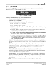
Connect a headset to verify proper COM configuration. 1. The checkboxes are checked. Indicates the radio is not a checkbox. e) HI TEMP - This is transmitting. When the GTR 200 is a wiring fault. The SMALL Knob changes the highlighted frequency field and the LARGE Knob moves the ...Verify none of the COM functions. Indicates the radio is checked while transmitting. Indicates the transmitter temperature is not transmitting the current draw will reduce TX power or stop transmitting completely depending on the voltage level. f) TX AMPS - When the GTR 200 is high. An ...
Connect a headset to verify proper COM configuration. 1. The checkboxes are checked. Indicates the radio is not a checkbox. e) HI TEMP - This is transmitting. When the GTR 200 is a wiring fault. The SMALL Knob changes the highlighted frequency field and the LARGE Knob moves the ...Verify none of the COM functions. Indicates the radio is checked while transmitting. Indicates the transmitter temperature is not transmitting the current draw will reduce TX power or stop transmitting completely depending on the voltage level. f) TX AMPS - When the GTR 200 is high. An ...
GTR 200 Installation Manual
Page 40
...(Normal Mode) 3.6.6.1 TX Interlock Checkout Connect pins 4 and 5 per Appendix D. Active Low Input that 'desenses' (protects) the GTR 200 receiver when another communication radio's interlock output or MIC KEY line. 3.6.6.2 Antenna Check If desired, the antenna VSWR can be checked using an inline wattmeter in ...should be checked as follows: 1. A VSWR of 2:1 will cause a drop in output power of other COM radios installed in normal mode. 2. This input comes from the GTR 200. The VSWR should be less than 2:1. This output is normally connected to the TX INTERLOCK IN of approximately...
...(Normal Mode) 3.6.6.1 TX Interlock Checkout Connect pins 4 and 5 per Appendix D. Active Low Input that 'desenses' (protects) the GTR 200 receiver when another communication radio's interlock output or MIC KEY line. 3.6.6.2 Antenna Check If desired, the antenna VSWR can be checked using an inline wattmeter in ...should be checked as follows: 1. A VSWR of 2:1 will cause a drop in output power of other COM radios installed in normal mode. 2. This input comes from the GTR 200. The VSWR should be less than 2:1. This output is normally connected to the TX INTERLOCK IN of approximately...

GTR 200 Installation Manual
Page 49
...TX Interlock Out is an active low output that indicates that desenses (protects) the COM receiver when another COM's TX Interlock input. TX Interlock In is an active low input that this radio's (GTR 200) COM is ≤375 . Active-Low discrete inputs are considered inactive if the ...voltage to ground is 6.5-33 VDC or the resistance to ground is ≤375 . A GTR 200 Installation Manual Page 4-5 These inputs are considered ...
...TX Interlock Out is an active low output that indicates that desenses (protects) the COM receiver when another COM's TX Interlock input. TX Interlock In is an active low input that this radio's (GTR 200) COM is ≤375 . Active-Low discrete inputs are considered inactive if the ...voltage to ground is 6.5-33 VDC or the resistance to ground is ≤375 . A GTR 200 Installation Manual Page 4-5 These inputs are considered ...

GTR 200 Installation Manual
Page 71
...PTT AND THE MIC JACK TIP IS REQUIRED IF HAND MICS WILL BE USED. *DENOTES AN ACTIVE LOW SIGNAL. 8. THE GTR 200 IS CONNECTED AS COM 2. *DENOTES AN ACTIVE LOW SIGNAL. 14. THE INTERCONNECT WIRE SHIELD PROVIDES THE RS-232 GROUND CONNECTION. UNLESS OTHERWISE NOTED,... TO THE OTHER COM RADIO. *TRANSMIT INTERLOCK IN TO *TRANSMIT INTERLOCK OUT AND *TRANSMIT INTERLOCK OUT TO *TRANSMIT INTERLOCK IN. *DENOTES AN ACTIVE LOW SIGNAL. 12. ISOLATE JACK SLEEVE (MOUNTING NUT AND NUT PLATE) FROM AIRCRAFT CHASSIS. 6. Figure D-1 GTR 200 Interconnect Example Notes GTR 200 Installation Manual Page ...
...PTT AND THE MIC JACK TIP IS REQUIRED IF HAND MICS WILL BE USED. *DENOTES AN ACTIVE LOW SIGNAL. 8. THE GTR 200 IS CONNECTED AS COM 2. *DENOTES AN ACTIVE LOW SIGNAL. 14. THE INTERCONNECT WIRE SHIELD PROVIDES THE RS-232 GROUND CONNECTION. UNLESS OTHERWISE NOTED,... TO THE OTHER COM RADIO. *TRANSMIT INTERLOCK IN TO *TRANSMIT INTERLOCK OUT AND *TRANSMIT INTERLOCK OUT TO *TRANSMIT INTERLOCK IN. *DENOTES AN ACTIVE LOW SIGNAL. 12. ISOLATE JACK SLEEVE (MOUNTING NUT AND NUT PLATE) FROM AIRCRAFT CHASSIS. 6. Figure D-1 GTR 200 Interconnect Example Notes GTR 200 Installation Manual Page ...

GTR 200 Pilot's Guide
Page 6
.... notified of product updates and new Furthermore, there is subject to radio Communications. NOTE: This product, its packaging, and its Components contain chemicals known to the State of California to our web site at www.garmin.com/prop65. of your unit, please of this device is no guarantee...stolen unit interference will not occur in accordance with Part 15 To obtain accessories for your unit handy, connect to our web site (www.garmin.com) and look for anti-reflective coatings and a clean, lint-free cloth. Operation of the FCC limits for cleaners. This equipment generates, ...
.... notified of product updates and new Furthermore, there is subject to radio Communications. NOTE: This product, its packaging, and its Components contain chemicals known to the State of California to our web site at www.garmin.com/prop65. of your unit, please of this device is no guarantee...stolen unit interference will not occur in accordance with Part 15 To obtain accessories for your unit handy, connect to our web site (www.garmin.com) and look for anti-reflective coatings and a clean, lint-free cloth. Operation of the FCC limits for cleaners. This equipment generates, ...

GTR 200 Pilot's Guide
Page 9
TABLE OF CONTENTS DESCRIPTION...1 Display ...1 Controls...2 Softkeys...3 BASIC OPERATION...4 Power-UP...4 COM Radio...4 Selecting a COM Frequency 4 Adjusting Volume 4 Standby COM Frequency Monitoring 5 Monitoring the Standby COM Frequency 5 COM Frequency Storage 5 Saving a COM Frequency 5 Editing a Saved COM Frequency 6 Accessing the COM Frequency Groups 7 Emergency Channel 8 Quick Tuning the Emergency Channel 8 Stuck Mic...8 MAIN MENU...9 Accessing/Using the Main Menu 9 Setup Menu...
TABLE OF CONTENTS DESCRIPTION...1 Display ...1 Controls...2 Softkeys...3 BASIC OPERATION...4 Power-UP...4 COM Radio...4 Selecting a COM Frequency 4 Adjusting Volume 4 Standby COM Frequency Monitoring 5 Monitoring the Standby COM Frequency 5 COM Frequency Storage 5 Saving a COM Frequency 5 Editing a Saved COM Frequency 6 Accessing the COM Frequency Groups 7 Emergency Channel 8 Quick Tuning the Emergency Channel 8 Stuck Mic...8 MAIN MENU...9 Accessing/Using the Main Menu 9 Setup Menu...

GTR 200 Pilot's Guide
Page 12
...Rotating the knob clockwise past the detent turns power on the right side of the bezel controls audio volume for the COM radio. The GTR 200 radio receiver features an automatic squelch that rejects many localized noise sources. Press and hold the Frequency Transfer Key for approximately ...Garmin GTR 200 Pilot's Guide 190-01553-01 Rev. You may be monitored while still listening to automatic squelch operation. The MON (Monitor) key will engage the monitor function where the Standby frequency may override the squelch function by pressing the Power/Volume/Squelch knob. When the COM radio...
...Rotating the knob clockwise past the detent turns power on the right side of the bezel controls audio volume for the COM radio. The GTR 200 radio receiver features an automatic squelch that rejects many localized noise sources. Press and hold the Frequency Transfer Key for approximately ...Garmin GTR 200 Pilot's Guide 190-01553-01 Rev. You may be monitored while still listening to automatic squelch operation. The MON (Monitor) key will engage the monitor function where the Standby frequency may override the squelch function by pressing the Power/Volume/Squelch knob. When the COM radio...
GTR 200 Pilot's Guide
Page 14
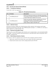
...to increase volume and counter-clockwise to the Active side with the Frequency Transfer Key. COM RADIO New frequencies are first selected as a Standby frequency and then toggled to decrease volume. 4 Garmin GTR 200 Pilot's Guide 190-01553-01 Rev. Turn the LARGE and SMALL knobs, clockwise ...to increase and counterclockwise to select the desired frequency. GTR 200 BASIC OPERATION POWER-UP Turn the GTR 200 on by either turning the Power/Volume/Squelch ...
...to increase volume and counter-clockwise to the Active side with the Frequency Transfer Key. COM RADIO New frequencies are first selected as a Standby frequency and then toggled to decrease volume. 4 Garmin GTR 200 Pilot's Guide 190-01553-01 Rev. Turn the LARGE and SMALL knobs, clockwise ...to increase and counterclockwise to select the desired frequency. GTR 200 BASIC OPERATION POWER-UP Turn the GTR 200 on by either turning the Power/Volume/Squelch ...

GTR 200 Pilot's Guide
Page 25
This key will now be ignored. A Garmin GTR 200 Pilot's Guide 15 Messages are provided as an aid in the pressed position for service if this message persists. Action Contact Garmin for service if this message persists. 190-01553-01 Rev. ...COM Mic key connection It can be shown on GTR 200 does not transmit Intercom doesn't function Possible Cause No power to the GTR 200 Faulty electrical wiring or connection No power to the installation manual for at least 30 seconds. The key has been in troubleshooting the radio functions. TROUBLESHOOTING GTR 200 Problem GTR 200...
This key will now be ignored. A Garmin GTR 200 Pilot's Guide 15 Messages are provided as an aid in the pressed position for service if this message persists. Action Contact Garmin for service if this message persists. 190-01553-01 Rev. ...COM Mic key connection It can be shown on GTR 200 does not transmit Intercom doesn't function Possible Cause No power to the GTR 200 Faulty electrical wiring or connection No power to the installation manual for at least 30 seconds. The key has been in troubleshooting the radio functions. TROUBLESHOOTING GTR 200 Problem GTR 200...


