
Installation Manual
Page 2
... Aviation Panel-Mount Technical Support Line (Toll Free) 1.888.606.5482 www.garmin.com Garmin (Europe) Ltd. A-6 B-1 - B-2 Page A Revision F GSR 56 Installation Manual 190-00836-00 iv 1-1 - 1-8 2-1 - 2-2 3-1 - 3-6 4-1 - 4-4 A-1 - Liberty House, Bulls Copse Road Hounsdown Business Park Southampton, SO40 9RB U.K. +44/ (0) 870.8501241 Garmin ...information C 01/04/10 Added info for new 011-02268-00 unit D 05/05/10 Added ETSO info for any revision hereto is strictly prohibited. or its subsidiaries All Rights Reserved Except as expressly provided herein, no part of this manual...
... Aviation Panel-Mount Technical Support Line (Toll Free) 1.888.606.5482 www.garmin.com Garmin (Europe) Ltd. A-6 B-1 - B-2 Page A Revision F GSR 56 Installation Manual 190-00836-00 iv 1-1 - 1-8 2-1 - 2-2 3-1 - 3-6 4-1 - 4-4 A-1 - Liberty House, Bulls Copse Road Hounsdown Business Park Southampton, SO40 9RB U.K. +44/ (0) 870.8501241 Garmin ...information C 01/04/10 Added info for new 011-02268-00 unit D 05/05/10 Added ETSO info for any revision hereto is strictly prohibited. or its subsidiaries All Rights Reserved Except as expressly provided herein, no part of this manual...
Installation Manual
Page 3
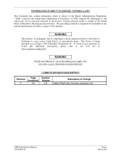
... is being provided in part of this manual. This Notice is required to be exported, released, or disclosed to foreign nationals inside or outside of the United States without first obtaining an export license. CURRENT REVISION DESCRIPTION Revision Page Number(s) F 3-5 Section Number 3.8 Description of Change Added Flight Data Services activation info GSR 56 Installation Manual 190-00836-00 Page i Revision F WARNING This product, its packaging...
... is being provided in part of this manual. This Notice is required to be exported, released, or disclosed to foreign nationals inside or outside of the United States without first obtaining an export license. CURRENT REVISION DESCRIPTION Revision Page Number(s) F 3-5 Section Number 3.8 Description of Change Added Flight Data Services activation info GSR 56 Installation Manual 190-00836-00 Page i Revision F WARNING This product, its packaging...
Installation Manual
Page 4
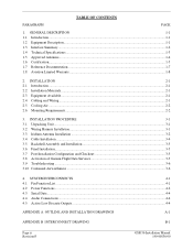
... Audio Connections...4-4 4.5 Active Low Discrete Outputs...4-4 APPENDIX A OUTLINE AND INSTALLATION DRAWINGS A-1 APPENDIX B INTERCONNECT DRAWING B-1 Page ii Revision F GSR 56 Installation Manual 190-00836-00 TABLE OF CONTENTS PARAGRAPH PAGE 1. INSTALLATION PROCEDURE 3-1 3.1 Unpacking Unit ...3-1 3.2 Wiring Harness Installation...3-1 3.3 Iridium Antenna Installation ...3-2 3.4 Cable Installation ...3-4 3.5 Backshell Assembly and Installation 3-5 3.6 Final Installation...3-5 3.7 Post Installation Configuration and Checkout 3-5 3.8 Activation of Garmin Flight Data Services...
... Audio Connections...4-4 4.5 Active Low Discrete Outputs...4-4 APPENDIX A OUTLINE AND INSTALLATION DRAWINGS A-1 APPENDIX B INTERCONNECT DRAWING B-1 Page ii Revision F GSR 56 Installation Manual 190-00836-00 TABLE OF CONTENTS PARAGRAPH PAGE 1. INSTALLATION PROCEDURE 3-1 3.1 Unpacking Unit ...3-1 3.2 Wiring Harness Installation...3-1 3.3 Iridium Antenna Installation ...3-2 3.4 Cable Installation ...3-4 3.5 Backshell Assembly and Installation 3-5 3.6 Final Installation...3-5 3.7 Post Installation Configuration and Checkout 3-5 3.8 Activation of Garmin Flight Data Services...

Installation Manual
Page 6
Authorized Garmin Sales and Service Centers are listed with the associated service bulletin number, service bulletin date, and the purpose of this manual (see date on the Garmin Dealer Resource web site at the time of publication of the modification. The following table identifies hardware modification (Mod) Levels for the GSR 56. Mod Levels are encouraged to access the most up-to change without...
Authorized Garmin Sales and Service Centers are listed with the associated service bulletin number, service bulletin date, and the purpose of this manual (see date on the Garmin Dealer Resource web site at the time of publication of the modification. The following table identifies hardware modification (Mod) Levels for the GSR 56. Mod Levels are encouraged to access the most up-to change without...
Installation Manual
Page 7
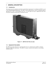
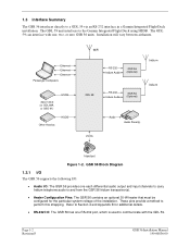
... specific installation instructions in rack) 1.2 Equipment Description The GSR 56 provides airborne low speed data link and voice communication capability to Garmin Integrated Flight Deck installations. Figure 1-1. The GSR 56 contains a transceiver that operates on the Iridium Satellite network. GSR 56 Installation Manual 190-00836-00 Page 1-1 Revision F The GSR 56 can be integrated into a variety of the Garmin Integrated Flight Deck. GSR 56 Unit View (in a particular aircraft. Use only approved (type or supplemental type) data for installing the GSR 56 as part...
... specific installation instructions in rack) 1.2 Equipment Description The GSR 56 provides airborne low speed data link and voice communication capability to Garmin Integrated Flight Deck installations. Figure 1-1. The GSR 56 contains a transceiver that operates on the Iridium Satellite network. GSR 56 Installation Manual 190-00836-00 Page 1-1 Revision F The GSR 56 can be integrated into a variety of the Garmin Integrated Flight Deck. GSR 56 Unit View (in a particular aircraft. Use only approved (type or supplemental type) data for installing the GSR 56 as part...
Installation Manual
Page 8
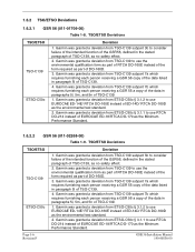
... Audio GSR 56 (Optional) Iridiu m Iridiu m POTS Audio Audio Panel(s) Hand set Figure 1-2. Page 1-2 Revision F GSR 56 Installation Manual 190-00836-00 Installation will vary between airframes. GSR 56 Block Diagram 1.3.1 I/O The GSR 56 supports the following I/O: • Audio I /O: The GSR 56 has one RS-232 port, which is used to communicate with one each differential audio output and input channels to carry Iridium telephone audio to a GDL 59 via an RS-232 interface in a Garmin Integrated Flight Deck installation. The GDL...
... Audio GSR 56 (Optional) Iridiu m Iridiu m POTS Audio Audio Panel(s) Hand set Figure 1-2. Page 1-2 Revision F GSR 56 Installation Manual 190-00836-00 Installation will vary between airframes. GSR 56 Block Diagram 1.3.1 I/O The GSR 56 supports the following I/O: • Audio I /O: The GSR 56 has one RS-232 port, which is used to communicate with one each differential audio output and input channels to carry Iridium telephone audio to a GDL 59 via an RS-232 interface in a Garmin Integrated Flight Deck installation. The GDL...

Installation Manual
Page 9
... of the installing agency to obtain the latest revision of the Garmin web site (www.garmin.com). 1.4.1 Physical Characteristics (Unit with Remote Rack) Table 1-1. Input Voltage Characteristic Specification Input Voltage 14/28 Vdc - See the Environmental Qualification Form for details on surge ratings and minimum/maximum operating voltages. Table 1-3. 1.4 Technical Specifications It is available directly from Garmin under the following part number: GSR 56 (011-01706...
... of the installing agency to obtain the latest revision of the Garmin web site (www.garmin.com). 1.4.1 Physical Characteristics (Unit with Remote Rack) Table 1-1. Input Voltage Characteristic Specification Input Voltage 14/28 Vdc - See the Environmental Qualification Form for details on surge ratings and minimum/maximum operating voltages. Table 1-3. 1.4 Technical Specifications It is available directly from Garmin under the following part number: GSR 56 (011-01706...

Installation Manual
Page 10
Iridium Antenna Minimum Requirements Characteristics Frequency Range Gain (Typical) Polarization Nominal Output Impedance Operating Temperature Gain Antenna Cable Loss (transmit and receive) *STC/Installation dependent Specifications 1616 to 1626.5 MHz 3dBnc Right Hand Circular Polarization (RHCP) 50 ohms -50 to +60°C. Antcom S3IR16RR 4. For more details see Environmental Qualification Form. ...
Iridium Antenna Minimum Requirements Characteristics Frequency Range Gain (Typical) Polarization Nominal Output Impedance Operating Temperature Gain Antenna Cable Loss (transmit and receive) *STC/Installation dependent Specifications 1616 to 1626.5 MHz 3dBnc Right Hand Circular Polarization (RHCP) 50 ohms -50 to +60°C. Antcom S3IR16RR 4. For more details see Environmental Qualification Form. ...

Installation Manual
Page 11
... cockpit and cabin for Non Required Telecommunication Services (In Non Aeronautical Frequency Bands) TSO TSO-C139 ETSO-C50c ETSO-2C514 Category Class 2/Category 1 GSR 56 Installation Manual 190-00836-00 Page 1-5 Revision F The Appliance Project Identifier (API) for the TSO approval of this article either on or within the TSO standards. see applicable hardware and software part numbers to determine that the aircraft installation conditions are within a specific...
... cockpit and cabin for Non Required Telecommunication Services (In Non Aeronautical Frequency Bands) TSO TSO-C139 ETSO-C50c ETSO-2C514 Category Class 2/Category 1 GSR 56 Installation Manual 190-00836-00 Page 1-5 Revision F The Appliance Project Identifier (API) for the TSO approval of this article either on or within the TSO standards. see applicable hardware and software part numbers to determine that the aircraft installation conditions are within a specific...
Installation Manual
Page 12
... 1. TSO/ETSO Deviations TSO/ETSO TSO-C139 ETSO-C50c Deviation 1. Garmin was granted a deviation from TSO-C139 subpart 7b which requires furnishing each person receiving a GSR 56 copy of the data listed in paragraphs 5l, 5m, and 5n of TSO-C139. 4. Page 1-6 Revision F GSR 56 Installation Manual 190-00836-00 Garmin was granted a deviation from ETSO-C50c § 3.1.2 to use the environmental qualification form as part of...
... 1. TSO/ETSO Deviations TSO/ETSO TSO-C139 ETSO-C50c Deviation 1. Garmin was granted a deviation from TSO-C139 subpart 7b which requires furnishing each person receiving a GSR 56 copy of the data listed in paragraphs 5l, 5m, and 5n of TSO-C139. 4. Page 1-6 Revision F GSR 56 Installation Manual 190-00836-00 Garmin was granted a deviation from ETSO-C50c § 3.1.2 to use the environmental qualification form as part of...

Installation Manual
Page 13
Referenced Publications Part Number 005-00432-10 005-00554-10 190-00303-00 190-00303-04 Document GSR 56 (011-01706-00) Environmental Qualification Form GSR 56 (011-02268-00) Environmental Qualification Form G1000 System Installation Manual G1000 Line Maintenance and Configuration Manual GSR 56 Installation Manual 190-00836-00 Page 1-7 Revision F Table 1-11. Non-TSO Functions Function Iridium satellite radio transceiver Design Assurance RTCA/DO-178B Level E 1.7 Reference Documentation...
Referenced Publications Part Number 005-00432-10 005-00554-10 190-00303-00 190-00303-04 Document GSR 56 (011-01706-00) Environmental Qualification Form GSR 56 (011-02268-00) Environmental Qualification Form G1000 System Installation Manual G1000 Line Maintenance and Configuration Manual GSR 56 Installation Manual 190-00836-00 Page 1-7 Revision F Table 1-11. Non-TSO Functions Function Iridium satellite radio transceiver Design Assurance RTCA/DO-178B Level E 1.7 Reference Documentation...
Installation Manual
Page 14
...and/or used in the United States or Canada must be made at its sole option, repair or replace any country. If applicable, this distributor provides local service for devices purchased outside the United States depending on the country. THIS WARRANTY GIVES YOU SPECIFIC LEGAL RIGHTS,... YOU. Distributor warranties are not eligible for new portable products and any transportation cost. Phone: 44/ (0) 870.8501241 FAX: 44/ (0) 870.850125 Page 1-8 Revision F GSR 56 Installation Manual 190-00836-00 THE WARRANTIES AND REMEDIES CONTAINED HEREIN ARE EXCLUSIVE AND IN LIEU OF...
...and/or used in the United States or Canada must be made at its sole option, repair or replace any country. If applicable, this distributor provides local service for devices purchased outside the United States depending on the country. THIS WARRANTY GIVES YOU SPECIFIC LEGAL RIGHTS,... YOU. Distributor warranties are not eligible for new portable products and any transportation cost. Phone: 44/ (0) 870.8501241 FAX: 44/ (0) 870.850125 Page 1-8 Revision F GSR 56 Installation Manual 190-00836-00 THE WARRANTIES AND REMEDIES CONTAINED HEREIN ARE EXCLUSIVE AND IN LIEU OF...
Installation Manual
Page 15
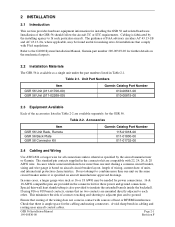
... of the GSR 56 should follow the aircraft TC or STC requirements. 2 INSTALLATION 2.1 Introduction This section provides hardware equipment information for making retro-fit installations that there is specified on aircraft manufacturer approved drawings. Accessories Item GSR 56 Unit Rack, Remote GSR 56 Back Plate GSR 56 Connector Kit Garmin Catalog Part Number 115-01018-00 011-01800-00 011-01732-00 2.4 Cabling and Wiring Use AWG #24 or larger wire for all connections unless otherwise...
... of the GSR 56 should follow the aircraft TC or STC requirements. 2 INSTALLATION 2.1 Introduction This section provides hardware equipment information for making retro-fit installations that there is specified on aircraft manufacturer approved drawings. Accessories Item GSR 56 Unit Rack, Remote GSR 56 Back Plate GSR 56 Connector Kit Garmin Catalog Part Number 115-01018-00 011-01800-00 011-01732-00 2.4 Cabling and Wiring Use AWG #24 or larger wire for all connections unless otherwise...
Installation Manual
Page 16
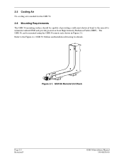
Figure 2-1. Refer to minimize radiated EMI and provide protection from High-Intensity Radiation Fields (HIRF). GSR 56 Remote Unit Rack Page 2-2 Revision F GSR 56 Installation Manual 190-00836-00 2.5 Cooling Air No cooling air is needed for details. The GSR 56 can be capable of providing a sufficient electrical bond to the aircraft to the Figure A-1 GSR 56 Outline and Installation Drawing for the GSR 56. 2.6 Mounting Requirements The GSR 56 mounting surface should be mounted using the GSR 56 remote rack shown in Figure 2-1.
Figure 2-1. Refer to minimize radiated EMI and provide protection from High-Intensity Radiation Fields (HIRF). GSR 56 Remote Unit Rack Page 2-2 Revision F GSR 56 Installation Manual 190-00836-00 2.5 Cooling Air No cooling air is needed for details. The GSR 56 can be capable of providing a sufficient electrical bond to the aircraft to the Figure A-1 GSR 56 Outline and Installation Drawing for the GSR 56. 2.6 Mounting Requirements The GSR 56 mounting surface should be mounted using the GSR 56 remote rack shown in Figure 2-1.

Installation Manual
Page 17
... GSR 56 Installation Manual 190-00836-00 Page 3-1 Revision F To justify a claim, save the original shipping container and all input and output signals. See Appendix B for evidence of damage incurred during shipment. 3 INSTALLATION PROCEDURE 3.1 Unpacking Unit Carefully unpack the equipment and make a visual inspection of the unit for examples of interconnect wiring diagrams. Construct the actual harnesses in accordance with the connector kit (Refer to Garmin...
... GSR 56 Installation Manual 190-00836-00 Page 3-1 Revision F To justify a claim, save the original shipping container and all input and output signals. See Appendix B for evidence of damage incurred during shipment. 3 INSTALLATION PROCEDURE 3.1 Unpacking Unit Carefully unpack the equipment and make a visual inspection of the unit for examples of interconnect wiring diagrams. Construct the actual harnesses in accordance with the connector kit (Refer to Garmin...
Installation Manual
Page 18
... to take into consideration before installing an antenna for information regarding connector crimp positioner tooling. 3.3 Iridium Antenna Installation For use with the GSR 56, Iridium antennas have good conductivity between the antenna and the skin of the Iridium antenna, follow the manufacturer's instructions and the instructions in the following sections. 3.3.1 Antenna Mounting For installation mounting of the aircraft should be used when reassembling the connector. 3. For applications using an extractor due to...
... to take into consideration before installing an antenna for information regarding connector crimp positioner tooling. 3.3 Iridium Antenna Installation For use with the GSR 56, Iridium antennas have good conductivity between the antenna and the skin of the Iridium antenna, follow the manufacturer's instructions and the instructions in the following sections. 3.3.1 Antenna Mounting For installation mounting of the aircraft should be used when reassembling the connector. 3. For applications using an extractor due to...

Installation Manual
Page 19
... multiple Iridium GSR 56 installations. 4. 3.3.3 Iridium Antenna Location As with an unobstructed view of the sky above the aircraft when in level flight. The Iridium antenna must be observed when selecting an antenna location are as the vertical stabilizer will limit the reception of the satellite signal. 2. The minimum distances to each other control surface actuators and motors. Locating antennas too close proximity to be mounted on...
... multiple Iridium GSR 56 installations. 4. 3.3.3 Iridium Antenna Location As with an unobstructed view of the sky above the aircraft when in level flight. The Iridium antenna must be observed when selecting an antenna location are as the vertical stabilizer will limit the reception of the satellite signal. 2. The minimum distances to each other control surface actuators and motors. Locating antennas too close proximity to be mounted on...

Installation Manual
Page 20
... connector installation. TNC Connector Installation Page 3-4 Revision F GSR 56 Installation Manual 190-00836-00 The maximum cable loss between the GSR 56 and the satellite antenna (transmit or receive) is critical to the performance of the GSR 56 to keep the cable loss of the coaxial run can be less than 1.4:1 when the cable is terminated in Figure 3-2. For routing convenience, one end of the antenna cable to the desired length and install TNC connectors...
... connector installation. TNC Connector Installation Page 3-4 Revision F GSR 56 Installation Manual 190-00836-00 The maximum cable loss between the GSR 56 and the satellite antenna (transmit or receive) is critical to the performance of the GSR 56 to keep the cable loss of the coaxial run can be less than 1.4:1 when the cable is terminated in Figure 3-2. For routing convenience, one end of the antenna cable to the desired length and install TNC connectors...
Installation Manual
Page 21
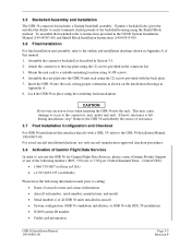
... rack. Remove the GSR 56 and identify the source of this manual. 1. Garmin's backshell also gives the installer the ability to easily terminate shield grounds at one of Garmin Flight Data Services In order to the outline and installation drawings shown in Appendix A. 6. Mount the unit rack to calling: • Name of aircraft owner and contact information • Aircraft tail number, serial number, manufacturer, and model • Serial number(s) of all GSR 56 units installed in Section...
... rack. Remove the GSR 56 and identify the source of this manual. 1. Garmin's backshell also gives the installer the ability to easily terminate shield grounds at one of Garmin Flight Data Services In order to the outline and installation drawings shown in Appendix A. 6. Mount the unit rack to calling: • Name of aircraft owner and contact information • Aircraft tail number, serial number, manufacturer, and model • Serial number(s) of all GSR 56 units installed in Section...

Installation Manual
Page 22
... aircraft maintenance requirements. Troubleshooting Problem Action • Check power wiring and pin out. No or low-quality signal • Ensure the Iridium antenna has an unobstructed view of the GSR 56 is adequate. No audio output • Check wiring from GSR 56 to make a phone call • Verify signal quality is adequate • Verify communication between GSR 56 and the display/control device 3.10 Continued Airworthiness Maintenance of satellite constellation. • Check the antenna cable and connectors. • Verify antenna...
... aircraft maintenance requirements. Troubleshooting Problem Action • Check power wiring and pin out. No or low-quality signal • Ensure the Iridium antenna has an unobstructed view of the GSR 56 is adequate. No audio output • Check wiring from GSR 56 to make a phone call • Verify signal quality is adequate • Verify communication between GSR 56 and the display/control device 3.10 Continued Airworthiness Maintenance of satellite constellation. • Check the antenna cable and connectors. • Verify antenna...


